2008 INFINITI FX35 air condition
[x] Cancel search: air conditionPage 2887 of 3924
SERVICE INFORMATION FOR ELECTRICAL INCIDENTGI-25
< SERVICE INFORMATION >
C
DE
F
G H
I
J
K L
M B
GI
N
O P
How to Perform Efficient Diagnos is for an Electrical IncidentINFOID:0000000001325672
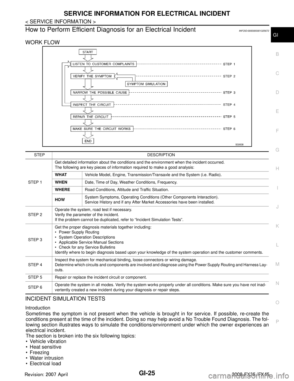
WORK FLOW
INCIDENT SIMULATION TESTS
Introduction
Sometimes the symptom is not present when the vehicle is brought in for service. If possible, re-create the
conditions present at the time of the incident. Doi ng so may help avoid a No Trouble Found Diagnosis. The fol-
lowing section illustrates ways to simulate the c onditions/environment under which the owner experiences an
electrical incident.
The section is broken into the six following topics:
Vehicle vibration
Heat sensitive
Freezing
Water intrusion
Electrical load
SGI838
STEP DESCRIPTION
STEP 1 Get detailed information about the conditions and the environment when the incident occurred.
The following are key pieces of information required to make a good analysis:
WHAT
Vehicle Model, Engine, Transmission/Transaxle and the System (i.e. Radio).
WHEN Date, Time of Day, Weather Conditions, Frequency.
WHERE Road Conditions, Altitude and Traffic Situation.
HOW System Symptoms, Operating Conditions (Other Components Interaction).
Service History and if any After Market Accessories have been installed.
STEP 2 Operate the system, road test if necessary.
Verify the parameter of the incident.
If the problem cannot be duplicated, refer to “Incident Simulation Tests”.
STEP 3 Get the proper diagnosis materials together including:
Power Supply Routing
System Operation Descriptions
Applicable Service Manual Sections
Check for any Service Bulletins
Identify where to begin diagnosis based upon your knowledge of the system operation and the customer comments.
STEP 4 Inspect the system for mechanical binding, loose connectors or wiring damage.
Determine which circuits and components are involved and diagnose using the Power Supply Routing and Harness Lay-
outs.
STEP 5 Repair or replace the incident circuit or component.
STEP 6 Operate the system in all modes. Verify the system works properly under all conditions. Make sure you have not inad-
vertently created a new incident during your diagnosis or repair steps.
3AA93ABC3ACD3AC03ACA3AC03AC63AC53A913A773A893A873A873A8E3A773A983AC73AC93AC03AC3
3A893A873A873A8F3A773A9D3AAF3A8A3A8C3A863A9D3AAF3A8B3A8C
Page 2889 of 3924
SERVICE INFORMATION FOR ELECTRICAL INCIDENTGI-27
< SERVICE INFORMATION >
C
DE
F
G H
I
J
K L
M B
GI
N
O P
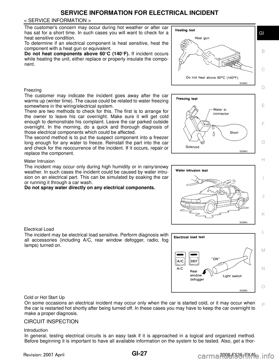
The customer's concern may occur during hot weather or after car
has sat for a short time. In such cases you will want to check for a
heat sensitive condition.
To determine if an electrical com ponent is heat sensitive, heat the
component with a heat gun or equivalent.
Do not heat components above 60 °C (140 °F). If incident occurs
while heating the unit, either replac e or properly insulate the compo-
nent.
Freezing
The customer may indicate the incident goes away after the car
warms up (winter time). The cause could be related to water freezing
somewhere in the wiring/electrical system.
There are two methods to check for this. The first is to arrange for
the owner to leave his car overnight. Make sure it will get cold
enough to demonstrate his complaint. Leave the car parked outside
overnight. In the morning, do a quick and thorough diagnosis of
those electrical components which could be affected.
The second method is to put the suspect component into a freezer
long enough for any water to freeze. Reinstall the part into the car
and check for the reoccurrence of the incident. If it occurs, repair or
replace the component.
Water Intrusion
The incident may occur only during high humidity or in rainy/snowy
weather. In such cases the incident could be caused by water intru-
sion on an electrical part. This c an be simulated by soaking the car
or running it through a car wash.
Do not spray water directly on any electrical components.
Electrical Load
The incident may be electrical load sensitive. Perform diagnosis with
all accessories (including A/C, rear window defogger, radio, fog
lamps) turned on.
Cold or Hot Start Up
On some occasions an electrical incident may occur only when the car is started cold, or it may occur when
the car is restarted hot shortly after being turned off. In these cases you may have to keep the car overnight to
make a proper diagnosis.
CIRCUIT INSPECTION
Introduction
In general, testing electrical circuits is an easy ta sk if it is approached in a logical and organized method.
Before beginning it is important to have all available in formation on the system to be tested. Also, get a thor-
SGI842
SGI843
SGI844
SGI845
3AA93ABC3ACD3AC03ACA3AC03AC63AC53A913A773A893A873A873A8E3A773A983AC73AC93AC03AC3
3A893A873A873A8F3A773A9D3AAF3A8A3A8C3A863A9D3AAF3A8B3A8C
Page 2896 of 3924
GI-34
< SERVICE INFORMATION >
CONSULT-III/GST CHECKING SYSTEM
CONSULT-III/GST CHECKING SYSTEM
DescriptionINFOID:0000000001572193
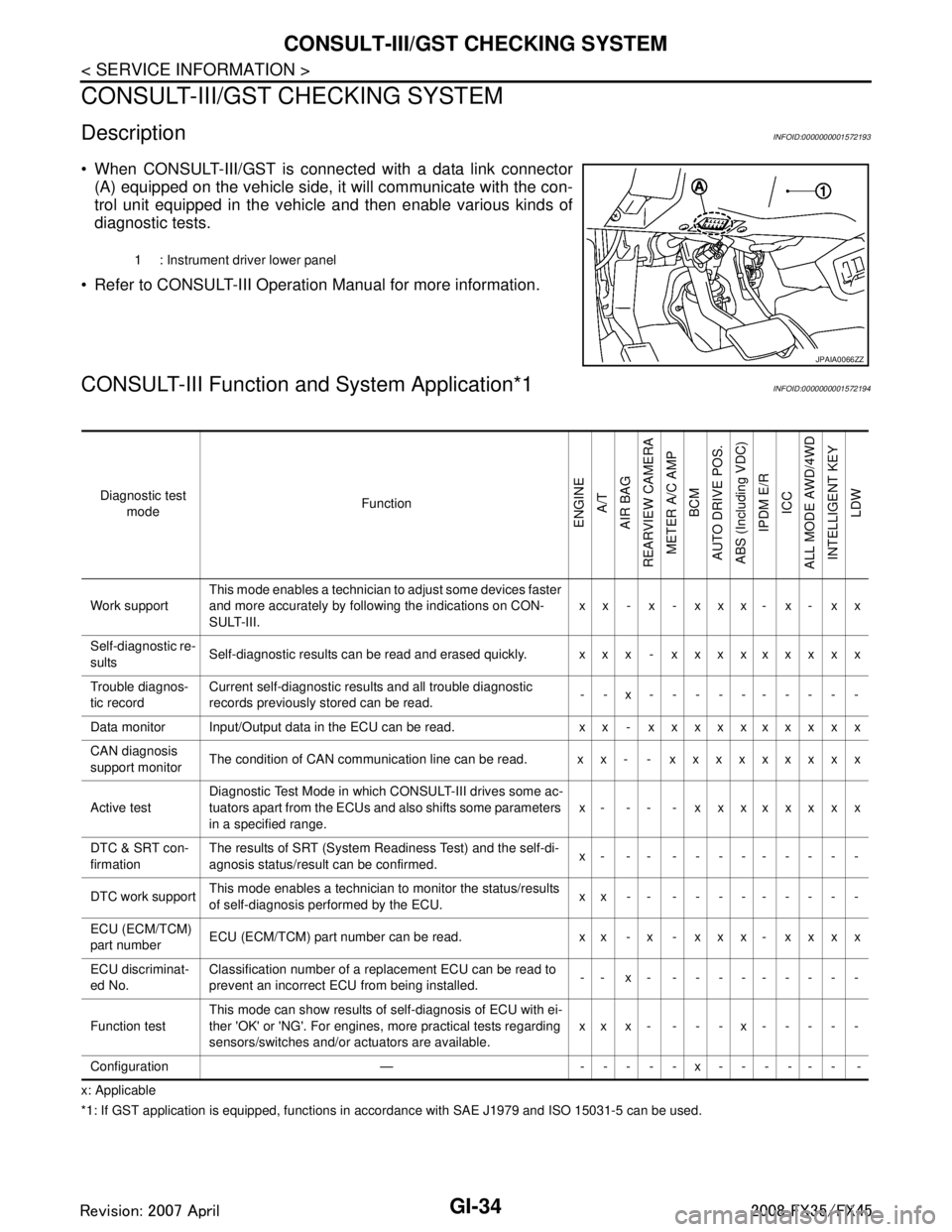
When CONSULT-III/GST is connected with a data link connector
(A) equipped on the vehicle side, it will communicate with the con-
trol unit equipped in the vehicle and then enable various kinds of
diagnostic tests.
Refer to CONSULT-III Operation Manual for more information.
CONSULT-III Function a nd System Application*1INFOID:0000000001572194
x: Applicable
*1: If GST application is eq uipped, functions in accordance with SAE J1979 and ISO 15031-5 can be used.
1 : Instrument driver lower panel
JPAIA0066ZZ
Diagnostic test
mode Function
ENGINE
A/T
AIR BAG
REARVIEW CAMERA
METER A/C AMP BCM
AUTO DRIVE POS.
ABS (Including VDC) IPDM E/R
ICC
ALL MODE AWD/4WD INTELLIGENT KEY LDW
Work support This mode enables a technician to adjust some devices faster
and more accurately by following the indications on CON-
SULT-III. xx - x - xxx- x- xx
Self-diagnostic re-
sults Self-diagnostic results can be read and erased quickly. xxx - xxxxxxxxx
Trouble diagnos-
tic record Current self-diagnostic results and all trouble diagnostic
records previously stored can be read.
--x----------
Data monitor Input/Output data in the ECU can be read. xx - xxxxxxxxxx
CAN diagnosis
support monitor The condition of CAN communication line can be read. xx- - xxxxxxxxx
Active test Diagnostic Test Mode in whic
h CONSULT-III drives some ac-
tuators apart from the ECUs and also shifts some parameters
in a specified range. x- -- - xxxxxxxx
DTC & SRT con-
firmation The results of SRT (System Readiness Test) and the self-di-
agnosis status/result can be confirmed.
x- -- ---------
DTC work support This mode enables a technician to monitor the status/results
of self-diagnosis performed by the ECU. xx-- ---------
ECU (ECM/TCM)
part number ECU (ECM/TCM) part number can be read. x x - x - x x x - x x x x
ECU discriminat-
ed No. Classification number of a replacement ECU can be read to
prevent an incorrect ECU from being installed.
-- x- ---------
Function test This mode can show results of self-diagnosis of ECU with ei-
ther 'OK' or 'NG'. For engines, more practical tests regarding
sensors/switches and/or actuators are available.
xxx- ---x-----
Configuration — -----x------ -
3AA93ABC3ACD3AC03ACA3AC03AC63AC53A913A773A893A873A873A8E3A773A983AC73AC93AC03AC3
3A893A873A873A8F3A773A9D3AAF3A8A3A8C3A863A9D3AAF3A8B3A8C
Page 2918 of 3924
SQUEAK AND RATTLE TROUBLE DIAGNOSESGW-5
< SERVICE INFORMATION >
C
DE
F
G H
J
K L
M A
B
GW
N
O P
SQUEAK AND RATTLE TROUBLE DIAGNOSES
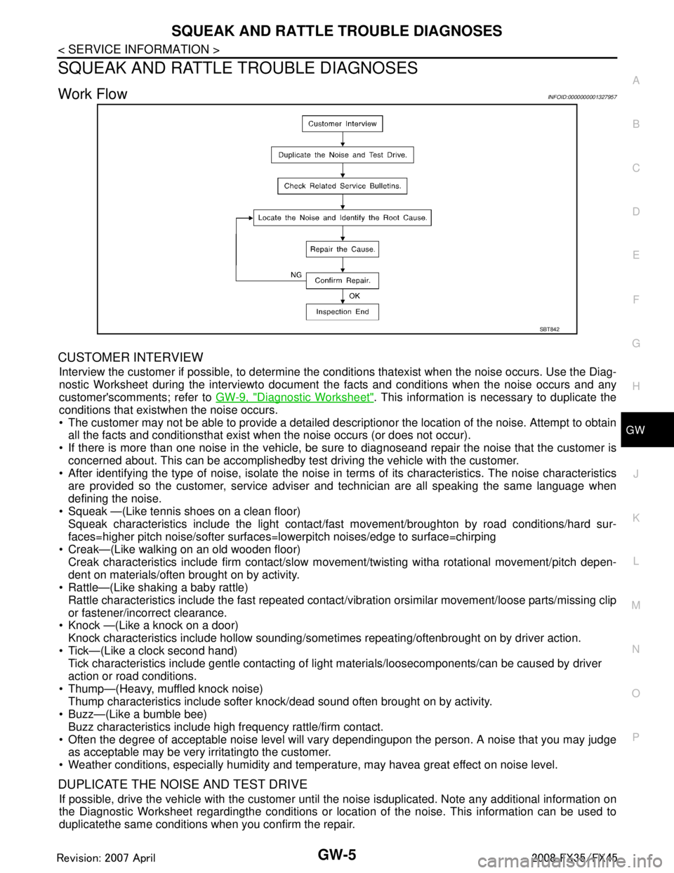
Work FlowINFOID:0000000001327957
CUSTOMER INTERVIEW
Interview the customer if possible, to determine the conditions thatexist when the noise occurs. Use the Diag-
nostic Worksheet during the interviewto document t he facts and conditions when the noise occurs and any
customer'scomments; refer to GW-9, "
Diagnostic Worksheet". This information is necessary to duplicate the
conditions that existwhen the noise occurs.
The customer may not be able to provide a detailed descriptionor the location of the noise. Attempt to obtain all the facts and conditionsthat exist w hen the noise occurs (or does not occur).
If there is more than one noise in the vehicle, be sure to diagnoseand repair the noise that the customer is
concerned about. This can be accomplishedby test driving the vehicle with the customer.
After identifying the type of noise, isolate the noise in terms of its characteristics. The noise characteristics
are provided so the customer, service adviser and technician are all speaking the same language when
defining the noise.
Squeak —(Like tennis shoes on a clean floor)
Squeak characteristics include the light contact/fa st movement/broughton by road conditions/hard sur-
faces=higher pitch noise/softer surfaces=l owerpitch noises/edge to surface=chirping
Creak—(Like walking on an old wooden floor)
Creak characteristics include firm contact/slow mo vement/twisting witha rotational movement/pitch depen-
dent on materials/often brought on by activity.
Rattle—(Like shaking a baby rattle)
Rattle characteristics include the fast repeated contac t/vibration orsimilar movement/loose parts/missing clip
or fastener/incorrect clearance.
Knock —(Like a knock on a door)
Knock characteristics include hollow sounding/some times repeating/oftenbrought on by driver action.
Tick—(Like a clock second hand) Tick characteristics include gentle contacting of li ght materials/loosecomponents/can be caused by driver
action or road conditions.
Thump—(Heavy, muffled knock noise) Thump characteristics include softer k nock/dead sound often brought on by activity.
Buzz—(Like a bumble bee)
Buzz characteristics include high frequency rattle/firm contact.
Often the degree of acceptable noise level will vary dependingupon the person. A noise that you may judge as acceptable may be very irritatingto the customer.
Weather conditions, especially humidity and temper ature, may havea great effect on noise level.
DUPLICATE THE NOISE AND TEST DRIVE
If possible, drive the vehicle with the customer until the noise isduplicated. Note any additional information on
the Diagnostic Worksheet regardingthe conditions or location of the noise. This information can be used to
duplicatethe same conditions when you confirm the repair.
SBT842
3AA93ABC3ACD3AC03ACA3AC03AC63AC53A913A773A893A873A873A8E3A773A983AC73AC93AC03AC3
3A893A873A873A8F3A773A9D3AAF3A8A3A8C3A863A9D3AAF3A8B3A8C
Page 2920 of 3924
SQUEAK AND RATTLE TROUBLE DIAGNOSESGW-7
< SERVICE INFORMATION >
C
DE
F
G H
J
K L
M A
B
GW
N
O P
Insulates where slight movement is present. Ideal for instrument panel applications.
SILICONE GREASE
Used in place of UHMW tape that will be visible or not fit.
Note: Will only last a few months.
SILICONE SPRAY
Use when grease cannot be applied.
DUCT TAPE
Use to eliminate movement.
CONFIRM THE REPAIR
Confirm that the cause of a noise is repaired by test driving the vehicle.Operate the vehicle under the same
conditions as when the noise originallyoccurred. Refer to the notes on the Diagnostic Worksheet.
Generic Squeak and Rattle TroubleshootingINFOID:0000000001327958
Refer to Table of Contents for specific component removal and installationinformation.
INSTRUMENT PANEL
Most incidents are caused by contact and movement between:
1. The cluster lid A and instrument panel
2. Acrylic lens and combination meter housing
3. Instrument panel to front pillar garnish
4. Instrument panel to windshield
5. Instrument panel mounting pins
6. Wiring harnesses behind the combination meter
7. A/C defroster duct and duct joint
These incidents can usually be located by tapping or moving the components to duplicate the noise or by
pressing on the components while driving to stop the noi se. Most of these incidents can be repaired by apply-
ing felt cloth tape or silicon spray (in hard to reach areas). Urethane pads can be used to insulate wiring har-
ness.
CAUTION:
Do not use silicone spray to isolat e a squeak or rattle. If you saturatet he area with silicone, you will not
be able to recheck the repair.
CENTER CONSOLE
Components to pay attention to include:
1. Shifter assembly cover to finisher
2. A/C control unit and cluster lid C
3. Wiring harnesses behind audio and A/C control unit
The instrument panel repair and isolation procedures also apply to thecenter console.
DOORS
Pay attention to the:
1. Finisher and inner panel making a slapping noise
2. Inside handle escutcheon to door finisher
3. Wiring harnesses tapping
4. Door striker out of alignment causing a popping noise on startsand stops
Tapping or moving the components or pressing on them while driving to duplicate the conditions can isolate
many of these incidents. You can usually insulate the ar eas with felt cloth tape or insulator foam blocks from
the Nissan Squeak and Rattle Kit (J43980) to repair the noise.
TRUNK
Trunk noises are often caused by a loose jack or loose items put intothe trunk by the owner.
In addition look for:
1. Trunk lid dumpers out of adjustment
2. Trunk lid striker out of adjustment
3. The trunk lid torsion bars knocking together
4. A loose license plate or bracket
3AA93ABC3ACD3AC03ACA3AC03AC63AC53A913A773A893A873A873A8E3A773A983AC73AC93AC03AC3
3A893A873A873A8F3A773A9D3AAF3A8A3A8C3A863A9D3AAF3A8B3A8C
Page 2921 of 3924

GW-8
< SERVICE INFORMATION >
SQUEAK AND RATTLE TROUBLE DIAGNOSES
Most of these incidents can be repaired by adjusting, securing or insulatingthe item(s) or component(s) caus-
ing the noise.
SUNROOF/HEADLINING
Noises in the sunroof/headlining area c an often be traced to one of the following:
1. Sunroof lid, rail, linkage or seals making a rattle or light knockingnoise
2. Sunvisor shaft shaking in the holder
3. Front or rear windshield touching headlining and squeaking
Again, pressing on the components to stop the noise while duplicatingthe conditions can isolate most of these
incidents. Repairs usually consistof insulating with felt cloth tape.
SEATS
When isolating seat noise it's important to note the pos ition the seatis in and the load placed on the seat when
the noise is present. These conditionsshould be duplic ated when verifying and isolating the cause of the
noise.
Cause of seat noise include:
1. Headrest rods and holder
2. A squeak between the seat pad cushion and frame
3. The rear seatback lock and bracket
These noises can be isolated by moving or pressing on the suspectedcomponents while duplicating the condi-
tions under which the noise occurs.Most of these incidents can be repaired by repositioning the component
orapplying urethane tape to the contact area.
UNDERHOOD
Some interior noise may be caused by components under the hood or onthe engine wall. The noise is then
transmitted into the passenger compartment.
Causes of transmitted underhood noise include:
1. Any component mounted to the engine wall
2. Components that pass through the engine wall
3. Engine wall mounts and connectors
4. Loose radiator mounting pins
5. Hood bumpers out of adjustment
6. Hood striker out of adjustment
These noises can be difficult to isolate since they cannot be reached from the interior of the vehicle. The best
method is to secure, move or insulate one component at a time and test drive the \
vehicle. Also, engine RPM
or load can be changed to isolate the noise. Repairs can usually be made by moving, adjusting, securing, or
insulating the component causing the noise.
3AA93ABC3ACD3AC03ACA3AC03AC63AC53A913A773A893A873A873A8E3A773A983AC73AC93AC03AC3
3A893A873A873A8F3A773A9D3AAF3A8A3A8C3A863A9D3AAF3A8B3A8C
Page 2940 of 3924
POWER WINDOW SYSTEMGW-27
< SERVICE INFORMATION >
C
DE
F
G H
J
K L
M A
B
GW
N
O P
Work FlowINFOID:0000000001327972
1. Check the symptom and customer's requests.
2. Understand the outline of system. Refer to GW-15, "
System Description"
3. According to the trouble diagnosis chart, repa ir or replace the cause of the malfunction.
Refer to GW-27, "
Trouble Diagnosis Symptom Chart".
4. Does power window system operate normally ? Yes, GO TO 5, If No, GO TO 3.
5. INSPECTION END
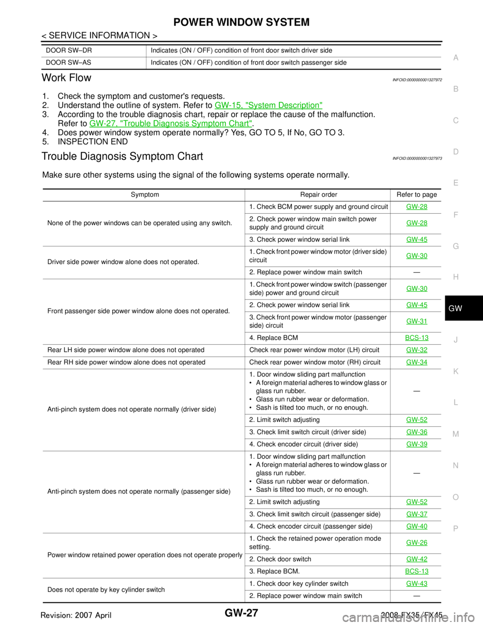
Trouble Diagnosis Symptom ChartINFOID:0000000001327973
Make sure other systems using the signal of the following systems operate normally.
DOOR SW–DR Indicates (ON / OFF) condition of front door switch driver side
DOOR SW–AS Indicates (ON / OFF) condition of front door switch passenger side
Symptom Repair order Refer to page
None of the power windows can be operated using any switch. 1. Check BCM power supply and ground circuit
GW-28
2. Check power window main switch power
supply and ground circuitGW-28
3. Check power window serial link
GW-45
Driver side power window alone does not operated. 1. Check front power wind
ow motor (driver side)
circuit GW-30
2. Replace power window main switch —
Front passenger side power window alone does not operated. 1. Check front power window switch (passenger
side) power and ground circuit
GW-30
2. Check power window serial link
GW-45
3. Check front power window motor (passenger
side) circuitGW-31
4. Replace BCM
BCS-13
Rear LH side power window alone does not operated Check rear power window motor (LH) circuit GW-32
Rear RH side power window alone does not operated Check rear power window motor (RH) circuitGW-34
Anti-pinch system does not operate normally (driver side)1. Door window sliding part malfunction
A foreign material adheres to window glass or
glass run rubber.
Glass run rubber wear or deformation.
Sash is tilted too much, or no enough. —
2. Limit switch adjusting GW-52
3. Check limit switch circuit (driver side)GW-36
4. Check encoder circuit (driver side) GW-39
Anti-pinch system does not operate normally (passenger side) 1. Door window sliding part malfunction
A foreign material adheres to window glass or
glass run rubber.
Glass run rubber wear or deformation.
Sash is tilted too much, or no enough. —
2. Limit switch adjusting GW-52
3. Check limit switch circuit (passenger side)GW-37
4. Check encoder circuit (passenger side)GW-40
Power window retained power operation does not operate properly 1. Check the retained power operation mode
setting.
GW-262. Check door switch
GW-42
3. Replace BCM.BCS-13
Does not operate by key cylinder switch 1. Check door key cylinder switch
GW-432. Replace power window main switch —
3AA93ABC3ACD3AC03ACA3AC03AC63AC53A913A773A893A873A873A8E3A773A983AC73AC93AC03AC3
3A893A873A873A8F3A773A9D3AAF3A8A3A8C3A863A9D3AAF3A8B3A8C
Page 2941 of 3924
![INFINITI FX35 2008 Service Manual
GW-28
< SERVICE INFORMATION >
POWER WINDOW SYSTEM
Check BCM Power Suppl y and Ground Circuit
INFOID:0000000001327974
1.CHECK FUSE
Check 15A fuse [No. 1, located in fuse block (J/B)]
Check 15A fus INFINITI FX35 2008 Service Manual
GW-28
< SERVICE INFORMATION >
POWER WINDOW SYSTEM
Check BCM Power Suppl y and Ground Circuit
INFOID:0000000001327974
1.CHECK FUSE
Check 15A fuse [No. 1, located in fuse block (J/B)]
Check 15A fus](/manual-img/42/57017/w960_57017-2940.png)
GW-28
< SERVICE INFORMATION >
POWER WINDOW SYSTEM
Check BCM Power Suppl y and Ground Circuit
INFOID:0000000001327974
1.CHECK FUSE
Check 15A fuse [No. 1, located in fuse block (J/B)]
Check 15A fuse [No. 22, located in fuse block (J/B)]
Check 50A fusible link (letter M, located in the fuse and fusible link box).
NOTE:
Refer to GW-15, "
Component Parts and Harness Connector Location".
OK or NG
OK >> GO TO 2.
NG >> If fuse is blown out, be sure to eliminate cause of malfunction before installing new fuse. Refer to PG-3
.
2.CHECK POWER SUPPLY CIRCUIT
Check voltage between BCM connector and ground.
OK or NG
OK >> GO TO 3.
NG >> Check BCM power supply circuit for open or short.
3.CHECK GROUND CIRCUIT
1. Turn ignition switch OFF.
2. Disconnect BCM connector.
3. Check continuity between BCM connector M4 terminal 49, 52 and ground.
OK or NG
OK >> Power supply and ground circuit are OK.
NG >> Check BCM ground circuit for open or short.
Check Power Window Main S witch Power Supply CircuitINFOID:0000000001327975
1.CHECK POWER SUPPLY CIRCUIT
1. Turn ignition switch ON.
Power window lock switch does not function Check power window lock switch GW-46
Auto operation does not operate but manual operates normally
(driver side)1. Check encoder ci
rcuit (driver side) GW-39
2. Replace power window main switch. —
Auto operation does not operate but manual operates normally
(passenger side) 1. Check encoder circuit (passenger side)
GW-40
2. Replace front power window switch (passen-
ger side) —
Symptom Repair order Refer to page
Connector
Terminal (Wire color)
Condition of
ignition switchVoltage [V]
(Approx.)
(+) (–)
M3 38 (W/L) GroundON
Battery
voltage
M4 42 (L/R)
OFF
55 (G)
PIIB1383E
49 (B) – Ground : Conti nuity should exist.
52 (B) – Ground : Conti nuity should exist.
PIIA6161E
3AA93ABC3ACD3AC03ACA3AC03AC63AC53A913A773A893A873A873A8E3A773A983AC73AC93AC03AC3
3A893A873A873A8F3A773A9D3AAF3A8A3A8C3A863A9D3AAF3A8B3A8C