2008 INFINITI FX35 air condition
[x] Cancel search: air conditionPage 3008 of 3924

SQUEAK AND RATTLE TROUBLE DIAGNOSESIP-7
< SERVICE INFORMATION >
C
DE
F
G H
J
K L
M A
B
IP
N
O P
Most of these incidents can be repaired by adjusting, se curing or insulating the item(s) or component(s) caus-
ing the noise.
SUNROOF/HEADLINING
Noises in the sunroof/headlining area can often be traced to one of the following:
1. Sunroof lid, rail, linkage or seals making a rattle or light knocking noise
2. Sunvisor shaft shaking in the holder
3. Front or rear windshield touching headlining and squeaking
Again, pressing on the components to stop the noise while duplicating the conditions can isolate most of these
incidents. Repairs usually consist of insulating with felt cloth tape.
SEATS
When isolating seat noise it's important to note the pos ition the seat is in and the load placed on the seat when
the noise is present. These conditions should be duplic ated when verifying and isolating the cause of the
noise.
Cause of seat noise include:
1. Headrest rods and holder
2. A squeak between the seat pad cushion and frame
3. The rear seatback lock and bracket
These noises can be isolated by moving or pressing on the suspected components while duplicating the con-
ditions under which the noise occurs. Most of thes e incidents can be repaired by repositioning the component
or applying urethane tape to the contact area.
UNDERHOOD
Some interior noise may be caused by components under the hood or on the engine wall. The noise is then
transmitted into the passenger compartment.
Causes of transmitted underhood noise include:
1. Any component mounted to the engine wall
2. Components that pass through the engine wall
3. Engine wall mounts and connectors
4. Loose radiator mounting pins
5. Hood bumpers out of adjustment
6. Hood striker out of adjustment
These noises can be difficult to isolate since they cannot be reached from the interior of the vehicle. The best
method is to secure, move or insulate one component at a time and test drive the vehicle. Also, engine RPM
or load can be changed to isolate the noise. Repairs c an usually be made by moving, adjusting securing, or
insulating the component causing the noise.
3AA93ABC3ACD3AC03ACA3AC03AC63AC53A913A773A893A873A873A8E3A773A983AC73AC93AC03AC3
3A893A873A873A8F3A773A9D3AAF3A8A3A8C3A863A9D3AAF3A8B3A8C
Page 3021 of 3924
LAN-1
ELECTRICAL
C
DE
F
G H
I
J
L
M
SECTION LAN
A
B
LAN
N
O P
CONTENTS
LAN SYSTEM
CAN FUNDAMENTAL
SERVICE INFORMATION .. ..........................
3
PRECAUTIONS .............................................. .....3
Precaution for Trouble Diagnosis ........................ ......3
Precaution for Harness Repair ..................................3
SYSTEM DESCRIPTION .....................................4
CAN Communication System .............................. ......4
Diag on CAN .............................................................5
TROUBLE DIAGNOSIS ......................................7
Condition of Error Detection ................................ ......7
Symptom When Error Occurs in CAN Communi-
cation System ...................................................... ......
7
Self-Diagnosis .........................................................10
CAN Diagnostic Support Monitor ............................10
TROUBLE DIAGNOSES WORK FLOW ............13
Information Needed for Trouble Diagnosis ......... ....13
How to Use CAN Communication Signal Chart ......13
Trouble Diagnosis Flow Chart .................................14
Trouble Diagnosis Procedure ..................................14
CAN
SERVICE INFORMATION .. .........................
36
INDEX FOR DTC ............................................ ....36
DTC No. Index .................................................... ....36
HOW TO USE THIS SECTION ...........................37
Caution ................................................................ ....37
Abbreviation List ......................................................37
PRECAUTIONS ..................................................38
Precaution for Supplemental Restraint System
(SRS) "AIR BAG" and "SEAT BELT PRE-TEN-
SIONER" ............................................................. ....
38
Precaution for Trouble Diagnosis ............................38
Precaution for Harness Repair ................................38
TROUBLE DIAGNOSIS ....................................39
CAN Diagnostic Support Monitor ......................... ....39
CAN System Specification Chart .............................43
CAN Communication Signal Chart ..........................44
Schematic ................................................................54
Wiring Diagram - CAN - ...........................................55
Interview Sheet ........................................................58
Data Sheet ...............................................................58
CAN System (Type 1) ..............................................60
CAN System (Type 2) ..............................................61
CAN System (Type 3) ..............................................62
CAN System (Type 4) ..............................................63
CAN System (Type 5) ..............................................64
CAN System (Type 6) ..............................................65
CAN System (Type 7) ..............................................66
CAN system (Type 8) ..............................................67
Component Parts Location ......................................68
Harness Layout .......................................................68
Malfunction Area Chart ............................................68
Main Line Between TCM and Data Link Connector
....
69
Main Line Between Data Link Connector and Uni-
fied Meter and A/C Amp. .........................................
69
Main Line Between Unified Meter and A/C Amp.
and ABS Actuator and Electric Unit (Control Unit) ....
70
Main Line Between ABS Actu ator and Electric Unit
(Control Unit) and Driver Seat Control Unit .............
71
ECM Branch Line Circuit ..................................... ....72
AWD Control Unit Branch Line Circuit .....................72
Display Control Unit Branch Line Circuit .................73
ICC Unit Branch Line Circuit ................................ ....74
TCM Branch Line Circuit .........................................74
BCM Branch Line Circuit .........................................75
Data Link Connector Branch Line Circuit ................75
Intelligent Key Unit Branch Line Circuit ...................76
LDW Camera Unit Branch Line Circuit ....................76
Steering Angle Sensor Branch Line Circuit .............77
Unified Meter and A/C Amp. Branch Line Circuit ....78
ABS Actuator and Electric Unit (Control Unit)
Branch Line Circuit ..................................................
78
3AA93ABC3ACD3AC03ACA3AC03AC63AC53A913A773A893A873A873A8E3A773A983AC73AC93AC03AC3
3A893A873A873A8F3A773A9D3AAF3A8A3A8C3A863A9D3AAF3A8B3A8C
Page 3143 of 3924
DAYTIME LIGHT SYSTEMLT-41
< SERVICE INFORMATION >
C
DE
F
G H
I
J
L
M A
B
LT
N
O PHow to Proceed with Trouble DiagnosisINFOID:0000000001328298
1. Confirm the symptom or customer complaint.
2. Understand operation description and function description. Refer to LT-32, "
System Description".
3. Perform Preliminary Check. Refer to LT-41, "
Preliminary Check".
4. Check symptom and repair or replace the cause of malfunction.
5. Does daytime light lamp operate normally? If YES, GO TO 6. If NO, GO TO 4.
6. INSPECTION END
Preliminary CheckINFOID:0000000001328299
CHECK POWER SUPPLY AND GROUND CIRCUIT
1.CHECK FUSES
Check for blown fuses.
Refer to LT-35, "
Wiring Diagram - DTRL -".
OK or NG
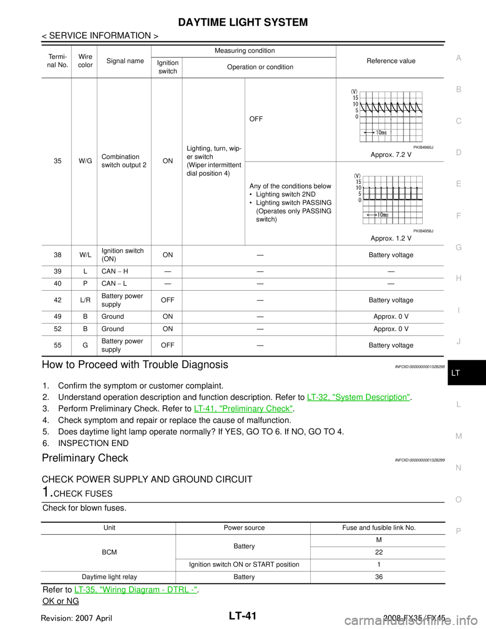
35 W/G Combination
switch output 2 ONLighting, turn, wip-
er switch
(Wiper intermittent
dial position 4) OFF
Approx. 7.2 V
Any of the conditions below
Lighting switch 2ND
Lighting switch PASSING (Operates only PASSING
switch)
Approx. 1.2 V
38 W/L Ignition switch
(ON)
ON — Battery voltage
39 L CAN − H— — —
40 P CAN − L— — —
42 L/R Battery power
supply
OFF — Battery voltage
49 B Ground ON — Approx. 0 V
52 B Ground ON — Approx. 0 V
55 G Battery power
supply OFF — Battery voltage
Te r m i -
nal No. Wire
color Signal name Measuring condition
Reference value
Ignition
switch Operation or condition
PKIB4960J
PKIB4958J
Unit Power source Fuse and fusible link No.
BCM Battery M
22
Ignition switch ON or START position 1
Daytime light relay Battery 36
3AA93ABC3ACD3AC03ACA3AC03AC63AC53A913A773A893A873A873A8E3A773A983AC73AC93AC03AC3
3A893A873A873A8F3A773A9D3AAF3A8A3A8C3A863A9D3AAF3A8B3A8C
Page 3156 of 3924
LT-54
< SERVICE INFORMATION >
AUTO LIGHT SYSTEM
NOTE:
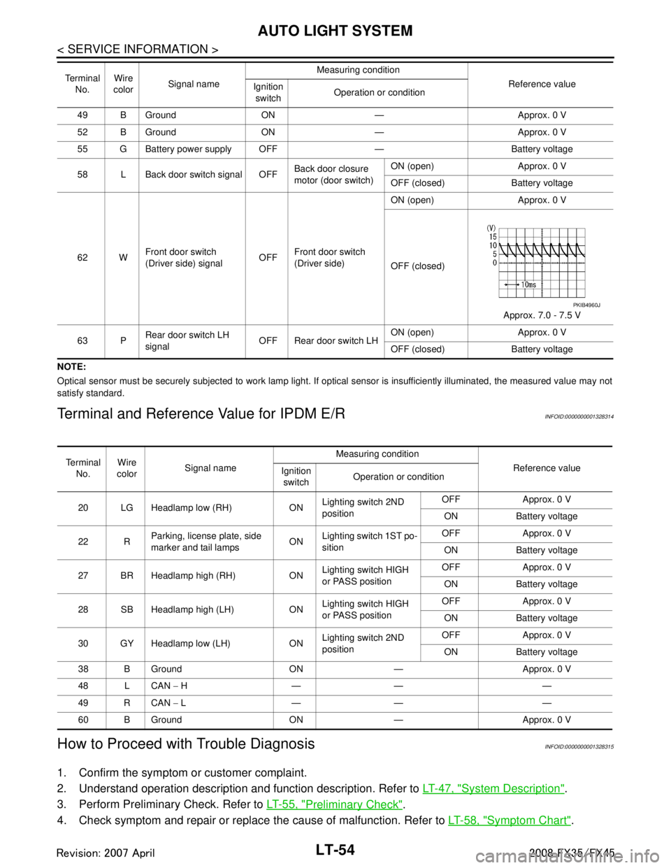
Optical sensor must be securely subjected to work lamp light. If optical sensor is insufficiently illuminated, the measured value may not
satisfy standard.
Terminal and Reference Value for IPDM E/RINFOID:0000000001328314
How to Proceed with Trouble DiagnosisINFOID:0000000001328315
1. Confirm the symptom or customer complaint.
2. Understand operation description and function description. Refer to LT-47, "
System Description".
3. Perform Preliminary Check. Refer to LT-55, "
Preliminary Check".
4. Check symptom and repair or replace the cause of malfunction. Refer to LT-58, "
Symptom Chart".
49 B Ground ON — Approx. 0 V
52 B Ground ON — Approx. 0 V
55 G Battery power supply OFF — Battery voltage
58 L Back door switch signal OFF Back door closure
motor (door switch)ON (open) Approx. 0 V
OFF (closed) Battery voltage
62 W Front door switch
(Driver side) signal OFFFront door switch
(Driver side) ON (open) Approx. 0 V
OFF (closed)
Approx. 7.0 - 7.5 V
63 P Rear door switch LH
signal OFF Rear door switch LH ON (open) Approx. 0 V
OFF (closed) Battery voltage
Te r m i n a l
No. Wire
color Signal name Measuring condition
Reference value
Ignition
switch Operation or condition
PKIB4960J
Te r m i n a l
No. Wire
color Signal name Measuring condition
Reference value
Ignition
switch Operation or condition
20 LG Headlamp low (RH) ON Lighting switch 2ND
positionOFF Approx. 0 V
ON Battery voltage
22 R Parking, license plate, side
marker and tail lamps ON
Lighting switch 1ST po-
sition OFF Approx. 0 V
ON Battery voltage
27 BR Headlamp high (RH) ON Lighting switch HIGH
or PASS positionOFF Approx. 0 V
ON Battery voltage
28 SB Headlamp high (LH) ON Lighting switch HIGH
or PASS positionOFF Approx. 0 V
ON Battery voltage
30 GY Headlamp low (LH) ON Lighting switch 2ND
positionOFF Approx. 0 V
ON Battery voltage
38 B Ground ON — Approx. 0 V
48 L CAN − H—— —
49 R CAN − L—— —
60 B Ground ON — Approx. 0 V
3AA93ABC3ACD3AC03ACA3AC03AC63AC53A913A773A893A873A873A8E3A773A983AC73AC93AC03AC3
3A893A873A873A8F3A773A9D3AAF3A8A3A8C3A863A9D3AAF3A8B3A8C
Page 3173 of 3924
FRONT FOG LAMPLT-71
< SERVICE INFORMATION >
C
DE
F
G H
I
J
L
M A
B
LT
N
O P
How to Proceed with Trouble DiagnosisINFOID:0000000001328334
1. Confirm the symptom or customer complaint.
2. Understand operation description and function description. Refer to LT-66, "
System Description".
3. Perform Preliminary Check. Refer to LT-71, "
Preliminary Check".
4. Check symptom and repair or replace the cause of malfunction.
5. Does front fog lamp operate normally? If YES, GO TO 6. If NO, GO TO 4.
6. INSPECTION END
Preliminary CheckINFOID:0000000001328335
CHECK POWER SUPPLY AND GROUND CIRCUIT
1.CHECK FUSES
Check for blown fuses.
Refer to LT-68, "
Wiring Diagram - F/FOG -".
OK or NG
OK >> GO TO 2.
NG >> If fuse is blown, be sure to eliminate caus e of malfunction before installing new fuse. Refer to PG-
3.
2.CHECK POWER SUPPLY CIRCUIT
38 B Ground ON — Approx. 0 V
48 L CAN − H— — —
49 R CAN − L— — —
60 B Ground ON — Approx. 0 V
Te r m i -
nal
No. Wire
color Signal
name Measuring condition
Reference value
Ignition
switch Operation or condition
Unit Power source Fuse and fusible link No.
BCM Battery
M
22
Ignition switch ON or START position 1 Ignition switch ACC or ON position 6
IPDM E/R Battery 88
3AA93ABC3ACD3AC03ACA3AC03AC63AC53A913A773A893A873A873A8E3A773A983AC73AC93AC03AC3
3A893A873A873A8F3A773A9D3AAF3A8A3A8C3A863A9D3AAF3A8B3A8C
Page 3190 of 3924
LT-88
< SERVICE INFORMATION >
TURN SIGNAL AND HAZARD WARNING LAMPS
How to Proceed with Trouble Diagnosis
INFOID:0000000001328351
1. Confirm the symptom or customer complaint.
2. Understand operation description and function description. Refer to LT-78, "
System Description".
3. Perform preliminary check. Refer to LT-88, "
Preliminary Check".
4. Check symptom and repair or r eplace the cause of malfunction.
5. Do turn signal and hazard warning lamps operate no rmally? If YES, GO TO 6. If NO, GO TO 4.
6. INSPECTION END
Preliminary CheckINFOID:0000000001328352
CHECK POWER SUPPLY AND GROUND CIRCUIT
1.CHECK FUSES
Check for blown fuses.
Refer to LT- 8 2 , "Wiring Diagram - TURN -".
OK or NG
OK >> GO TO 2.
NG >> If fuse is blown, be sure to eliminate caus e of malfunction before installing new fuse. Refer to PG-
3.
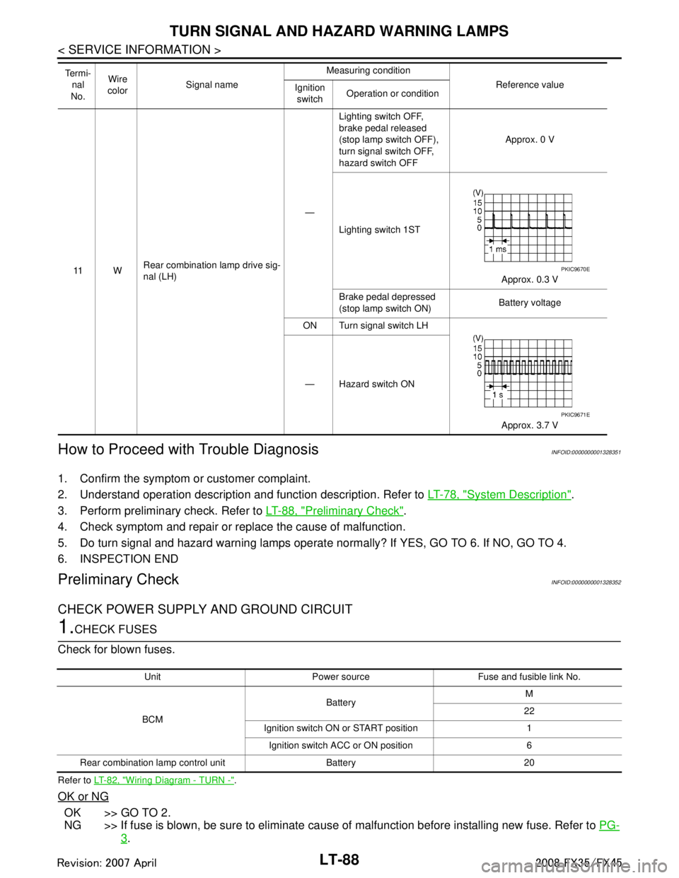
11 WRear combination lamp drive sig-
nal (LH) —Lighting switch OFF,
brake pedal released
(stop lamp switch OFF),
turn signal switch OFF,
hazard switch OFF
Approx. 0 V
Lighting switch 1ST Approx. 0.3 V
Brake pedal depressed
(stop lamp switch ON) Battery voltage
ON Turn signal switch LH
Approx. 3.7 V
— Hazard switch ON
Te r m i -
nal
No. Wire
color Signal name Measuring condition
Reference value
Ignition
switch Operation or conditionPKIC9670E
PKIC9671E
Unit Power source Fuse and fusible link No.
BCM Battery
M
22
Ignition switch ON or START position 1 Ignition switch ACC or ON position 6
Rear combination lamp control unit Battery 20
3AA93ABC3ACD3AC03ACA3AC03AC63AC53A913A773A893A873A873A8E3A773A983AC73AC93AC03AC3
3A893A873A873A8F3A773A9D3AAF3A8A3A8C3A863A9D3AAF3A8B3A8C
Page 3196 of 3924
LT-94
< SERVICE INFORMATION >
TURN SIGNAL AND HAZARD WARNING LAMPS
5. Check continuity between rear combination lamp control unit harness connector B65 terminal 8 and rearcombination lamp RH harness connector B219 terminal 4.
OK or NG
OK >> Replace rear combination lamp control unit or rear combination lamp, and then check if turn signal
lamps is illuminated.
NG >> Repair harness or connector.
Hazard Warning Lamp Does Not Oper ate But Turn Signal Lamp OperatesINFOID:0000000001381754
1.CHECK HAZARD SWITCH INPUT SIGNAL
With CONSULT-III
1. Select “HAZARD SW” of BCM (FLASHER) data monitor item.
2. With operating the hazard switch, check the monitor status.
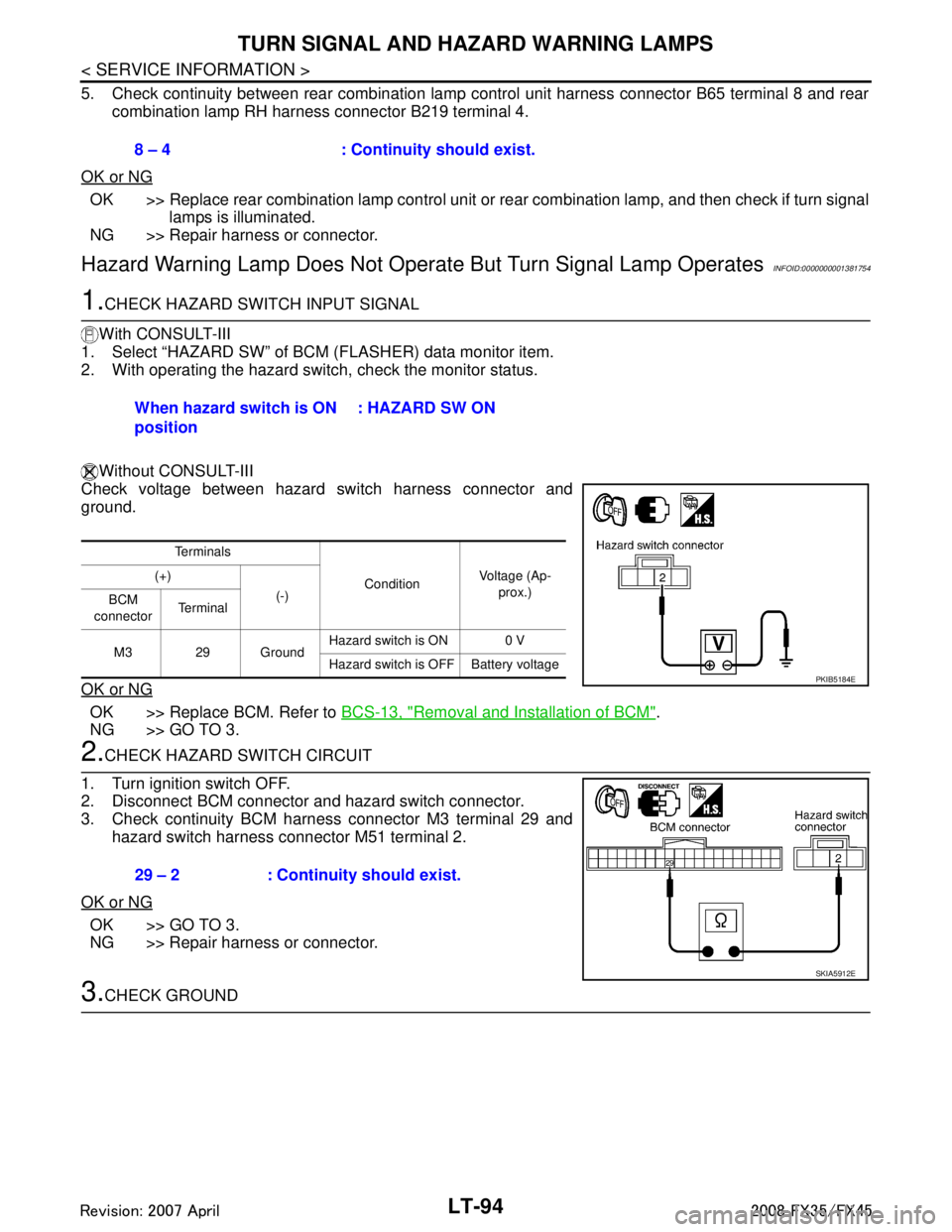
Without CONSULT-III
Check voltage between hazard switch harness connector and
ground.
OK or NG
OK >> Replace BCM. Refer to BCS-13, "Removal and Installation of BCM".
NG >> GO TO 3.
2.CHECK HAZARD SWITCH CIRCUIT
1. Turn ignition switch OFF.
2. Disconnect BCM connector and hazard switch connector.
3. Check continuity BCM harness connector M3 terminal 29 and
hazard switch harness connector M51 terminal 2.
OK or NG
OK >> GO TO 3.
NG >> Repair harness or connector.
3.CHECK GROUND 8 – 4 : Continuity should exist.
When hazard switch is ON
position
: HAZARD SW ON
Te r m i n a l s
ConditionVoltage (Ap-
prox.)
(+)
(-)
BCM
connector Te r m i n a l
M3 29 Ground Hazard switch is ON 0 V
Hazard switch is OFF Battery voltage
PKIB5184E
29 – 2 : Continuity should exist.
SKIA5912E
3AA93ABC3ACD3AC03ACA3AC03AC63AC53A913A773A893A873A873A8E3A773A983AC73AC93AC03AC3
3A893A873A873A8F3A773A9D3AAF3A8A3A8C3A863A9D3AAF3A8B3A8C
Page 3197 of 3924
TURN SIGNAL AND HAZARD WARNING LAMPSLT-95
< SERVICE INFORMATION >
C
DE
F
G H
I
J
L
M A
B
LT
N
O P
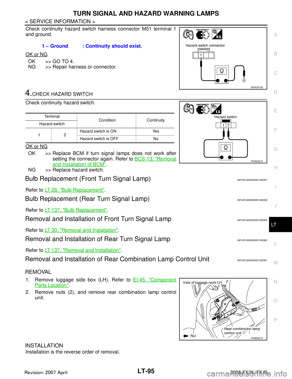
Check continuity hazard switch harness connector M51 terminal 1
and ground.
OK or NG
OK >> GO TO 4.
NG >> Repair harness or connector.
4.CHECK HAZARD SWITCH
Check continuity hazard switch.
OK or NG
OK >> Replace BCM if turn signal lamps does not work after setting the connector again. Refer to BCS-13, "
Removal
and Installation of BCM".
NG >> Replace hazard switch.
Bulb Replacement (Fr ont Turn Signal Lamp)INFOID:0000000001328357
Refer to LT-28, "Bulb Replacement".
Bulb Replacement (Rear Turn Signal Lamp)INFOID:0000000001328358
Refer to LT-137, "Bulb Replacement".
Removal and Installation of Front Turn Signal LampINFOID:0000000001328359
Refer to LT-30, "Removal and Installation".
Removal and Installation of Rear Turn Signal LampINFOID:0000000001328360
Refer to LT-137, "Removal and Installation".
Removal and Installation of Rear Combination Lamp Control UnitINFOID:0000000001328361
REMOVAL
1. Remove luggage side box (LH). Refer to EI-45, "Component
Parts Location".
2. Remove nuts (2), and remove rear combination lamp control unit.
INSTALLATION
Installation is the reverse order of removal. 1 – Ground : Continuity should exist.
SKIA5913E
Te r m i n a l
Condition Continuity
Hazard switch
12 Hazard switch is ON Yes
Hazard switch is OFF No
PKIA5221E
PKIB3631E
3AA93ABC3ACD3AC03ACA3AC03AC63AC53A913A773A893A873A873A8E3A773A983AC73AC93AC03AC3
3A893A873A873A8F3A773A9D3AAF3A8A3A8C3A863A9D3AAF3A8B3A8C