2008 INFINITI FX35 air condition
[x] Cancel search: air conditionPage 2652 of 3924
![INFINITI FX35 2008 Service Manual
EM-168
< SERVICE INFORMATION >[VK45DE]
NOISE, VIBRATION AND HARSHNESS
(NVH) TROUBLESHOOTING
3. Specify the operating condition of engine.
4. Check specified noise source.
If necessary, repair or rep INFINITI FX35 2008 Service Manual
EM-168
< SERVICE INFORMATION >[VK45DE]
NOISE, VIBRATION AND HARSHNESS
(NVH) TROUBLESHOOTING
3. Specify the operating condition of engine.
4. Check specified noise source.
If necessary, repair or rep](/manual-img/42/57017/w960_57017-2651.png)
EM-168
< SERVICE INFORMATION >[VK45DE]
NOISE, VIBRATION AND HARSHNESS
(NVH) TROUBLESHOOTING
3. Specify the operating condition of engine.
4. Check specified noise source.
If necessary, repair or replace these parts.
A: Closely related B: Related C: Sometimes related —: Not relatedLocation
of noise Type of
noise Operating condition of engine
Source of noise Check item
Refer-
ence page
Be-
fore
warm- up After
warm-
up When
start-
ing When
idling When
racing While
driving
Top of en-
gine
Rocker
cover
Cylinder
head Ticking or
clicking
C A — A B — Tappet noise Valve clearance
EM-218
Rattle C A — A B CCamshaft
bearing noiseCamshaft journal oil
clearance
Camshaft runout EM-211EM-211
Crank-
shaft pul-
ley
Cylinder
block
(Side of
engine)
Oil panSlap or
knock
—A—B B— Piston pin
noisePiston to piston pin oil
clearance
Connecting rod bushing
oil clearance EM-256
EM-256
Slap or
rap
A——B B A Piston slap
noisePiston to cylinder bore
clearance
Piston ring side clear-
ance
Piston ring end gap
Connecting rod bend
and torsion EM-256EM-256
EM-256
EM-256
Knock A B C B B B
Connecting
rod bearing
noiseConnecting rod bushing
oil clearance
Connecting rod bearing
oil clearance
EM-256EM-256
Knock A B — A B C
Main bearing
noiseMain bearing oil clear-
ance
Crankshaft runout EM-256EM-256
Front of
engine
front coverTapping or
ticking
AA—BBB Timing chain
and chain
tensioner
noiseTiming chain cracks
and wear
Timing chain tensioner
operation
EM-200
EM-199
Front of
engineSqueak-
ing or fizz-
ing
AB—B—C Drive belts
(Sticking or
slipping)Drive belts deflection
EM-170
Creaking A B A B A B Drive belts
(Slipping)Idler pulley bearing op-
eration
Squall
Creak AB—BAB Water pump
noise
Water pump operation
CO-50
3AA93ABC3ACD3AC03ACA3AC03AC63AC53A913A773A893A873A873A8E3A773A983AC73AC93AC03AC3
3A893A873A873A8F3A773A9D3AAF3A8A3A8C3A863A9D3AAF3A8B3A8C
Page 2655 of 3924
![INFINITI FX35 2008 Service Manual
DRIVE BELTSEM-171
< SERVICE INFORMATION > [VK45DE]
C
D
E
F
G H
I
J
K L
M A
EM
NP
O
3. Under the above condition, insert a metallic bar of
approximately 6 mm (0.24 in) in diameter (hexagonal
bar wren INFINITI FX35 2008 Service Manual
DRIVE BELTSEM-171
< SERVICE INFORMATION > [VK45DE]
C
D
E
F
G H
I
J
K L
M A
EM
NP
O
3. Under the above condition, insert a metallic bar of
approximately 6 mm (0.24 in) in diameter (hexagonal
bar wren](/manual-img/42/57017/w960_57017-2654.png)
DRIVE BELTSEM-171
< SERVICE INFORMATION > [VK45DE]
C
D
E
F
G H
I
J
K L
M A
EM
NP
O
3. Under the above condition, insert a metallic bar of
approximately 6 mm (0.24 in) in diameter (hexagonal
bar wrench shown as example in the figure) through the holding boss to lock auto tensioner pulley arm.
Leave auto tensioner pulley arm locked until belt is installed again.
4. Remove alternator, water pump and A/C compressor belt.
Power Steering Oil Pump Belt
1. Remove air duct (inlet). Refer to EM-173, "Component".
2. Remove front engine undercover with power tool.
3. Remove alternator, water pump and A/C compressor belt. Refer to "Alternator, Water Pump and A/C Compressor Belt".
4. While securely holding the hexagonal protrusion part of auto tensioner pulley with box wrench, move wrench handle in the
direction of arrow (loosening direction of tensioner).
CAUTION:
Avoid placing hand in a locat ion where pinching may occur
if holding tool accidentally comes off.
5. Under the above condition, insert a metallic bar of approximately 6 mm (0.24 in) in diameter (hexagonal bar wrench shown as
example in the figure) through the holding boss to lock auto ten-
sioner pulley arm.
Leave auto tensioner pulley arm locked until belt is installed
again.
6. Remove power steering oil pump belt.
INSTALLATION
Note the following, and install in the reverse order of removal.
CAUTION:
Make sure belt is securely installed around all pulleys.
Make sure belt is correctly engaged with the pulley groove.
Check for engine oil and engine coolan t are not adhered belt and pulley groove.
Check that belt tension is within the allowable working range, using indicator notch on auto ten-
sioner. Refer to EM-170, "
Checking Drive Belts".
ComponentINFOID:0000000001325769
CAUTION:
The complete drive belt auto-tensioner must be replaced as a unit, including the pulley.
PBIC1543E
1.Auto tensioner ( Us
ed for alternator,
water pump and A/C compressor) 2. Idler pulley 3. Auto tensioner (Use
d for power steer-
ing oil pump belt)
PBIC2788E
3AA93ABC3ACD3AC03ACA3AC03AC63AC53A913A773A893A873A873A8E3A773A983AC73AC93AC03AC3
3A893A873A873A8F3A773A9D3AAF3A8A3A8C3A863A9D3AAF3A8B3A8C
Page 2735 of 3924
![INFINITI FX35 2008 Service Manual
CYLINDER BLOCKEM-251
< SERVICE INFORMATION > [VK45DE]
C
D
E
F
G H
I
J
K L
M A
EM
NP
O
*: For the service parts, the grade for fitting cannot be selected between piston pin and connecting rod. (Only INFINITI FX35 2008 Service Manual
CYLINDER BLOCKEM-251
< SERVICE INFORMATION > [VK45DE]
C
D
E
F
G H
I
J
K L
M A
EM
NP
O
*: For the service parts, the grade for fitting cannot be selected between piston pin and connecting rod. (Only](/manual-img/42/57017/w960_57017-2734.png)
CYLINDER BLOCKEM-251
< SERVICE INFORMATION > [VK45DE]
C
D
E
F
G H
I
J
K L
M A
EM
NP
O
*: For the service parts, the grade for fitting cannot be selected between piston pin and connecting rod. (Only “0” grade is a
vailable.) The
information at the shipment from the plant is described as a reference.
The identification grade stamped on each part is the grade for the dimension measured in new condition.
This grade cannot apply to reused parts.
For reused or repaired parts, measure the dimens ion accurately. Determine the grade by comparing the
measurement with the values of each selection table.
For details of the measurement method of each part , the reuse standards, and the selection method of the
selective fitting parts, refer to the text.
HOW TO SELECT PISTON
When New Cylinder Block is Used:
Check the cylinder bore grade (“1”, “2” or “3”) on the rear upper side
between cylinder block banks, and select piston of the same grade.
NOTE:
Piston is available with piston pin as a set for the service part. (Only
“0” grade piston pin is available.)
When Cylinder Block is Reused:
1. Measure the cylinder bore inner diameter. Refer to EM-256, "Inspection After Disassembly".
2. Determine the bore grade by comparing the measurement with the values the “Cylinder bore inner diame-
ter” of the “Piston Selection Table” . Select piston of the same grade.
Piston Selection Table
Selection points Selection parts Selection items Selection methods
Between cylinder block and
crankshaft Main bearing Main bearing grade
(bearing thickness)Determined by match of cylin-
der block bearing housing
grade (inner diameter of hous-
ing) and crankshaft journal
grade (outer diameter of jour-
nal)
Between crankshaft and con-
necting rod Connecting rod bearing Connecting rod bearing grade
(bearing thickness)Combining service grades for
connecting rod big end diame-
ter and crankshaft pin outer di-
ameter determine connecting
rod bearing selection.
Between cylinder block and pis-
ton Piston and piston pin assembly
(Piston is available together
with piston pin as assembly.) Piston grade
(piston skirt diameter)
Piston grade = cylinder bore
grade (inner diameter of bore)
Between piston and connecting
rod* ———
PBIC2371E
PBIC2372E
3AA93ABC3ACD3AC03ACA3AC03AC63AC53A913A773A893A873A873A8E3A773A983AC73AC93AC03AC3
3A893A873A873A8F3A773A9D3AAF3A8A3A8C3A863A9D3AAF3A8B3A8C
Page 2812 of 3924

FRONT FINAL DRIVE ASSEMBLYFFD-21
< SERVICE INFORMATION >
CEF
G H
I
J
K L
M A
B
FFD
N
O P
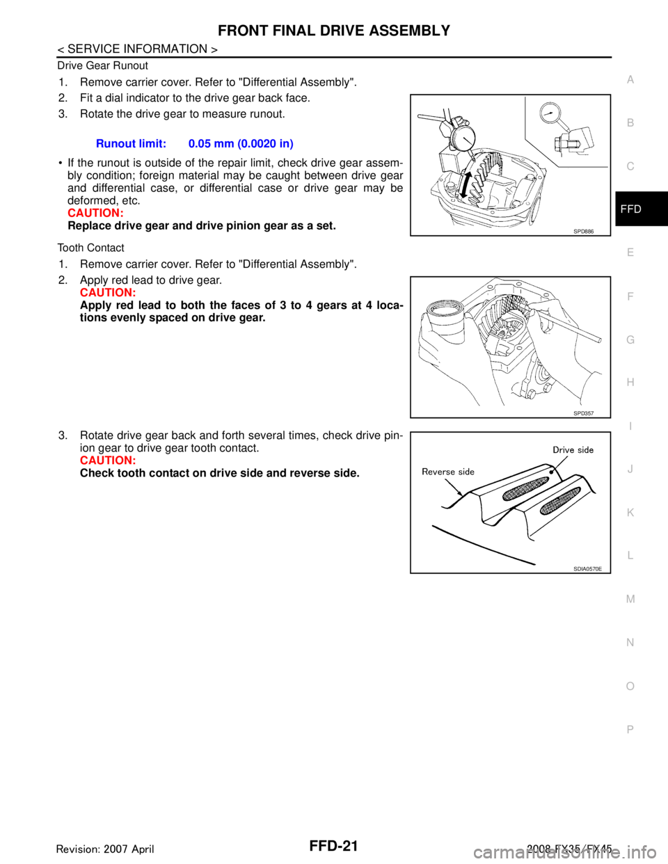
Drive Gear Runout
1. Remove carrier cover. Refer to "Differential Assembly".
2. Fit a dial indicator to the drive gear back face.
3. Rotate the drive gear to measure runout.
If the runout is outside of the repair limit, check drive gear assem-
bly condition; foreign material may be caught between drive gear
and differential case, or differential case or drive gear may be
deformed, etc.
CAUTION:
Replace drive gear and dri ve pinion gear as a set.
Tooth Contact
1. Remove carrier cover. Refer to "Differential Assembly".
2. Apply red lead to drive gear.
CAUTION:
Apply red lead to both the f aces of 3 to 4 gears at 4 loca-
tions evenly spaced on drive gear.
3. Rotate drive gear back and forth several times, check drive pin- ion gear to drive gear tooth contact.
CAUTION:
Check tooth contact on dri ve side and reverse side.
Runout limit: 0.05 mm (0.0020 in)
SPD886
SPD357
SDIA0570E
3AA93ABC3ACD3AC03ACA3AC03AC63AC53A913A773A893A873A873A8E3A773A983AC73AC93AC03AC3
3A893A873A873A8F3A773A9D3AAF3A8A3A8C3A863A9D3AAF3A8B3A8C
Page 2849 of 3924

FRONT SUSPENSION ASSEMBLYFSU-5
< SERVICE INFORMATION >
C
DF
G H
I
J
K L
M A
B
FSU
N
O P
FRONT SUSPENSION ASSEMBLY
On-Vehicle Inspection and ServiceINFOID:0000000001327537
Make sure the mounting conditions (looseness, back lash) of each component and component conditions
(wear, damage) are normal.
INSPECTION LOWER BALL JOINT END PLAY
1. Set front wheels in a straight-ahead position. Do not depress brake pedal.
2. Place an iron bar or similar tool bet ween transverse link and steering knuckle.
3. Measure axial end play by prying it up and down.
CAUTION:
Be careful not to damage ball joint boot.
STRUT INSPECTION
Check strut for oil leakage, damage and replace if there are. Refer to FSU-10.
Wheel Alignment InspectionINFOID:0000000001327538
DESCRIPTION
Measure wheel alignment under unladen conditions.
NOTE:
Unladen conditions mean that fuel, engine coolant, and l ubricant are full. Spare tire, jack, hand tools and
mats are designated positions.
PRELIMINARY CHECK
Check tires for improper air pressure and wear.
Check road wheels for runout.
Check wheel bearing axial end play.
Check ball joint axial end play of compression rod, upper link, and steering knuckle
Check shock absorber operation.
Check each mounting part of axle and suspension for looseness and deformation.
Check each link, rod and member for cracks, deformation and other damage.
Check vehicle posture.
GENERAL INFORMATION AND RECOMMENDATIONS
A four-wheel thrust alignment should be performed.
- This type of alignment is recomm ended for any NISSAN/INFINITI vehicle.
- The four-wheel “thrust” process helps ensure that t he vehicle is properly aligned and the steering wheel is
centered.
- The alignment rack itself should be capable of accepting any NISSAN/INFINITI vehicle.
- The rack should be checked to ensure that it is level.
Make sure the machine is properly calibrated.
- Your alignment equipment should be regularly ca librated in order to give correct information.
- Check with the manufacturer of your specific equi pment for their recommended Service/Calibration Sched-
ule.
THE ALIGNMENT PROCESS
IMPORTANT:
Use only the alignment specificati ons listed in this Service Manual.
When displaying the alignment settings, many alignment machines use “indicators”: (Green/red, plus or
minus, Go/No Go). Do NOT use these indicators.
- The alignment specifications programmed into your machine that operate these indicators may not be cor-
rect.
- This may result in an ERROR.
Some newer alignment machines are equipped with an optional “Rolling Compensation” method to “com-
pensate” the sensors (alignment targets or head units). DO NOT use this “Rolling Compensation”
method. Axial end play : 0 mm (0 in)
3AA93ABC3ACD3AC03ACA3AC03AC63AC53A913A773A893A873A873A8E3A773A983AC73AC93AC03AC3
3A893A873A873A8F3A773A9D3AAF3A8A3A8C3A863A9D3AAF3A8B3A8C
Page 2863 of 3924

GI-1
GENERAL INFORMATION
C
DE
F
G H
I
J
K L
M B
GI
SECTION GI
N
O P
CONTENTS
GENERAL INFORMATION
SERVICE INFORMATION .. ..........................2
PRECAUTIONS .............................................. .....2
Description .......................................................... ......2
Precaution for Supplemental Restraint System
(SRS) "AIR BAG" and "SEAT BELT PRE-TEN-
SIONER" ...................................................................
2
Precaution Necessary for Steering Wheel Rota-
tion After Battery Disconnect .....................................
2
Precaution for Procedure without Cowl Top Cover ......3
General Precaution ...................................................3
Precaution for Three Way Catalyst ...........................4
Precaution for Fuel (Unleaded Premium Gasoline
Recommended) .........................................................
5
Precaution for Fuel (Unleaded Premium Gasoline
Required) ..................................................................
5
Precaution for Multiport Fuel Injection System or
Engine Control System .............................................
5
Precaution for Hoses .................................................5
Precaution for Engine Oils ........................................6
Precaution for the Environment .................................7
Precaution for Air Conditioning .................................7
HOW TO USE THIS MANUAL ............................8
Description .......................................................... ......8
Terms ........................................................................8
Units ..........................................................................8
Contents ....................................................................8
Component ................................................................8
How to Follow Trouble Diagnosis ..............................9
How to Read Wiring Diagram ..................................13
Abbreviations ..........................................................20
SERVICE INFORMATION FOR ELECTRICAL
INCIDENT ...........................................................
22
How to Check Terminal ....................................... ....22
How to Perform Efficient Diagnosis for an Electri-
cal Incident .......................................................... ....
25
Control Units and Electrical Parts ............................32
CONSULT-III/GST CHECKING SYSTEM .........34
Description ...............................................................34
CONSULT-III Function and System Application*1 ....34
CONSULT-III/GST Data Link Connector (DLC)
Circuit ......................................................................
35
Wiring Diagram - CONSULT-III/GST CHECKING
SYSTEM - ................................................................
36
LIFTING POINT .................................................37
Commercial Service Tool ........................................37
Garage Jack and Safety Stand ................................37
2-Pole Lift ................................................................38
Board-On Lift ...........................................................38
TOW TRUCK TOWING .....................................40
Tow Truck Towing ...................................................40
Vehicle Recovery (Freeing a Stuck Vehicle) ...........41
TIGHTENING TORQUE OF STANDARD
BOLTS ...............................................................
43
Tightening Torque Table .........................................43
RECOMMENDED CHEMICAL PRODUCTS
AND SEALANTS ...............................................
44
Recommended Chemical Product and Sealant .......44
IDENTIFICATION INFORMATION ....................45
Model Variation ........................................................45
Dimensions ..............................................................47
Wheels & Tires ........................................................47
TERMINOLOGY ................................................48
SAE J1930 Terminology List ...................................48
3AA93ABC3ACD3AC03ACA3AC03AC63AC53A913A773A893A873A873A8E3A773A983AC73AC93AC03AC3
3A893A873A873A8F3A773A9D3AAF3A8A3A8C3A863A9D3AAF3A8B3A8C
Page 2869 of 3924

PRECAUTIONSGI-7
< SERVICE INFORMATION >
C
DE
F
G H
I
J
K L
M B
GI
N
O P
Heavily soiled clothing and oil-impregnated footwear should not be worn. Overalls must be cleaned regu-
larly.
First aid treatment should be obtai ned immediately for open cuts and wounds.
Use barrier creams, applying them before each work period, to help the removal of oil from the skin.
Wash with soap and water to ensure all oil is removed (skin cleansers and nail brushes will help). Prepara- tions containing lanolin replace the natural skin oils which have been removed.
Do not use gasoline, kerosene, diesel fuel, gas oil, thinners or solvents for cleaning skin.
If skin disorders develop, obtain medical advice without delay.
Where practical, degrease components prior to handling.
Where there is a risk of eye contact, eye protecti on should be worn, for example, chemical goggles or face
shields; in addition an eye wash facility should be provided.
Precaution for the EnvironmentINFOID:0000000001325661
In servicing the vehicle, it may be necessary to use, dispose of or recycle hazardous, flammable, or poisonous
materials, such as gasoline, refrigerant gas, solvents, oil, oil filter, air bag modules, seat belt pretensioners,
etc. Disposal, recycling, and transportation of any haz ardous materials should be performed in compliance
with applicable federal, state and local laws and regulations.
Precaution for Air ConditioningINFOID:0000000001325662
Use an approved refrigerant recovery unit any time t he air conditioning system must be discharged. Refer to
ATC/MTC section “HFC-134a (R-134a) Service Procedure”, “REFRIGERANT LINES” for specific instructions.
3AA93ABC3ACD3AC03ACA3AC03AC63AC53A913A773A893A873A873A8E3A773A983AC73AC93AC03AC3
3A893A873A873A8F3A773A9D3AAF3A8A3A8C3A863A9D3AAF3A8B3A8C
Page 2882 of 3924

GI-20
< SERVICE INFORMATION >
HOW TO USE THIS MANUAL
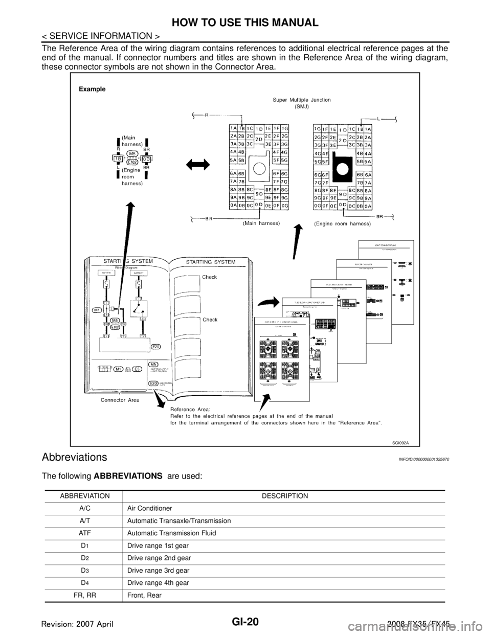
The Reference Area of the wiring diagram contains references to additional electrical reference pages at the
end of the manual. If connector numbers and titles are s hown in the Reference Area of the wiring diagram,
these connector symbols are not shown in the Connector Area.
AbbreviationsINFOID:0000000001325670
The following ABBREVIATIONS are used:
SGI092A
ABBREVIATION DESCRIPTION
A/C Air ConditionerA/T Automatic Transaxle/Transmission
ATF Automatic Transmission Fluid D
1Drive range 1st gear
D
2Drive range 2nd gear
D
3Drive range 3rd gear
D
4Drive range 4th gear
FR, RR Front, Rear
3AA93ABC3ACD3AC03ACA3AC03AC63AC53A913A773A893A873A873A8E3A773A983AC73AC93AC03AC3
3A893A873A873A8F3A773A9D3AAF3A8A3A8C3A863A9D3AAF3A8B3A8C