2008 INFINITI FX35 radiator cap
[x] Cancel search: radiator capPage 2271 of 3924
![INFINITI FX35 2008 Service Manual
DTC P1217 ENGINE OVER TEMPERATUREEC-1031
< SERVICE INFORMATION > [VK45DE]
C
D
E
F
G H
I
J
K L
M A
EC
NP
O
COMPONENT DESCRIPTION
Cooling Fan Motor
The cooling fan at each speed when the current
flows INFINITI FX35 2008 Service Manual
DTC P1217 ENGINE OVER TEMPERATUREEC-1031
< SERVICE INFORMATION > [VK45DE]
C
D
E
F
G H
I
J
K L
M A
EC
NP
O
COMPONENT DESCRIPTION
Cooling Fan Motor
The cooling fan at each speed when the current
flows](/manual-img/42/57017/w960_57017-2270.png)
DTC P1217 ENGINE OVER TEMPERATUREEC-1031
< SERVICE INFORMATION > [VK45DE]
C
D
E
F
G H
I
J
K L
M A
EC
NP
O
COMPONENT DESCRIPTION
Cooling Fan Motor
The cooling fan at each speed when the current
flows in the cooling fan motor as follows.
CONSULT-III Reference Value in Data Monitor ModeINFOID:0000000001326897
Specification data are reference values.
On Board Diagnosis LogicINFOID:0000000001326898
If the cooling fan or another component in the cooling system malfunctions, engine coolant temperature will
rise.
When the engine coolant temperature reaches an abnorma lly high temperature condition, a malfunction is
indicated.
This self-diagnosis has the on e trip detection logic.
CAUTION:
When a malfunction is in dicated, be sure to replace the coolant. Refer to CO-37, "
Changing Engine
Coolant". Also, replace the engine oil. Refer to LU-24, "Changing Engine Oil".
1. Fill radiator with coolant up to specified level with a filling speed of 2 liters per minute. Be sure to
use coolant with the proper mixture ratio. Refer to MA-10, "
Anti-Freeze Coolant Mixture Ratio".
Cooling fan speed Cooling fan relay
13
Stop (OFF) OFF OFF
Middle (MID) OFF ON
High (HI) ON ON
Cooling fan speed Cooling fan motor terminals
(+) (-)
Middle (MID) 1 3 and 4
2 3 and 4
High (HI) 1 and 2 3 and 4
MONITOR ITEM CONDITION SPECIFICATION
COOLING FAN Engine: After warming up, idle the
engine
Air conditioner switch: OFF Engine coolant temperature is 94
°C
(201 °F) or less OFF
Engine coolant temperature is between
95 °C (203 °F) and 104 °C (219 °F) MID
Engine coolant temperature is 105 °C
(221 °F) or more HI
DTC No. Trouble diagnosis name DTC detecting condition Possible cause
P1217
1217 Engine over tempera-
ture (Overheat) Cooling fan does not operate properly (Over-
heat).
Cooling fan system does not operate proper- ly (Overheat).
Engine coolant was not added to the system using the proper filling method.
Engine coolant is not within the specified
range. Harness or connectors
(The cooling fan circuit is open or short-
ed.)
IPDM E/R
Cooling fan
Radiator hose
Radiator
Radiator cap
Water pump
Thermostat
Water control valve
For more informat ion, refer to EC-1039,
"Main 13 Causes of Overheating".
3AA93ABC3ACD3AC03ACA3AC03AC63AC53A913A773A893A873A873A8E3A773A983AC73AC93AC03AC3
3A893A873A873A8F3A773A9D3AAF3A8A3A8C3A863A9D3AAF3A8B3A8C
Page 2272 of 3924
![INFINITI FX35 2008 Service Manual
EC-1032
< SERVICE INFORMATION >[VK45DE]
DTC P1217 ENGINE
OVER TEMPERATURE
2. After refilling coolant, run engine to en sure that no water-flow noise is emitted.
Overall Function CheckINFOID:00000000 INFINITI FX35 2008 Service Manual
EC-1032
< SERVICE INFORMATION >[VK45DE]
DTC P1217 ENGINE
OVER TEMPERATURE
2. After refilling coolant, run engine to en sure that no water-flow noise is emitted.
Overall Function CheckINFOID:00000000](/manual-img/42/57017/w960_57017-2271.png)
EC-1032
< SERVICE INFORMATION >[VK45DE]
DTC P1217 ENGINE
OVER TEMPERATURE
2. After refilling coolant, run engine to en sure that no water-flow noise is emitted.
Overall Function CheckINFOID:0000000001326899
Use this procedure to check the overall function of the cooling fan. During this check, a DTC might not be con-
firmed.
WARNING:
Never remove the radiator cap when the engine is hot. Serious burns could be caused by high pres-
sure fluid escaping from the radiator.
Wrap a thick cloth around cap. Carefully remove the cap by turning it a quarter turn to allow built-up
pressure to escape. Then turn the cap all the way off.
WITH CONSULT-III
1. Check the coolant level in the reservoir tank and radiator. Allow engine to cool before checking coolant level.
If the coolant level in the reservoir tank and/or radiator is below
the proper range, skip the following steps and go to EC-1035,
"Diagnosis Procedure".
2. Confirm whether customer filled the coolant or not. If customer
filled the coolant, skip the following steps and go to EC-1035,
"Diagnosis Procedure".
3. Turn ignition switch ON.
4. Perform “COOLING FAN” in “ACTIVE TEST” mode with CON- SULT-III.
5. If the results are NG, go to EC-1035, "
Diagnosis Procedure".
WITH GST
1. Check the coolant level in the reservoir tank and radiator.
Allow engine to cool before checking coolant level.
If the coolant level in the reservoir tank and/or radiator is below
the proper range, skip the following steps and go to EC-1035,
"Diagnosis Procedure".
2. Confirm whether customer filled the coolant or not. If customer
filled the coolant, skip the following steps and go to EC-1035,
"Diagnosis Procedure".
3. Disconnect engine coolant temperature sensor harness connec- tor.
4. Connect 200 Ω resister to the engine coolant temperature sensor
harness connector.
5. Start engine and make sure that cooling fan operates at middle speed.
Be careful not to overheat engine.
If NG, go to EC-1035, "
Diagnosis Procedure".
If OK, go to the following step.
6. Turn ignition switch OFF.
7. Disconnect 200 Ω resister from engine coolant temperature sen-
sor harness connector.
8. Connect 150 Ω resistor to engine coolant temperature sensor
harness connector.
SEF621W
SEF621W
PBIB0965E
3AA93ABC3ACD3AC03ACA3AC03AC63AC53A913A773A893A873A873A8E3A773A983AC73AC93AC03AC3
3A893A873A873A8F3A773A9D3AAF3A8A3A8C3A863A9D3AAF3A8B3A8C
Page 2277 of 3924
![INFINITI FX35 2008 Service Manual
DTC P1217 ENGINE OVER TEMPERATUREEC-1037
< SERVICE INFORMATION > [VK45DE]
C
D
E
F
G H
I
J
K L
M A
EC
NP
O
Apply pressure to the cooling sys
tem with a tester, and check if the
pressure drops.
CAUTION INFINITI FX35 2008 Service Manual
DTC P1217 ENGINE OVER TEMPERATUREEC-1037
< SERVICE INFORMATION > [VK45DE]
C
D
E
F
G H
I
J
K L
M A
EC
NP
O
Apply pressure to the cooling sys
tem with a tester, and check if the
pressure drops.
CAUTION](/manual-img/42/57017/w960_57017-2276.png)
DTC P1217 ENGINE OVER TEMPERATUREEC-1037
< SERVICE INFORMATION > [VK45DE]
C
D
E
F
G H
I
J
K L
M A
EC
NP
O
Apply pressure to the cooling sys
tem with a tester, and check if the
pressure drops.
CAUTION:
Higher than the specified pressu re may cause radiator damage.
Pressure should not drop.
OK or NG
OK >> GO TO 7.
NG >> Check the following for leak. Refer to CO-37, "
Inspec-
tion".
Hose
Radiator
Water pump
7.CHECK RADIATOR CAP
Apply pressure to cap with a tester.
OK or NG
OK >> GO TO 8.
NG >> Replace radiator cap.
8.CHECK COMPONENT PARTS
Check the following.
Thermostat. (Refer to CO-52
.)
Water control valve. (Refer to CO-52
.)
Engine coolant temperature sensor. (Refer to EC-783, "
Component Inspection".)
OK or NG
OK >> GO TO 9.
NG >> Replace malfunctioning component.
9.CHECK MAIN 13 CAUSES
If the cause cannot be isolated, go to EC-1039, "
Main 13 Causes of Overheating".
>> INSPECTION END
PROCEDURE A
1.CHECK POWER SUPPLY CIRCUIT
1. Turn ignition switch OFF.
2. Disconnect IPDM E/R harness connector E6.
3. Check voltage between IPDM E/R terminal 16 and ground with CONSULT-III or tester.
OK or NG
OK >> GO TO 3.
NG >> GO TO 2. Testing pressure: 157 kPa (1.6 kg/cm
2, 23 psi)
PBIC1528E
Radiator cap
relief pressure:
59 - 98 kPa (0.6 - 1.0 kg/cm2, 9 - 14 psi)
SLC755A
Voltage: Battery voltage
PBIB0966E
3AA93ABC3ACD3AC03ACA3AC03AC63AC53A913A773A893A873A873A8E3A773A983AC73AC93AC03AC3
3A893A873A873A8F3A773A9D3AAF3A8A3A8C3A863A9D3AAF3A8B3A8C
Page 2279 of 3924
![INFINITI FX35 2008 Service Manual
DTC P1217 ENGINE OVER TEMPERATUREEC-1039
< SERVICE INFORMATION > [VK45DE]
C
D
E
F
G H
I
J
K L
M A
EC
NP
O
2. Disconnect cooling fan motor harness connector.
3. Check harness continuity between coolin INFINITI FX35 2008 Service Manual
DTC P1217 ENGINE OVER TEMPERATUREEC-1039
< SERVICE INFORMATION > [VK45DE]
C
D
E
F
G H
I
J
K L
M A
EC
NP
O
2. Disconnect cooling fan motor harness connector.
3. Check harness continuity between coolin](/manual-img/42/57017/w960_57017-2278.png)
DTC P1217 ENGINE OVER TEMPERATUREEC-1039
< SERVICE INFORMATION > [VK45DE]
C
D
E
F
G H
I
J
K L
M A
EC
NP
O
2. Disconnect cooling fan motor harness connector.
3. Check harness continuity between cooling fan motor terminal 1
and IPDM E/R terminal 11.
Refer to wiring diagram.
4. Also check harness for short to ground and short to power.
OK or NG
OK >> GO TO 2.
NG >> Repair open circuit or short to ground or short to power in harness or connectors.
2.CHECK COOLING FAN MOTOR
Refer to EC-1040, "
Component Inspection".
OK or NG
OK >> GO TO 3.
NG >> Replace cooling fan motor.
3.CHECK INTERMITTENT INCIDENT
Perform EC-717
.
OK or NG
OK >> Replace IPDM E/R. Refer to PG-17.
NG >> Repair or replace harness connectors.
Main 13 Causes of OverheatingINFOID:0000000001326902
Continuity should exist.
PBIB1493E
Engine Step Inspection item Equipment Standard Reference page
OFF 1 Blocked radiator Blocked condenser
Blocked radiator grille
Blocked bumper Visual No blocking —
2 Coolant mixture Coolant tester 50 - 50% coolant mixture MA-10
3 Coolant level Visual Coolant up to MAX level in
reservoir tank and radiator
filler neckCO-37
4 Radiator cap Pressure tester 59 - 98 kPa
(0.6 - 1.0 kg/cm2, 9 - 14
psi) (Limit) CO-42
ON*25 Coolant leaks Visual No leaks
CO-37
ON*26 Thermostat Touch the upper and
lower radiator hosesBoth hoses should be hot
CO-52
ON*17 Cooling fan CONSULT-III Operating See trouble diagnosis for
DTC P1217 (EC-1030
).
OFF 8 Combustion gas leak Color checker chemical tester 4 Gas analyzerNegative —
ON*
39 Coolant temperature gauge Visual Gauge less than 3/4 when
driving —
Coolant overflow to res- ervoir tank Visual No overflow during driving
and idling CO-37
OFF*410 Coolant return from res-
ervoir tank to radiator Visual Should be initial level in
reservoir tank CO-37
OFF 11 Water control valve Remove and inspect
the valveWithin the specified value
CO-52
3AA93ABC3ACD3AC03ACA3AC03AC63AC53A913A773A893A873A873A8E3A773A983AC73AC93AC03AC3
3A893A873A873A8F3A773A9D3AAF3A8A3A8C3A863A9D3AAF3A8B3A8C
Page 2866 of 3924

GI-4
< SERVICE INFORMATION >
PRECAUTIONS
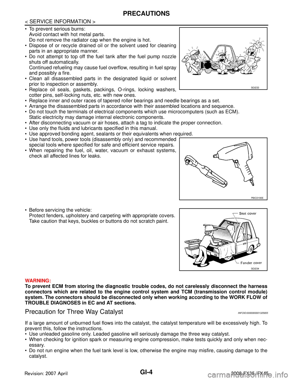
To prevent serious burns:Avoid contact with hot metal parts.
Do not remove the radiator cap when the engine is hot.
Dispose of or recycle drained oil or the solvent used for cleaning parts in an appropriate manner.
Do not attempt to top off the fuel tank after the fuel pump nozzle
shuts off automatically.
Continued refueling may cause fuel overflow, resulting in fuel spray
and possibly a fire.
Clean all disassembled parts in the designated liquid or solvent prior to inspection or assembly.
Replace oil seals, gaskets, packings, O-rings, locking washers, cotter pins, self-locking nuts, etc. with new ones.
Replace inner and outer races of tapered roller bearings and needle bearings as a set.
Arrange the disassembled parts in accordance with their assembled locations and sequence.
Do not touch the terminals of electrical com ponents which use microcomputers (such as ECM).
Static electricity may damage internal electronic components.
After disconnecting vacuum or air hoses, atta ch a tag to indicate the proper connection.
Use only the fluids and lubricants specified in this manual.
Use approved bonding agent, sealants or their equivalents when required.
Use hand tools, power tools (disassembly only) and recommended special tools where specified for safe and efficient service repairs.
When repairing the fuel, oil, water, vacuum or exhaust systems,
check all affected lines for leaks.
Before servicing the vehicle: Protect fenders, upholstery and carpeting with appropriate covers.
Take caution that keys, buckles or buttons do not scratch paint.
WARNING:
To prevent ECM from storing the diagnostic tro uble codes, do not carelessly disconnect the harness
connectors which are related to the engine cont rol system and TCM (transmission control module)
system. The connectors should be disconnected on ly when working according to the WORK FLOW of
TROUBLE DIAGNOSES in EC and AT sections.
Precaution for Three Way CatalystINFOID:0000000001325655
If a large amount of unburned fuel flows into the catalyst , the catalyst temperature will be excessively high. To
prevent this, follow the instructions.
Use unleaded gasoline only. Leaded gasoline will seriously damage the three way catalyst.
When checking for ignition spark or measuring engine compression, make tests quickly and only when nec- essary.
Do not run engine when the fuel tank level is low, otherwise the engine may misfire, causing damage to the
catalyst.
SGI233
PBIC0190E
SGI234
3AA93ABC3ACD3AC03ACA3AC03AC63AC53A913A773A893A873A873A8E3A773A983AC73AC93AC03AC3
3A893A873A873A8F3A773A9D3AAF3A8A3A8C3A863A9D3AAF3A8B3A8C
Page 3131 of 3924

HEADLAMP - XENON TYPE -LT-29
< SERVICE INFORMATION >
C
DE
F
G H
I
J
L
M A
B
LT
N
O P
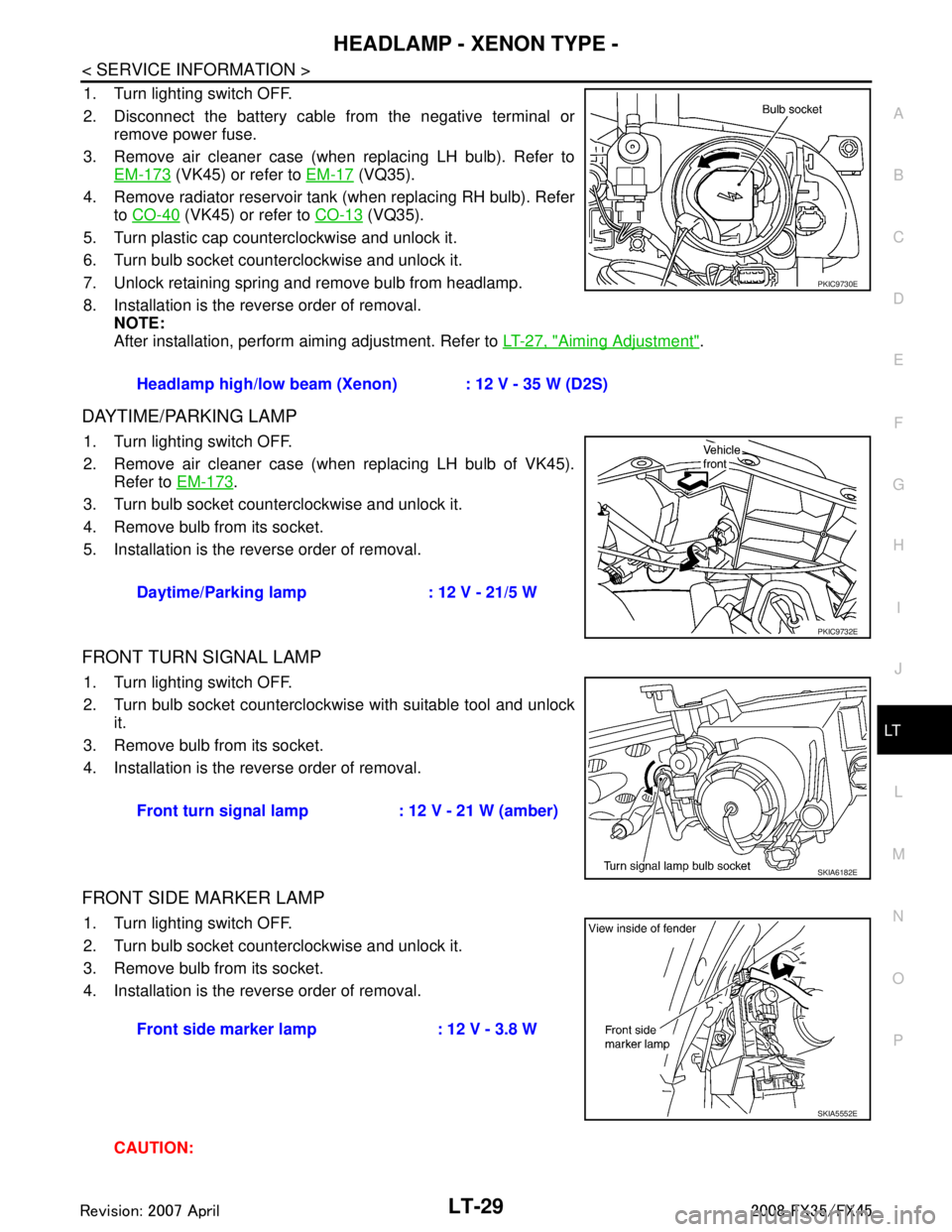
1. Turn lighting switch OFF.
2. Disconnect the battery cable from the negative terminal or remove power fuse.
3. Remove air cleaner case (when replacing LH bulb). Refer to EM-173
(VK45) or refer to EM-17 (VQ35).
4. Remove radiator reservoir tank (when replacing RH bulb). Refer to CO-40
(VK45) or refer to CO-13 (VQ35).
5. Turn plastic cap counterclockwise and unlock it.
6. Turn bulb socket counterclockwise and unlock it.
7. Unlock retaining spring and remove bulb from headlamp.
8. Installation is the reverse order of removal. NOTE:
After installation, perform aiming adjustment. Refer to LT-27, "
Aiming Adjustment".
DAYTIME/PARKING LAMP
1. Turn lighting switch OFF.
2. Remove air cleaner case (when replacing LH bulb of VK45).
Refer to EM-173
.
3. Turn bulb socket counterclockwise and unlock it.
4. Remove bulb from its socket.
5. Installation is the reverse order of removal.
FRONT TURN SIGNAL LAMP
1. Turn lighting switch OFF.
2. Turn bulb socket counterclockwise with suitable tool and unlock it.
3. Remove bulb from its socket.
4. Installation is the reverse order of removal.
FRONT SIDE MARKER LAMP
1. Turn lighting switch OFF.
2. Turn bulb socket counterclockwise and unlock it.
3. Remove bulb from its socket.
4. Installation is the reverse order of removal.
CAUTION:Headlamp high/low beam (Xenon) : 12 V - 35 W (D2S)
PKIC9730E
Daytime/Parking lamp : 12 V - 21/5 W
PKIC9732E
Front turn signal lamp : 12 V - 21 W (amber)
SKIA6182E
Front side marker lamp : 12 V - 3.8 W
SKIA5552E
3AA93ABC3ACD3AC03ACA3AC03AC63AC53A913A773A893A873A873A8E3A773A983AC73AC93AC03AC3
3A893A873A873A8F3A773A9D3AAF3A8A3A8C3A863A9D3AAF3A8B3A8C
Page 3329 of 3924

MA-12
< SERVICE INFORMATION >
ENGINE MAINTENANCE (VQ35DE ENGINE)
When belt is replaced with a new one, adjust it to value for “New belt” to accommodate for insuffi-
cient adaptability with pulley grooves.
When deflection or tension of belt being used exceeds “Limit”, adjust it to value for “After adjust-
ment”.
When checking belt deflection or te nsion immediately after installation, first adjust it to the specified
value. Then, after turning crankshaft two turns or mo re, re-adjust to the specified value to avoid vari-
ation in deflection between pulleys.
When installing belt, make sure that it is correctly engaged with pulley grooves.
Keep engine oil, working fluid and engine coolant away from belt and pulley grooves.
Do not twist or bend belt excessively.
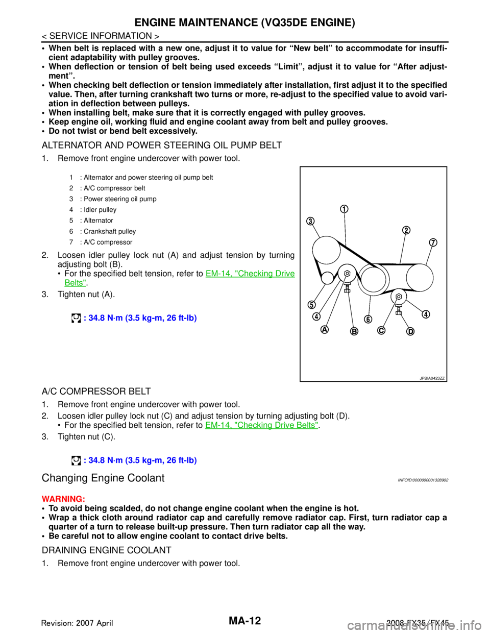
ALTERNATOR AND POWER STEERING OIL PUMP BELT
1. Remove front engine undercover with power tool.
2. Loosen idler pulley lock nut (A) and adjust tension by turning adjusting bolt (B).
For the specified belt tension, refer to EM-14, "
Checking Drive
Belts".
3. Tighten nut (A).
A/C COMPRESSOR BELT
1. Remove front engine undercover with power tool.
2. Loosen idler pulley lock nut (C) and adjust tension by turning adjusting bolt (D). For the specified belt tension, refer to EM-14, "
Checking Drive Belts".
3. Tighten nut (C).
Changing Engine CoolantINFOID:0000000001328902
WARNING:
To avoid being scalded, do not change en gine coolant when the engine is hot.
Wrap a thick cloth around radiator cap and carefully remove radiator cap. First, turn radiator cap a
quarter of a turn to release built-up pressu re. Then turn radiator cap all the way.
Be careful not to allow engine coolant to contact drive belts.
DRAINING ENGINE COOLANT
1. Remove front engine undercover with power tool.
1 : Alternator and power steering oil pump belt
2: A/C compressor belt
3 : Power steering oil pump
4 : Idler pulley
5 : Alternator
6 : Crankshaft pulley
7: A/C compressor
: 34.8 N·m (3.5 kg-m, 26 ft-lb)
JPBIA0423ZZ
: 34.8 N·m (3.5 kg-m, 26 ft-lb)
3AA93ABC3ACD3AC03ACA3AC03AC63AC53A913A773A893A873A873A8E3A773A983AC73AC93AC03AC3
3A893A873A873A8F3A773A9D3AAF3A8A3A8C3A863A9D3AAF3A8B3A8C
Page 3330 of 3924

ENGINE MAINTENANCE (VQ35DE ENGINE)MA-13
< SERVICE INFORMATION >
C
DE
F
G H
I
J
K
M A
B
MA
N
O P
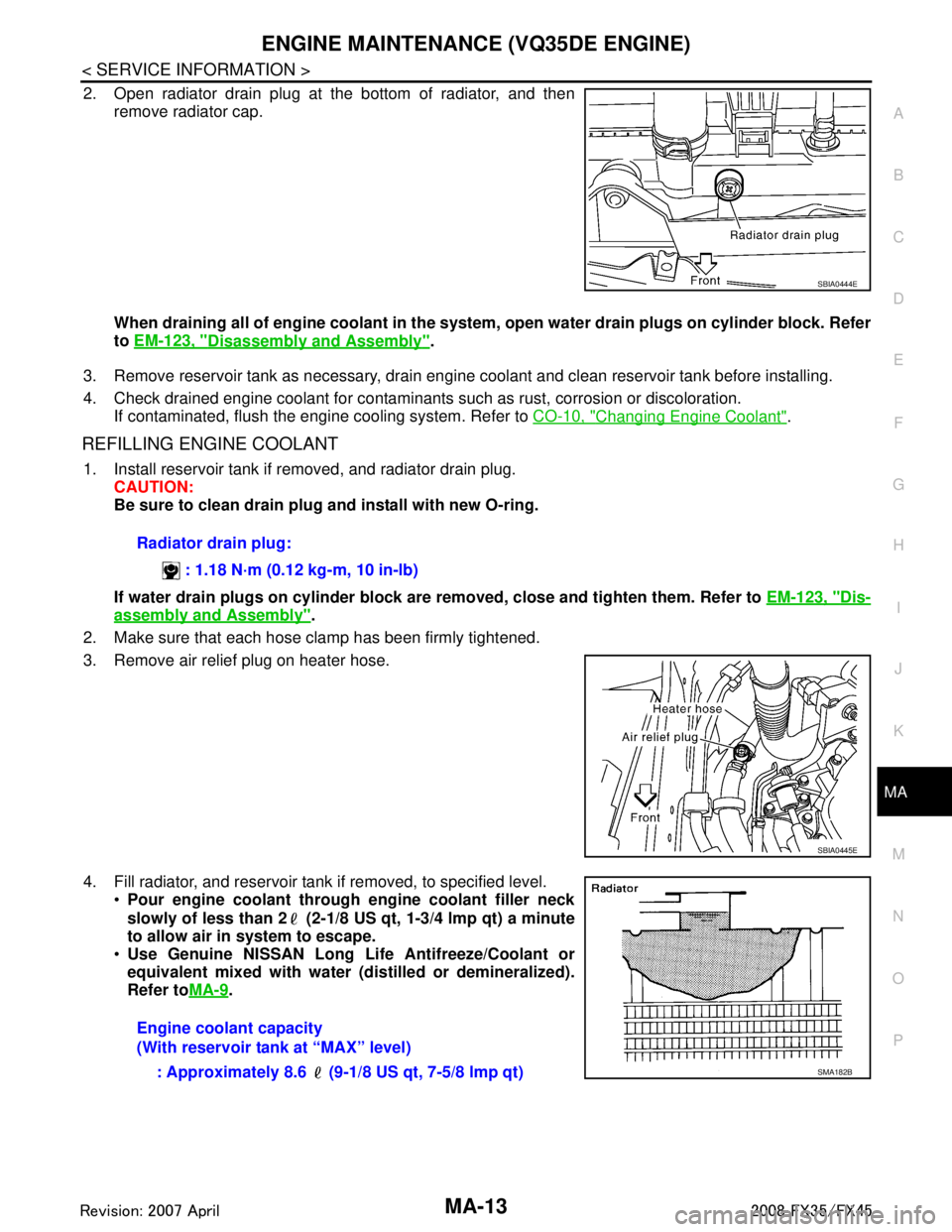
2. Open radiator drain plug at the bottom of radiator, and then
remove radiator cap.
When draining all of engine coolant in the system , open water drain plugs on cylinder block. Refer
to EM-123, "
Disassembly and Assembly".
3. Remove reservoir tank as necessary, drain engine coolant and clean reservoir tank before installing.
4. Check drained engine coolant for contaminants such as rust, corrosion or discoloration. If contaminated, flush the engine cooling system. Refer to CO-10, "
Changing Engine Coolant".
REFILLING ENGINE COOLANT
1. Install reservoir tank if removed, and radiator drain plug.
CAUTION:
Be sure to clean drain plug and install with new O-ring.
If water drain plugs on cylinder block are removed, close and tighten them. Refer to EM-123, "
Dis-
assembly and Assembly".
2. Make sure that each hose clamp has been firmly tightened.
3. Remove air relief plug on heater hose.
4. Fill radiator, and reservoir tank if removed, to specified level. Pour engine coolant through engine coolant filler neck
slowly of less than 2 (2-1/8 US qt, 1-3/4 lmp qt) a minute
to allow air in system to escape.
Use Genuine NISSAN Long Li fe Antifreeze/Coolant or
equivalent mixed with water (dis tilled or demineralized).
Refer to MA-9
.
SBIA0444E
Radiator drain plug:
: 1.18 N·m (0.12 kg-m, 10 in-lb)
SBIA0445E
Engine coolant capacity
(With reservoir tank at “MAX” level): Approximately 8.6 (9-1/8 US qt, 7-5/8 lmp qt)
SMA182B
3AA93ABC3ACD3AC03ACA3AC03AC63AC53A913A773A893A873A873A8E3A773A983AC73AC93AC03AC3
3A893A873A873A8F3A773A9D3AAF3A8A3A8C3A863A9D3AAF3A8B3A8C