2008 INFINITI FX35 fuel
[x] Cancel search: fuelPage 1244 of 3924

EC-4
Wiring Diagram ......................................................276
Diagnosis Procedure .............................................279
DTC P0172, P0175 FUEL INJECTION SYS-
TEM FUNCTION ..............................................
284
On Board Diagnosis Logic ................................... ..284
DTC Confirmation Procedure ................................284
Wiring Diagram ......................................................286
Diagnosis Procedure .............................................289
DTC P0181 FTT SENSOR ...............................294
Component Description ....................................... ..294
On Board Diagnosis Logic .....................................294
DTC Confirmation Procedure ................................294
Wiring Diagram ......................................................295
Diagnosis Procedure .............................................296
Component Inspection ...........................................297
Removal and Installation .......................................297
DTC P0182, P0183 FTT SENSOR ..................298
Component Description ....................................... ..298
On Board Diagnosis Logic .....................................298
DTC Confirmation Procedure ................................298
Wiring Diagram ......................................................299
Diagnosis Procedure .............................................299
Component Inspection ...........................................301
Removal and Installation .......................................301
DTC P0222, P0223 TP SENSOR ....................302
Component Description ....................................... ..302
CONSULT-III Reference Value in Data Monitor
Mode .................................................................... ..
302
On Board Diagnosis Logic .....................................302
DTC Confirmation Procedure ................................302
Wiring Diagram ......................................................303
Diagnosis Procedure .............................................304
Component Inspection ...........................................306
Removal and Installation .......................................307
DTC P0300, P0301, P0302, P0303, P0304,
P0305, P0306 MULTIPLE CYLINDER MIS-
FIRE, NO. 1 - 6 CYLINDER MISFIRE ..............
308
On Board Diagnosis Logic ................................... ..308
DTC Confirmation Procedure ................................308
Diagnosis Procedure .............................................309
DTC P0327, P0328 KS ....................................315
Component Description ....................................... ..315
On Board Diagnosis Logic .....................................315
DTC Confirmation Procedure ................................315
Wiring Diagram ......................................................316
Diagnosis Procedure .............................................317
Component Inspection ...........................................318
Removal and Installation .......................................318
DTC P0335 CKP SENSOR (POS) ...................319
Component Description ....................................... ..319
CONSULT-III Reference Value in Data Monitor
Mode .................................................................... ..
319
On Board Diagnosis Logic .....................................319
DTC Confirmation Procedure ............................... .319
Wiring Diagram .....................................................320
Diagnosis Procedure .............................................321
Component Inspection ..........................................323
Removal and Installation .......................................323
DTC P0340, P0345 CMP SENSOR (PHASE) ..324
Component Description ........................................324
CONSULT-III Reference Value in Data Monitor
Mode .....................................................................
324
On Board Diagnosis Logic ....................................324
DTC Confirmation Procedure ................................324
Wiring Diagram .....................................................325
Diagnosis Procedure .............................................328
Component Inspection ..........................................330
Removal and Installation .......................................331
DTC P0420, P0430 THREE WAY CATALYST
FUNCTION ........................................................
332
On Board Diagnosis Logic ................................... .332
DTC Confirmation Procedure ................................332
Overall Function Check .........................................333
Diagnosis Procedure .............................................333
DTC P0441 EVAP CONTROL SYSTEM ..........336
System Description .............................................. .336
On Board Diagnosis Logic ....................................336
DTC Confirmation Procedure ................................336
Overall Function Check .........................................337
Diagnosis Procedure .............................................337
DTC P0442 EVAP CONTROL SYSTEM ..........341
On Board Diagnosis Logic ................................... .341
DTC Confirmation Procedure ................................341
Diagnosis Procedure .............................................342
DTC P0443 EVAP CANISTER PURGE VOL-
UME CONTROL SOLENOID VALVE ...............
348
Description ........................................................... .348
CONSULT-III Reference Value in Data Monitor
Mode .....................................................................
348
On Board Diagnosis Logic ....................................349
DTC Confirmation Procedure ................................349
Wiring Diagram .....................................................350
Diagnosis Procedure .............................................351
Component Inspection ..........................................354
Removal and Installation .......................................354
DTC P0444, P0445 EVAP CANISTER PURGE
VOLUME CONTROL SOLENOID VALVE .......
355
Description ........................................................... .355
CONSULT-III Reference Value in Data Monitor
Mode .....................................................................
355
On Board Diagnosis Logic ....................................356
DTC Confirmation Procedure ................................356
Wiring Diagram .....................................................357
Diagnosis Procedure .............................................358
Component Inspection ..........................................360
Removal and Installation .......................................360
3AA93ABC3ACD3AC03ACA3AC03AC63AC53A913A773A893A873A873A8E3A773A983AC73AC93AC03AC3
3A893A873A873A8F3A773A9D3AAF3A8A3A8C3A863A9D3AAF3A8B3A8C
Page 1245 of 3924

EC-5
C
DE
F
G H
I
J
K L
M
EC A
N
O P
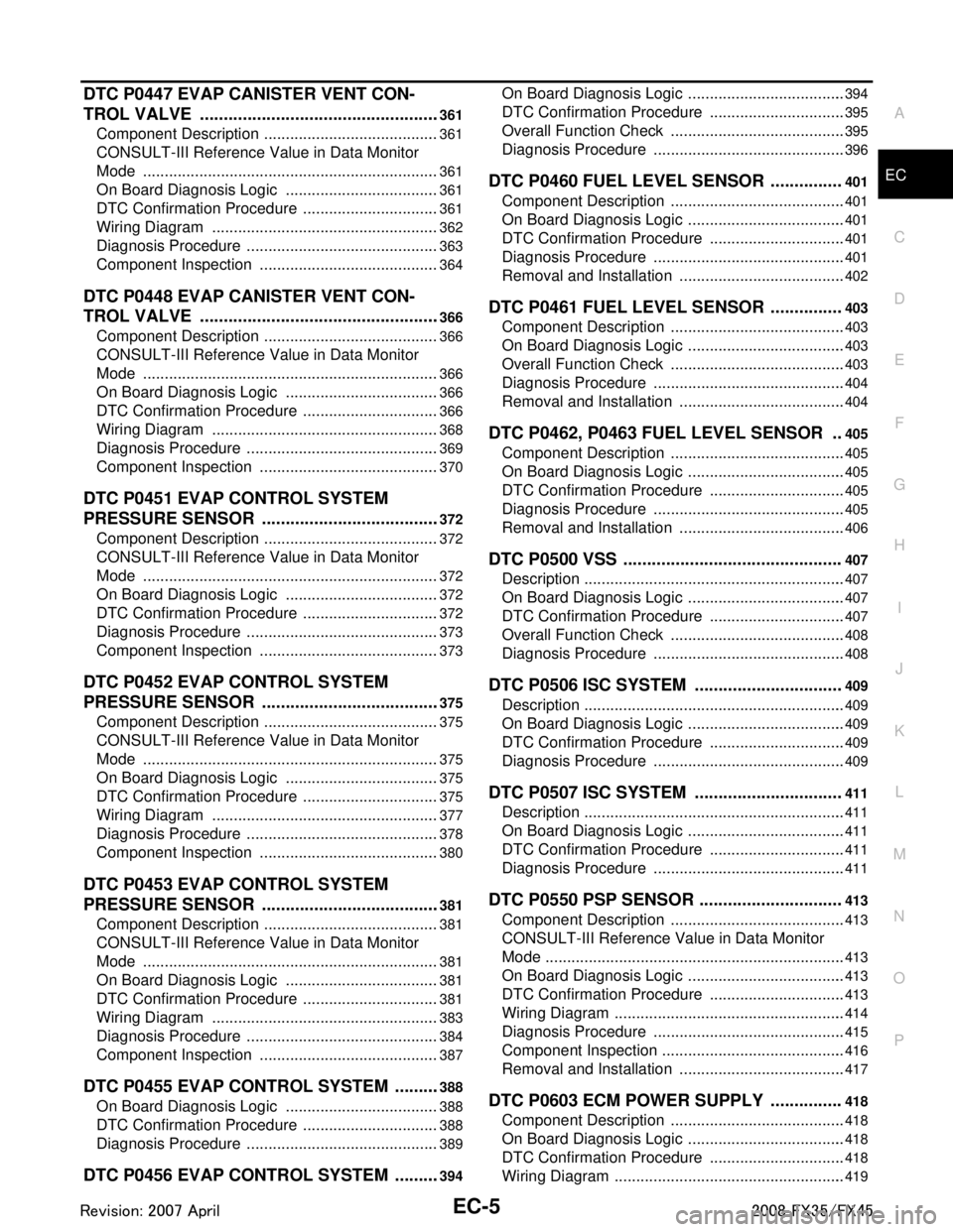
DTC P0447 EVAP CANISTER VENT CON-
TROL VALVE ................................................. ..
361
Component Description ....................................... ..361
CONSULT-III Reference Value in Data Monitor
Mode ................................................................... ..
361
On Board Diagnosis Logic ....................................361
DTC Confirmation Procedure ................................361
Wiring Diagram .....................................................362
Diagnosis Procedure .............................................363
Component Inspection ..........................................364
DTC P0448 EVAP CANISTER VENT CON-
TROL VALVE ...................................................
366
Component Description ....................................... ..366
CONSULT-III Reference Value in Data Monitor
Mode ................................................................... ..
366
On Board Diagnosis Logic ....................................366
DTC Confirmation Procedure ................................366
Wiring Diagram .....................................................368
Diagnosis Procedure .............................................369
Component Inspection ..........................................370
DTC P0451 EVAP CONTROL SYSTEM
PRESSURE SENSOR .................................... ..
372
Component Description ....................................... ..372
CONSULT-III Reference Value in Data Monitor
Mode ................................................................... ..
372
On Board Diagnosis Logic ....................................372
DTC Confirmation Procedure ................................372
Diagnosis Procedure .............................................373
Component Inspection ..........................................373
DTC P0452 EVAP CONTROL SYSTEM
PRESSURE SENSOR .................................... ..
375
Component Description ....................................... ..375
CONSULT-III Reference Value in Data Monitor
Mode ................................................................... ..
375
On Board Diagnosis Logic ....................................375
DTC Confirmation Procedure ................................375
Wiring Diagram .....................................................377
Diagnosis Procedure .............................................378
Component Inspection ..........................................380
DTC P0453 EVAP CONTROL SYSTEM
PRESSURE SENSOR .................................... ..
381
Component Description ....................................... ..381
CONSULT-III Reference Value in Data Monitor
Mode ................................................................... ..
381
On Board Diagnosis Logic ....................................381
DTC Confirmation Procedure ................................381
Wiring Diagram .....................................................383
Diagnosis Procedure .............................................384
Component Inspection ..........................................387
DTC P0455 EVAP CONTROL SYSTEM ..........388
On Board Diagnosis Logic .................................. ..388
DTC Confirmation Procedure ................................388
Diagnosis Procedure .............................................389
DTC P0456 EVAP CONTROL SYSTEM ..........394
On Board Diagnosis Logic ................................... ..394
DTC Confirmation Procedure ................................395
Overall Function Check .........................................395
Diagnosis Procedure .............................................396
DTC P0460 FUEL LEVEL SENSOR ...............401
Component Description .........................................401
On Board Diagnosis Logic .....................................401
DTC Confirmation Procedure ................................401
Diagnosis Procedure .............................................401
Removal and Installation .......................................402
DTC P0461 FUEL LEVEL SENSOR ...............403
Component Description .........................................403
On Board Diagnosis Logic .....................................403
Overall Function Check .........................................403
Diagnosis Procedure .............................................404
Removal and Installation .......................................404
DTC P0462, P0463 FUEL LEVEL SENSOR ..405
Component Description .........................................405
On Board Diagnosis Logic .....................................405
DTC Confirmation Procedure ................................405
Diagnosis Procedure .............................................405
Removal and Installation .......................................406
DTC P0500 VSS ..............................................407
Description .............................................................407
On Board Diagnosis Logic .....................................407
DTC Confirmation Procedure ................................407
Overall Function Check .........................................408
Diagnosis Procedure .............................................408
DTC P0506 ISC SYSTEM ...............................409
Description .............................................................409
On Board Diagnosis Logic .....................................409
DTC Confirmation Procedure ................................409
Diagnosis Procedure .............................................409
DTC P0507 ISC SYSTEM ...............................411
Description .............................................................411
On Board Diagnosis Logic .....................................411
DTC Confirmation Procedure ................................411
Diagnosis Procedure .............................................411
DTC P0550 PSP SENSOR ..............................413
Component Description .........................................413
CONSULT-III Reference Value in Data Monitor
Mode ......................................................................
413
On Board Diagnosis Logic .....................................413
DTC Confirmation Procedure ................................413
Wiring Diagram ......................................................414
Diagnosis Procedure .............................................415
Component Inspection ...........................................416
Removal and Installation .......................................417
DTC P0603 ECM POWER SUPPLY ...............418
Component Description .........................................418
On Board Diagnosis Logic .....................................418
DTC Confirmation Procedure ................................418
Wiring Diagram ......................................................419
3AA93ABC3ACD3AC03ACA3AC03AC63AC53A913A773A893A873A873A8E3A773A983AC73AC93AC03AC3
3A893A873A873A8F3A773A9D3AAF3A8A3A8C3A863A9D3AAF3A8B3A8C
Page 1248 of 3924

EC-8
Component Inspection ...........................................545
ASCD INDICATOR ..........................................547
Component Description ....................................... ..547
CONSULT-III Reference Value in Data Monitor
Mode .................................................................... ..
547
Wiring Diagram ......................................................548
Diagnosis Procedure .............................................548
ELECTRICAL LOAD SIGNAL .........................550
Description ........................................................... ..550
CONSULT-III Reference Value in Data Monitor
Mode .................................................................... ..
550
Diagnosis Procedure .............................................550
FUEL INJECTOR .............................................552
Component Description ....................................... ..552
CONSULT-III Reference Value in Data Monitor
Mode .................................................................... ..
552
Wiring Diagram ......................................................553
Diagnosis Procedure .............................................554
Component Inspection ...........................................557
Removal and Installation .......................................557
FUEL PUMP .....................................................558
Description ........................................................... ..558
CONSULT-III Reference Value in Data Monitor
Mode .................................................................... ..
558
Wiring Diagram ......................................................559
Diagnosis Procedure .............................................560
Component Inspection ...........................................562
Removal and Installation .......................................562
ICC BRAKE SWITCH ......................................563
Component Description ....................................... ..563
CONSULT-III Reference Value in Data Monitor
Mode .................................................................... ..
563
Wiring Diagram ......................................................564
Diagnosis Procedure .............................................565
Component Inspection ...........................................567
IGNITION SIGNAL ...........................................569
Component Description ....................................... ..569
Wiring Diagram ......................................................570
Diagnosis Procedure .............................................575
Component Inspection ...........................................578
Removal and Installation .......................................580
REFRIGERANT PRESSURE SENSOR ..........581
Component Description ....................................... ..581
Wiring Diagram ......................................................582
Diagnosis Procedure .............................................583
Removal and Installation .......................................585
SNOW MODE SWITCH ...................................586
Description ........................................................... ..586
CONSULT-III Reference Value in Data Monitor
Mode .................................................................... ..
586
Wiring Diagram ......................................................587
Diagnosis Procedure .............................................587
Component Inspection ...........................................589
MIL AND DATA LINK CONNECTOR ...............591
Wiring Diagram .................................................... .591
SERVICE DATA AND SPECIFICATIONS
(SDS) ................................................................
593
Fuel Pressure ....................................................... .593
Idle Speed and Ignition Timing .............................593
Calculated Load Value ..........................................593
Mass Air Flow Sensor ...........................................593
Intake Air Temperature Sensor .............................593
Engine Coolant Temperature Sensor ...................593
Air Fuel Ratio (A/F) Sensor 1 Heater ....................593
Heated Oxygen sensor 2 Heater ..........................593
Crankshaft Position Sensor (POS) .......................594
Camshaft Position Sensor (PHASE) .....................594
Throttle Control Motor .......................................... .594
Fuel Injector ..........................................................594
Fuel Pump .............................................................594
VK45DE
SERVICE INFORMATION .. .......................
595
INDEX FOR DTC ............................................ ..595
DTC No. Index ..................................................... .595
Alphabetical Index .................................................598
PRECAUTIONS .............................................. ..603
Precaution for Supplemental Restraint System
(SRS) "AIR BAG" and "SEAT BELT PRE-TEN-
SIONER" .............................................................. .
603
Precaution for Procedure without Cowl Top Cover .603
On Board Diagnosis (OBD) System of Engine and
A/T ........................................................................
603
Precaution .............................................................604
PREPARATION ................................................607
Special Service Tool ............................................ .607
Commercial Service Tool ......................................608
ENGINE CONTROL SYSTEM ..........................609
Schematic ............................................................ .609
Multiport Fuel Injection (MFI) System ...................609
Electronic Ignition (EI) System ..............................612
Fuel Cut Control (at No Load and High Engine
Speed) ..................................................................
612
AIR CONDITIONING CUT CONTROL .............614
Input/Output Signal Chart .................................... .614
System Description ...............................................614
AUTOMATIC SPEED CONTROL DEVICE
(ASCD) ..............................................................
615
System Description .............................................. .615
Component Description ........................................616
CAN COMMUNICATION ..................................617
System Description .............................................. .617
EVAPORATIVE EMISSION SYSTEM ..............618
Description ........................................................... .618
Component Inspection ..........................................620
3AA93ABC3ACD3AC03ACA3AC03AC63AC53A913A773A893A873A873A8E3A773A983AC73AC93AC03AC3
3A893A873A873A8F3A773A9D3AAF3A8A3A8C3A863A9D3AAF3A8B3A8C
Page 1249 of 3924

EC-9
C
DE
F
G H
I
J
K L
M
EC A
N
O P
Removal and Installation .....................................
..
622
How to Detect Fuel Vapor Leakage ......................622
ON BOARD REFUELING VAPOR RECOV-
ERY (ORVR) .....................................................
624
System Description ............................................. ..624
Diagnosis Procedure .............................................624
Component Inspection ..........................................626
POSITIVE CRANKCASE VENTILATION ........629
Description .......................................................... ..629
Component Inspection ..........................................629
IVIS (INFINITI VEHICLE IMMOBILIZER SYS-
TEM-NATS) ......................................................
631
Description .......................................................... ..631
ON BOARD DIAGNOSTIC (OBD) SYSTEM ....632
Introduction ......................................................... ..632
Two Trip Detection Logic ......................................632
Emission-related Diagnostic Information ...............633
Malfunction Indicator Lamp (MIL) ..........................649
OBD System Operation Chart ...............................652
BASIC SERVICE PROCEDURE ......................658
Basic Inspection .................................................. ..658
Idle Speed and Ignition Timing Check ..................661
Procedure After Replacing ECM ...........................662
VIN Registration ....................................................662
Accelerator Pedal Released Position Learning .....662
Throttle Valve Closed Position Learning ...............663
Idle Air Volume Learning .......................................663
Fuel Pressure Check .............................................665
TROUBLE DIAGNOSIS ...................................666
Trouble Diagnosis Introduction ........................... ..666
DTC Inspection Priority Chart ...............................670
Fail-Safe Chart ......................................................671
Symptom Matrix Chart ..........................................673
Engine Control Component Parts Location ...........677
Vacuum Hose Drawing .........................................684
Circuit Diagram .....................................................685
ECM Harness Connector Terminal Layout ...........687
ECM Terminal and Reference Value ....................687
CONSULT-III Function (ENGINE) .........................695
Generic Scan Tool (GST) Function .......................704
CONSULT-III Reference Value in Data Monitor
Mode ................................................................... ..
705
TROUBLE DIAGNOSIS - SPECIFICATION
VALUE ..............................................................
709
Description .......................................................... ..709
Testing Condition ..................................................709
Inspection Procedure ............................................709
Diagnosis Procedure .............................................710
TROUBLE DIAGNOSIS FOR INTERMITTENT
INCIDENT .........................................................
717
Description .......................................................... ..717
Diagnosis Procedure .............................................717
POWER SUPPLY AND GROUND CIRCUIT ..718
Wiring Diagram .................................................... ..718
Diagnosis Procedure .............................................719
Ground Inspection .................................................723
DTC U1000, U1001 CAN COMMUNICATION
LINE .................................................................
724
Description .............................................................724
On Board Diagnosis Logic .....................................724
DTC Confirmation Procedure ................................724
Wiring Diagram ......................................................725
Diagnosis Procedure .............................................725
DTC U1010 CAN COMMUNICATION .............726
Description .............................................................726
On Board Diagnosis Logic .....................................726
DTC Confirmation Procedure ................................726
Diagnosis Procedure .............................................726
DTC P0011, P0021 IVT CONTROL ................727
Description .............................................................727
CONSULT-III Reference Value in Data Monitor
Mode ......................................................................
728
On Board Diagnosis Logic .....................................728
DTC Confirmation Procedure ................................728
Wiring Diagram ......................................................730
Diagnosis Procedure .............................................733
Component Inspection ...........................................737
Removal and Installation .......................................738
DTC P0031, P0032, P0051, P0052 A/F SEN-
SOR 1 HEATER ..............................................
739
Description .............................................................739
CONSULT-III Reference Value in Data Monitor
Mode ......................................................................
739
On Board Diagnosis Logic .....................................739
DTC Confirmation Procedure ................................739
Wiring Diagram ......................................................740
Diagnosis Procedure .............................................743
Component Inspection ...........................................744
Removal and Installation .......................................745
DTC P0037, P0038, P0057, P0058 HO2S2
HEATER ..........................................................
746
Description .............................................................746
CONSULT-III Reference Value in Data Monitor
Mode ......................................................................
746
On Board Diagnosis Logic .....................................746
DTC Confirmation Procedure ................................746
Wiring Diagram ......................................................748
Diagnosis Procedure .............................................751
Component Inspection ...........................................752
Removal and Installation .......................................753
DTC P0075, P0081 IVT CONTROL SOLE-
NOID VALVE ...................................................
754
Component Description .........................................754
CONSULT-III Reference Value in Data Monitor
Mode ......................................................................
754
On Board Diagnosis Logic .....................................754
3AA93ABC3ACD3AC03ACA3AC03AC63AC53A913A773A893A873A873A8E3A773A983AC73AC93AC03AC3
3A893A873A873A8F3A773A9D3AAF3A8A3A8C3A863A9D3AAF3A8B3A8C
Page 1251 of 3924

EC-11
C
DE
F
G H
I
J
K L
M
EC A
N
O P
Removal and Installation .....................................
..
830
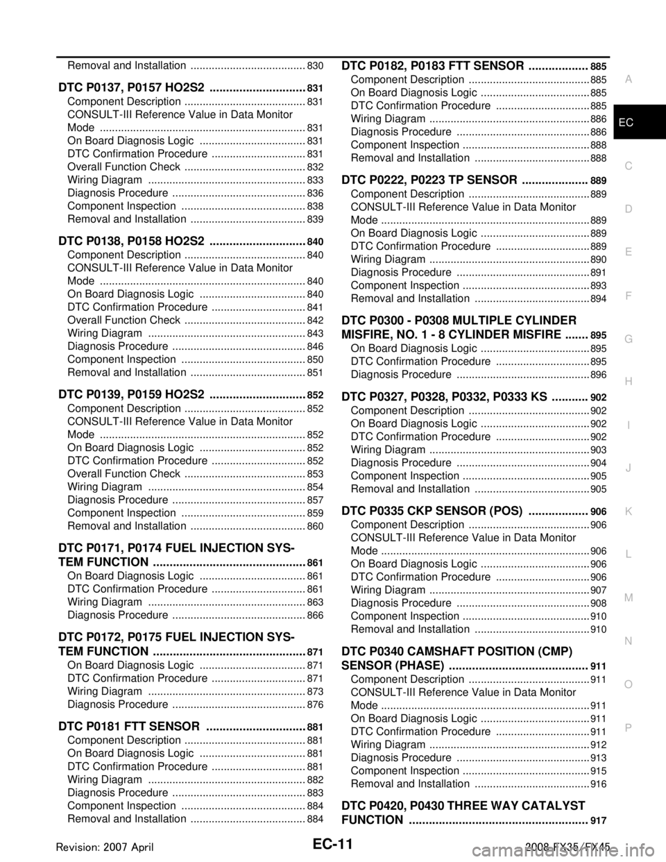
DTC P0137, P0157 HO2S2 ..............................831
Component Description ....................................... ..831
CONSULT-III Reference Value in Data Monitor
Mode ................................................................... ..
831
On Board Diagnosis Logic ....................................831
DTC Confirmation Procedure ................................831
Overall Function Check .........................................832
Wiring Diagram .....................................................833
Diagnosis Procedure .............................................836
Component Inspection ..........................................838
Removal and Installation .......................................839
DTC P0138, P0158 HO2S2 ..............................840
Component Description ....................................... ..840
CONSULT-III Reference Value in Data Monitor
Mode ................................................................... ..
840
On Board Diagnosis Logic ....................................840
DTC Confirmation Procedure ................................841
Overall Function Check .........................................842
Wiring Diagram .....................................................843
Diagnosis Procedure .............................................846
Component Inspection ..........................................850
Removal and Installation .......................................851
DTC P0139, P0159 HO2S2 ..............................852
Component Description ....................................... ..852
CONSULT-III Reference Value in Data Monitor
Mode ................................................................... ..
852
On Board Diagnosis Logic ....................................852
DTC Confirmation Procedure ................................852
Overall Function Check .........................................853
Wiring Diagram .....................................................854
Diagnosis Procedure .............................................857
Component Inspection ..........................................859
Removal and Installation .......................................860
DTC P0171, P0174 FUEL INJECTION SYS-
TEM FUNCTION ............................................. ..
861
On Board Diagnosis Logic .................................. ..861
DTC Confirmation Procedure ................................861
Wiring Diagram .....................................................863
Diagnosis Procedure .............................................866
DTC P0172, P0175 FUEL INJECTION SYS-
TEM FUNCTION ............................................. ..
871
On Board Diagnosis Logic .................................. ..871
DTC Confirmation Procedure ................................871
Wiring Diagram .....................................................873
Diagnosis Procedure .............................................876
DTC P0181 FTT SENSOR ...............................881
Component Description ....................................... ..881
On Board Diagnosis Logic ....................................881
DTC Confirmation Procedure ................................881
Wiring Diagram .....................................................882
Diagnosis Procedure .............................................883
Component Inspection ..........................................884
Removal and Installation .......................................884
DTC P0182, P0183 FTT SENSOR ..................885
Component Description ....................................... ..885
On Board Diagnosis Logic .....................................885
DTC Confirmation Procedure ................................885
Wiring Diagram ......................................................886
Diagnosis Procedure .............................................886
Component Inspection ...........................................888
Removal and Installation .......................................888
DTC P0222, P0223 TP SENSOR ....................889
Component Description .........................................889
CONSULT-III Reference Value in Data Monitor
Mode ......................................................................
889
On Board Diagnosis Logic .....................................889
DTC Confirmation Procedure ................................889
Wiring Diagram ......................................................890
Diagnosis Procedure .............................................891
Component Inspection ...........................................893
Removal and Installation .......................................894
DTC P0300 - P0308 MULTIPLE CYLINDER
MISFIRE, NO. 1 - 8 CYLINDER MISFIRE .......
895
On Board Diagnosis Logic .....................................895
DTC Confirmation Procedure ................................895
Diagnosis Procedure .............................................896
DTC P0327, P0328, P0332, P0333 KS ...........902
Component Description .........................................902
On Board Diagnosis Logic .....................................902
DTC Confirmation Procedure ................................902
Wiring Diagram ......................................................903
Diagnosis Procedure .............................................904
Component Inspection ...........................................905
Removal and Installation .......................................905
DTC P0335 CKP SENSOR (POS) ..................906
Component Description .........................................906
CONSULT-III Reference Value in Data Monitor
Mode ......................................................................
906
On Board Diagnosis Logic .....................................906
DTC Confirmation Procedure ................................906
Wiring Diagram ......................................................907
Diagnosis Procedure .............................................908
Component Inspection ...........................................910
Removal and Installation .......................................910
DTC P0340 CAMSHAFT POSITION (CMP)
SENSOR (PHASE) ..........................................
911
Component Description .........................................911
CONSULT-III Reference Value in Data Monitor
Mode ......................................................................
911
On Board Diagnosis Logic .....................................911
DTC Confirmation Procedure ................................911
Wiring Diagram ......................................................912
Diagnosis Procedure .............................................913
Component Inspection ...........................................915
Removal and Installation .......................................916
DTC P0420, P0430 THREE WAY CATALYST
FUNCTION ......................................................
917
3AA93ABC3ACD3AC03ACA3AC03AC63AC53A913A773A893A873A873A8E3A773A983AC73AC93AC03AC3
3A893A873A873A8F3A773A9D3AAF3A8A3A8C3A863A9D3AAF3A8B3A8C
Page 1252 of 3924

EC-12
On Board Diagnosis Logic .....................................917
DTC Confirmation Procedure ................................917
Overall Function Check .........................................918
Diagnosis Procedure .............................................918
DTC P0441 EVAP CONTROL SYSTEM .........921
System Description .............................................. ..921
On Board Diagnosis Logic .....................................921
DTC Confirmation Procedure ................................921
Overall Function Check .........................................922
Diagnosis Procedure .............................................922
DTC P0442 EVAP CONTROL SYSTEM .........926
On Board Diagnosis Logic ................................... ..926
DTC Confirmation Procedure ................................926
Diagnosis Procedure .............................................927
DTC P0443 EVAP CANISTER PURGE VOL-
UME CONTROL SOLENOID VALVE ..............
933
Description ........................................................... ..933
CONSULT-III Reference Value in Data Monitor
Mode .................................................................... ..
933
On Board Diagnosis Logic .....................................934
DTC Confirmation Procedure ................................934
Wiring Diagram ......................................................935
Diagnosis Procedure .............................................936
Component Inspection ...........................................939
Removal and Installation .......................................939
DTC P0444, P0445 EVAP CANISTER PURGE
VOLUME CONTROL SOLENOID VALVE ......
940
Description ........................................................... ..940
CONSULT-III Reference Value in Data Monitor
Mode .................................................................... ..
940
On Board Diagnosis Logic .....................................941
DTC Confirmation Procedure ................................941
Wiring Diagram ......................................................942
Diagnosis Procedure .............................................943
Component Inspection ...........................................945
Removal and Installation .......................................945
DTC P0447 EVAP CANISTER VENT CON-
TROL VALVE ...................................................
946
Component Description ....................................... ..946
CONSULT-III Reference Value in Data Monitor
Mode .................................................................... ..
946
On Board Diagnosis Logic .....................................946
DTC Confirmation Procedure ................................946
Wiring Diagram ......................................................947
Diagnosis Procedure .............................................948
Component Inspection ...........................................949
DTC P0448 EVAP CANISTER VENT CON-
TROL VALVE ...................................................
951
Component Description ....................................... ..951
CONSULT-III Reference Value in Data Monitor
Mode .................................................................... ..
951
On Board Diagnosis Logic .....................................951
DTC Confirmation Procedure ................................951
Wiring Diagram ......................................................953
Diagnosis Procedure ............................................ .954
Component Inspection ..........................................955
DTC P0451 EVAP CONTROL SYSTEM
PRESSURE SENSOR .................................... ..
957
Component Description ....................................... .957
CONSULT-III Reference Value in Data Monitor
Mode .....................................................................
957
On Board Diagnosis Logic ....................................957
DTC Confirmation Procedure ................................957
Diagnosis Procedure .............................................958
Component Inspection ..........................................958
DTC P0452 EVAP CONTROL SYSTEM
PRESSURE SENSOR .................................... ..
960
Component Description ....................................... .960
CONSULT-III Reference Value in Data Monitor
Mode .....................................................................
960
On Board Diagnosis Logic ....................................960
DTC Confirmation Procedure ................................960
Wiring Diagram .....................................................962
Diagnosis Procedure .............................................963
Component Inspection ..........................................965
DTC P0453 EVAP CONTROL SYSTEM
PRESSURE SENSOR .................................... ..
966
Component Description ....................................... .966
CONSULT-III Reference Value in Data Monitor
Mode .....................................................................
966
On Board Diagnosis Logic ....................................966
DTC Confirmation Procedure ................................966
Wiring Diagram .....................................................968
Diagnosis Procedure .............................................969
Component Inspection ..........................................972
DTC P0455 EVAP CONTROL SYSTEM ..........973
On Board Diagnosis Logic ................................... .973
DTC Confirmation Procedure ................................973
Diagnosis Procedure .............................................974
DTC P0456 EVAP CONTROL SYSTEM ..........979
On Board Diagnosis Logic ................................... .979
DTC Confirmation Procedure ................................980
Overall Function Check .........................................980
Diagnosis Procedure .............................................981
DTC P0460 FUEL LEVEL SENSOR ................986
Component Description ....................................... .986
On Board Diagnosis Logic ....................................986
DTC Confirmation Procedure ................................986
Diagnosis Procedure .............................................986
Removal and Installation .......................................987
DTC P0461 FUEL LEVEL SENSOR ................988
Component Description ....................................... .988
On Board Diagnosis Logic ....................................988
Overall Function Check .........................................988
Diagnosis Procedure .............................................989
Removal and Installation .......................................989
3AA93ABC3ACD3AC03ACA3AC03AC63AC53A913A773A893A873A873A8E3A773A983AC73AC93AC03AC3
3A893A873A873A8F3A773A9D3AAF3A8A3A8C3A863A9D3AAF3A8B3A8C
Page 1253 of 3924

EC-13
C
DE
F
G H
I
J
K L
M
EC A
N
O P
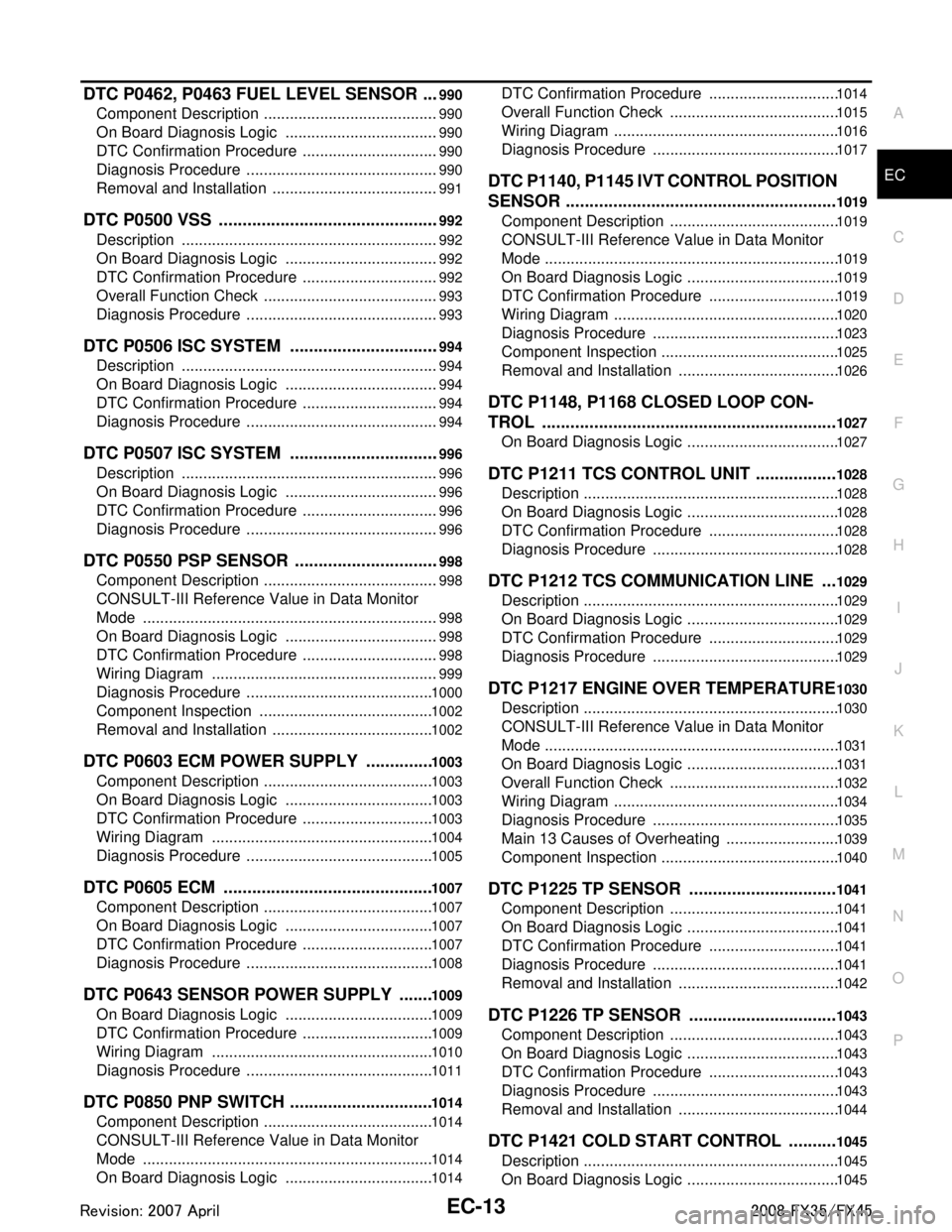
DTC P0462, P0463 FUEL LEVEL SENSOR .. ..990
Component Description ....................................... ..990
On Board Diagnosis Logic ....................................990
DTC Confirmation Procedure ................................990
Diagnosis Procedure .............................................990
Removal and Installation .......................................991
DTC P0500 VSS ...............................................992
Description .......................................................... ..992
On Board Diagnosis Logic ....................................992
DTC Confirmation Procedure ................................992
Overall Function Check .........................................993
Diagnosis Procedure .............................................993
DTC P0506 ISC SYSTEM ................................994
Description .......................................................... ..994
On Board Diagnosis Logic ....................................994
DTC Confirmation Procedure ................................994
Diagnosis Procedure .............................................994
DTC P0507 ISC SYSTEM ................................996
Description .......................................................... ..996
On Board Diagnosis Logic ....................................996
DTC Confirmation Procedure ................................996
Diagnosis Procedure .............................................996
DTC P0550 PSP SENSOR ............................. ..998
Component Description ....................................... ..998
CONSULT-III Reference Value in Data Monitor
Mode ................................................................... ..
998
On Board Diagnosis Logic ....................................998
DTC Confirmation Procedure ................................998
Wiring Diagram .....................................................999
Diagnosis Procedure ...........................................1000
Component Inspection ........................................1002
Removal and Installation .....................................1002
DTC P0603 ECM POWER SUPPLY ..............1003
Component Description .......................................1003
On Board Diagnosis Logic ..................................1003
DTC Confirmation Procedure ..............................1003
Wiring Diagram ...................................................1004
Diagnosis Procedure ...........................................1005
DTC P0605 ECM ............................................1007
Component Description .......................................1007
On Board Diagnosis Logic ..................................1007
DTC Confirmation Procedure ..............................1007
Diagnosis Procedure ...........................................1008
DTC P0643 SENSOR POWER SUPPLY .......1009
On Board Diagnosis Logic ..................................1009
DTC Confirmation Procedure ..............................1009
Wiring Diagram ...................................................1010
Diagnosis Procedure ...........................................1011
DTC P0850 PNP SWITCH ..............................1014
Component Description .......................................1014
CONSULT-III Reference Value in Data Monitor
Mode ...................................................................
1014
On Board Diagnosis Logic ..................................1014
DTC Confirmation Procedure ..............................1014
Overall Function Check .......................................1015
Wiring Diagram ....................................................1016
Diagnosis Procedure ...........................................1017
DTC P1140, P1145 IVT CONTROL POSITION
SENSOR .........................................................
1019
Component Description .......................................1019
CONSULT-III Reference Value in Data Monitor
Mode ....................................................................
1019
On Board Diagnosis Logic ...................................1019
DTC Confirmation Procedure ..............................1019
Wiring Diagram ....................................................1020
Diagnosis Procedure ...........................................1023
Component Inspection .........................................1025
Removal and Installation .....................................1026
DTC P1148, P1168 CLOSED LOOP CON-
TROL ..............................................................
1027
On Board Diagnosis Logic ...................................1027
DTC P1211 TCS CONTROL UNIT .................1028
Description ...........................................................1028
On Board Diagnosis Logic ...................................1028
DTC Confirmation Procedure ..............................1028
Diagnosis Procedure ...........................................1028
DTC P1212 TCS COMMUNICATION LINE ...1029
Description ...........................................................1029
On Board Diagnosis Logic ...................................1029
DTC Confirmation Procedure ..............................1029
Diagnosis Procedure ...........................................1029
DTC P1217 ENGINE OVER TEMPERATURE 1030
Description ...........................................................1030
CONSULT-III Reference Value in Data Monitor
Mode ....................................................................
1031
On Board Diagnosis Logic ...................................1031
Overall Function Check .......................................1032
Wiring Diagram ....................................................1034
Diagnosis Procedure ...........................................1035
Main 13 Causes of Overheating ..........................1039
Component Inspection .........................................1040
DTC P1225 TP SENSOR ...............................1041
Component Description .......................................1041
On Board Diagnosis Logic ...................................1041
DTC Confirmation Procedure ..............................1041
Diagnosis Procedure ...........................................1041
Removal and Installation .....................................1042
DTC P1226 TP SENSOR ...............................1043
Component Description .......................................1043
On Board Diagnosis Logic ...................................1043
DTC Confirmation Procedure ..............................1043
Diagnosis Procedure ...........................................1043
Removal and Installation .....................................1044
DTC P1421 COLD START CONTROL ..........1045
Description ...........................................................1045
On Board Diagnosis Logic ...................................1045
3AA93ABC3ACD3AC03ACA3AC03AC63AC53A913A773A893A873A873A8E3A773A983AC73AC93AC03AC3
3A893A873A873A8F3A773A9D3AAF3A8A3A8C3A863A9D3AAF3A8B3A8C
Page 1255 of 3924

EC-15
C
DE
F
G H
I
J
K L
M
EC A
N
O P
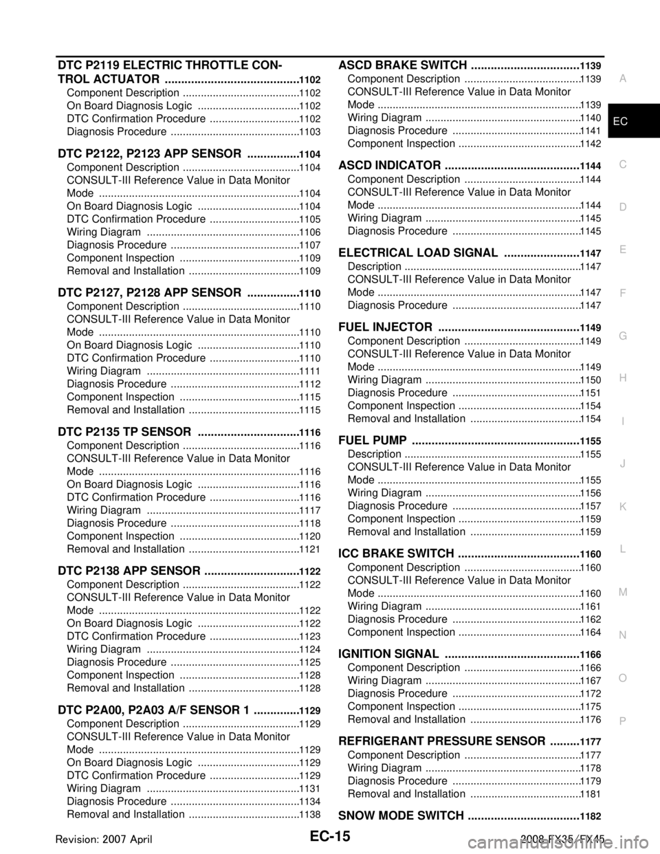
DTC P2119 ELECTRIC THROTTLE CON-
TROL ACTUATOR .........................................
1102
Component Description .......................................1102
On Board Diagnosis Logic ..................................1102
DTC Confirmation Procedure ..............................1102
Diagnosis Procedure ...........................................1103
DTC P2122, P2123 APP SENSOR ................1104
Component Description .......................................1104
CONSULT-III Refe rence Value in Data Monitor
Mode ...................................................................
1104
On Board Diagnosis Logic ..................................1104
DTC Confirmation Procedure ..............................1105
Wiring Diagram ...................................................1106
Diagnosis Procedure ...........................................1107
Component Inspection ........................................1109
Removal and Installation .....................................1109
DTC P2127, P2128 APP SENSOR ................1110
Component Description .......................................1110
CONSULT-III Refe rence Value in Data Monitor
Mode ...................................................................
1110
On Board Diagnosis Logic ..................................1110
DTC Confirmation Procedure ..............................1110
Wiring Diagram ...................................................1111
Diagnosis Procedure ...........................................1112
Component Inspection ........................................1115
Removal and Installation .....................................1115
DTC P2135 TP SENSOR ...............................1116
Component Description .......................................1116
CONSULT-III Refe rence Value in Data Monitor
Mode ...................................................................
1116
On Board Diagnosis Logic ..................................1116
DTC Confirmation Procedure ..............................1116
Wiring Diagram ...................................................1117
Diagnosis Procedure ...........................................1118
Component Inspection ........................................1120
Removal and Installation .....................................1121
DTC P2138 APP SENSOR .............................1122
Component Description .......................................1122
CONSULT-III Refe rence Value in Data Monitor
Mode ...................................................................
1122
On Board Diagnosis Logic ..................................1122
DTC Confirmation Procedure ..............................1123
Wiring Diagram ...................................................1124
Diagnosis Procedure ...........................................1125
Component Inspection ........................................1128
Removal and Installation .....................................1128
DTC P2A00, P2A03 A/F SENSOR 1 ..............1129
Component Description .......................................1129
CONSULT-III Refe rence Value in Data Monitor
Mode ...................................................................
1129
On Board Diagnosis Logic ..................................1129
DTC Confirmation Procedure ..............................1129
Wiring Diagram ...................................................1131
Diagnosis Procedure ...........................................1134
Removal and Installation .....................................1138
ASCD BRAKE SWITCH .................................1139
Component Description .......................................1139
CONSULT-III Reference Value in Data Monitor
Mode ....................................................................
1139
Wiring Diagram ....................................................1140
Diagnosis Procedure ...........................................1141
Component Inspection .........................................1142
ASCD INDICATOR .........................................1144
Component Description .......................................1144
CONSULT-III Reference Value in Data Monitor
Mode ....................................................................
1144
Wiring Diagram ....................................................1145
Diagnosis Procedure ...........................................1145
ELECTRICAL LOAD SIGNAL .......................1147
Description ...........................................................1147
CONSULT-III Reference Value in Data Monitor
Mode ....................................................................
1147
Diagnosis Procedure ...........................................1147
FUEL INJECTOR ...........................................1149
Component Description .......................................1149
CONSULT-III Reference Value in Data Monitor
Mode ....................................................................
1149
Wiring Diagram ....................................................1150
Diagnosis Procedure ...........................................1151
Component Inspection .........................................1154
Removal and Installation .....................................1154
FUEL PUMP ...................................................1155
Description ...........................................................1155
CONSULT-III Reference Value in Data Monitor
Mode ....................................................................
1155
Wiring Diagram ....................................................1156
Diagnosis Procedure ...........................................1157
Component Inspection .........................................1159
Removal and Installation .....................................1159
ICC BRAKE SWITCH .....................................1160
Component Description .......................................1160
CONSULT-III Reference Value in Data Monitor
Mode ....................................................................
1160
Wiring Diagram ....................................................1161
Diagnosis Procedure ...........................................1162
Component Inspection .........................................1164
IGNITION SIGNAL .........................................1166
Component Description .......................................1166
Wiring Diagram ....................................................1167
Diagnosis Procedure ...........................................1172
Component Inspection .........................................1175
Removal and Installation .....................................1176
REFRIGERANT PRESSURE SENSOR .........1177
Component Description .......................................1177
Wiring Diagram ....................................................1178
Diagnosis Procedure ...........................................1179
Removal and Installation .....................................1181
SNOW MODE SWITCH ..................................1182
3AA93ABC3ACD3AC03ACA3AC03AC63AC53A913A773A893A873A873A8E3A773A983AC73AC93AC03AC3
3A893A873A873A8F3A773A9D3AAF3A8A3A8C3A863A9D3AAF3A8B3A8C