2008 INFINITI FX35 fuel
[x] Cancel search: fuelPage 1146 of 3924

DI-20
< SERVICE INFORMATION >
COMBINATION METERS
OK >> GO TO 2.
NG >> Replace combination meter.
2.CHECK FUEL LEVEL SENSOR (SUB) CIRCUIT
1. Turn ignition switch OFF.
2. Disconnect unified meter and A/C amp. connector and fuel level sensor unit (sub) connector.
3. Check continuity between unified meter and A/C amp. harness
connector (A) M56 terminal 28 and fuel level sensor unit (sub)
harness connector (B) B40 terminal 1.
4. Check continuity between unified meter and A/C amp. harness connector (A) M56 terminal 28 and ground.
OK or NG
OK >> GO TO 3.
NG >> Repair harness or connector.
3.CHECK FUEL LEVEL SENSOR (MAIN·SUB) CIRCUIT
1. Disconnect fuel level sensor unit and fuel pump (main) connector.
2. Check continuity between fuel level sensor unit (sub) harness
connector (A) B40 terminal 2 and fuel level sensor unit and fuel
pump (main) harness connector (B) B39 terminal 2.
3. Check continuity between fuel level sensor unit (sub) harness
connector (A) B40 terminal 2 and ground.
OK or NG
OK >> GO TO 4.
NG >> Repair harness or connector.
4.CHECK FUEL LEVEL SENSOR (MAIN) CIRCUIT
1. Check continuity between fuel level sensor unit and fuel pump (main) harness connector (A) B39 terminal 5 and unified meter
and A/C amp. harness connector (B) M56 terminal 36.
2. Check continuity between fuel level sensor unit and fuel pump (main) harness connector (A) B39 terminal 5 and ground.
OK or NG
OK >> GO TO 5.
NG >> Repair harness or connector.
5.CHECK FUEL LEVEL SENSOR
Check components. Refer to DI-21, "
Electrical Component Inspection".
OK or NG
OK >> Check fuel level sensor unit installation, and c heck whether the float arm interferes or binds with
any of the internal components in the fuel tank. Repair or replace malfunctioning part, if neces-
sary.
NG >> Replace fuel level sensor unit. 28 – 1 : Continuity should exist.
28 – Ground : Continuity should not exist.
SKIB8527E
2 – 2 : Continuity should exist.
2 – Ground : Continuity should not exist.
SKIB8697E
5 – 36 : Continuity should exist.
5 – Ground : Continuity should not exist.
SKIB8528E
3AA93ABC3ACD3AC03ACA3AC03AC63AC53A913A773A893A873A873A8E3A773A983AC73AC93AC03AC3
3A893A873A873A8F3A773A9D3AAF3A8A3A8C3A863A9D3AAF3A8B3A8C
Page 1147 of 3924
COMBINATION METERSDI-21
< SERVICE INFORMATION >
C
DE
F
G H
I
J
L
M A
B
DI
N
O P
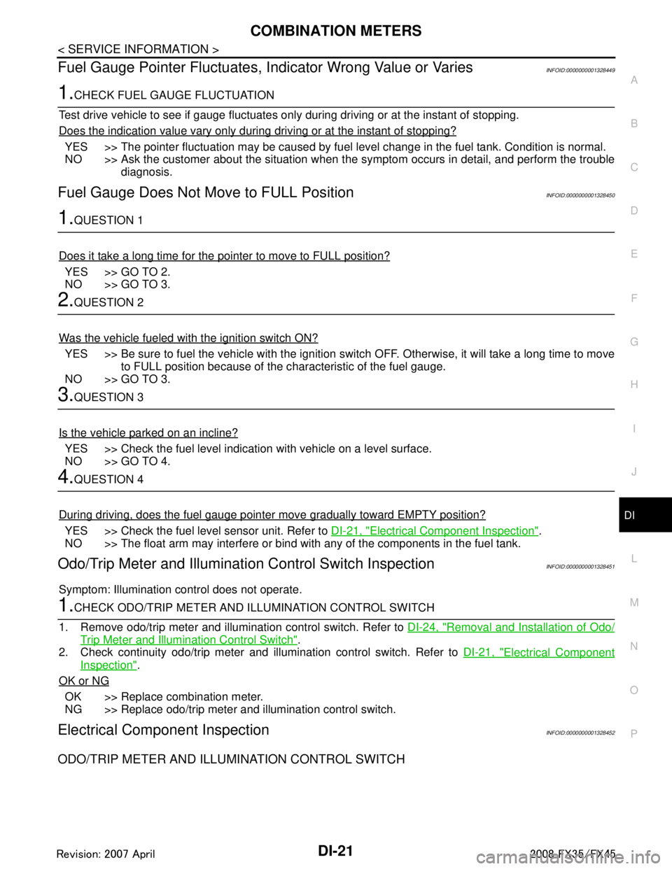
Fuel Gauge Pointer Fluctuates, Indicator Wrong Value or VariesINFOID:0000000001328449
1.CHECK FUEL GAUGE FLUCTUATION
Test drive vehicle to see if gauge fluctuates onl y during driving or at the instant of stopping.
Does the indication value vary only during driving or at the instant of stopping?
YES >> The pointer fluctuation may be caused by fuel level change in the fuel tank. Condition is normal.
NO >> Ask the customer about the situation when the symptom occurs in detail, and perform the trouble
diagnosis.
Fuel Gauge Does Not Move to FULL PositionINFOID:0000000001328450
1.QUESTION 1
Does it take a long time for the pointer to move to FULL position?
YES >> GO TO 2.
NO >> GO TO 3.
2.QUESTION 2
Was the vehicle fueled with the ignition switch ON?
YES >> Be sure to fuel the vehicle with the ignition swit ch OFF. Otherwise, it will take a long time to move
to FULL position because of the c haracteristic of the fuel gauge.
NO >> GO TO 3.
3.QUESTION 3
Is the vehicle parked on an incline?
YES >> Check the fuel level indication with vehicle on a level surface.
NO >> GO TO 4.
4.QUESTION 4
During driving, does the fuel gauge pointer move gradually toward EMPTY position?
YES >> Check the fuel level sensor unit. Refer to DI-21, "Electrical Component Inspection".
NO >> The float arm may interfere or bind with any of the components in the fuel tank.
Odo/Trip Meter and Illuminati on Control Switch InspectionINFOID:0000000001328451
Symptom: Illumination control does not operate.
1.CHECK ODO/TRIP METER AND I LLUMINATION CONTROL SWITCH
1. Remove odo/trip meter and illumination control switch. Refer to DI-24, "
Removal and Installation of Odo/
Trip Meter and Illumination Control Switch".
2. Check continuity odo/trip meter and illumination control switch. Refer to DI-21, "
Electrical Component
Inspection".
OK or NG
OK >> Replace combination meter.
NG >> Replace odo/trip meter and illumination control switch.
Electrical Component InspectionINFOID:0000000001328452
ODO/TRIP METER AND ILLUMINATION CONTROL SWITCH
3AA93ABC3ACD3AC03ACA3AC03AC63AC53A913A773A893A873A873A8E3A773A983AC73AC93AC03AC3
3A893A873A873A8F3A773A9D3AAF3A8A3A8C3A863A9D3AAF3A8B3A8C
Page 1148 of 3924
DI-22
< SERVICE INFORMATION >
COMBINATION METERS
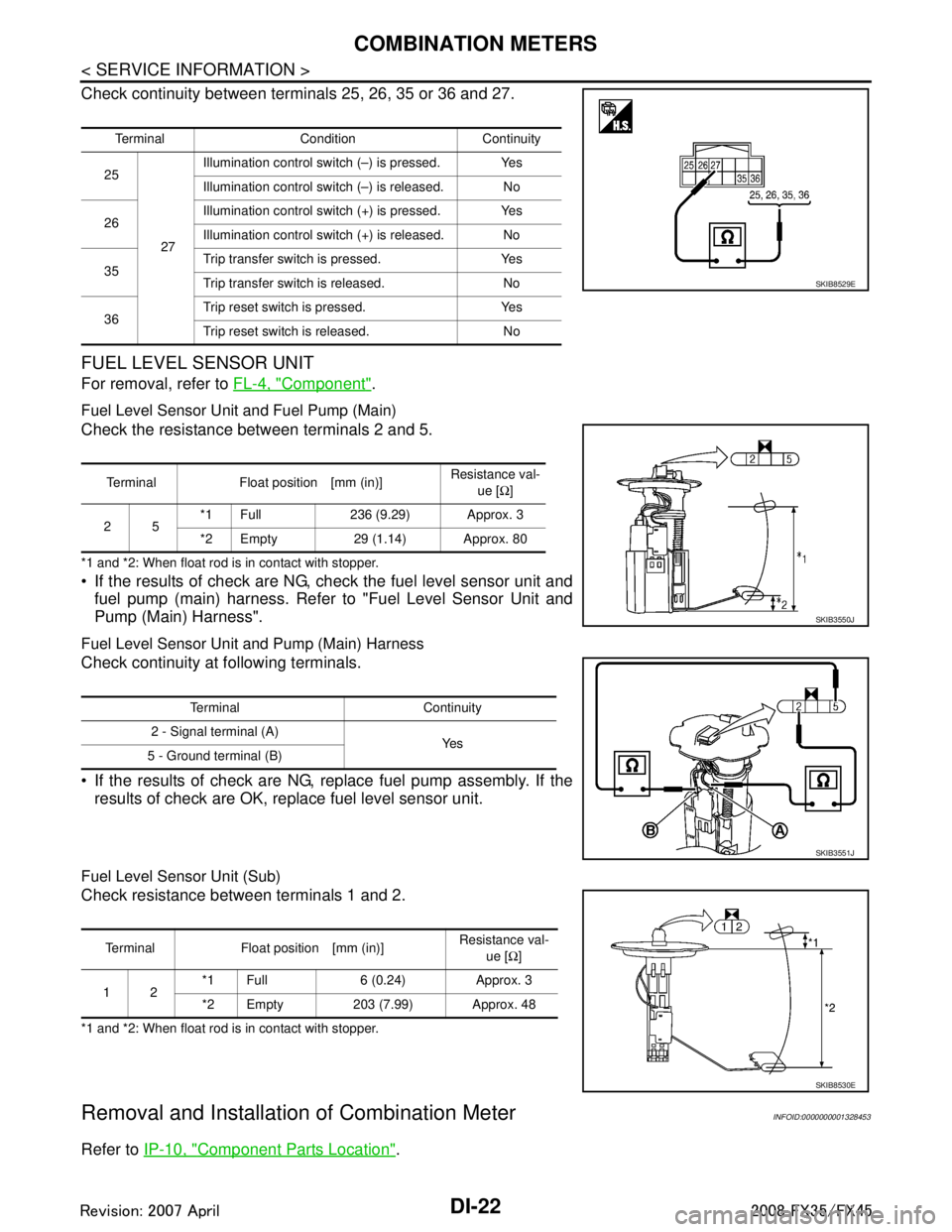
Check continuity between terminals 25, 26, 35 or 36 and 27.
FUEL LEVEL SENSOR UNIT
For removal, refer to FL-4, "Component".
Fuel Level Sensor Unit and Fuel Pump (Main)
Check the resistance between terminals 2 and 5.
*1 and *2: When float rod is in contact with stopper.
If the results of check are NG, check the fuel level sensor unit and
fuel pump (main) harness. Refer to "Fuel Level Sensor Unit and
Pump (Main) Harness".
Fuel Level Sensor Unit and Pump (Main) Harness
Check continuity at following terminals.
If the results of check are NG, replace fuel pump assembly. If the results of check are OK, replace fuel level sensor unit.
Fuel Level Sensor Unit (Sub)
Check resistance between terminals 1 and 2.
*1 and *2: When float rod is in contact with stopper.
Removal and Installation of Combination MeterINFOID:0000000001328453
Refer to IP-10, "Component Parts Location".
Terminal Condition Continuity
25
27Illumination control swit
ch (–) is pressed. Yes
Illumination control swit ch (–) is released. No
26 Illumination control swit
ch (+) is pressed. Yes
Illumination control swit ch (+) is released. No
35 Trip transfer switch is pressed. Yes
Trip transfer switch is released. No
36 Trip reset switch is pressed. Yes
Trip reset switch is released. No
SKIB8529E
Terminal Float position [mm (in)]
Resistance val-
ue [Ω]
25 *1 Full 236 (9.29) Approx. 3
*2 Empty 29 (1.14) Approx. 80
SKIB3550J
Terminal Continuity
2 - Signal terminal (A) Ye s
5 - Ground terminal (B)
SKIB3551J
Terminal Float position [mm (in)] Resistance val-
ue [Ω]
12 *1 Full 6 (0.24) Approx. 3
*2 Empty 203 (7.99) Approx. 48
SKIB8530E
3AA93ABC3ACD3AC03ACA3AC03AC63AC53A913A773A893A873A873A8E3A773A983AC73AC93AC03AC3
3A893A873A873A8F3A773A9D3AAF3A8A3A8C3A863A9D3AAF3A8B3A8C
Page 1152 of 3924
DI-26
< SERVICE INFORMATION >
UNIFIED METER AND A/C AMP
UNIFIED METER AND A/C AMP
System DescriptionINFOID:0000000001328456
For the unified meter and A/C amp., the signal required for controlling the combination meter are integrated
in the A/C auto amp.
The unified meter and A/C amp. corresponds to a CONS ULT-III function (self-diagnosis results, CAN diag-
nosis support monitor, data monitor).
COMBINATION METER CONTROL FUNCTION
Unified meter and A/C amp. receives necessary information for combination meter from each unit by CAN communication.
Unified meter and A/C amp. transmits a signals with communication line (TX, RX) between unified meter and A/C amp. and combination meter.
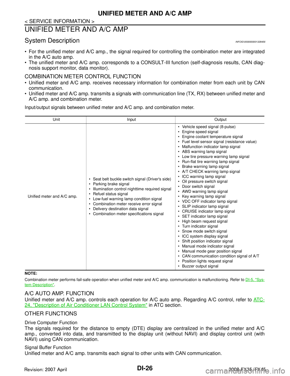
Input/output signals between unified meter and A/C amp. and combination meter.
NOTE:
Combination meter performs fail-safe operation when unified meter and A/C amp. communication is malfunctioning. Refer to DI-5, "
Sys-
tem Description".
A/C AUTO AMP. FUNCTION
Unified meter and A/C amp. controls each operation for A/C auto amp. Regarding A/C control, refer to AT C -
24, "Description of Air Conditioner LAN Control System" in ATC section.
OTHER FUNCTIONS
Drive Computer Function
The signals required for the distance to empty (DTE) display are centralized in the unified meter and A/C
amp., converted into data, and transmitted to the disp lay unit (without NAVI) and display control unit (with
NAVI) using CAN communication.
Signal Buffer Function
Unified meter and A/C amp. transmits each signal to other units with CAN communication.
Unit Input Output
Unified meter and A/C amp. Seat belt buckle switch signal (Driver's side)
Parking brake signal
Illumination control nighttime required signal
Refuel status signal
Low-fuel warning lamp condition signal
Combination meter receive error signal
Delivery destination data signal
Combination meter specifications signal Vehicle speed signal (8-pulse)
Engine speed signal
Engine coolant temperature signal
Fuel level sensor signal (resistance value)
Malfunction indicator lamp signal
ABS warning lamp signal
Low tire pressure warning lamp signal
Run-flat tire wa
rning lamp signal
Brake warning lamp signal
A/T CHECK warning lamp signal
ICC warning lamp signal
Oil pressure switch signal
Door switch signal
AWD warning lamp signal
Key warning lamp signal
VDC OFF indicator lamp signal
SLIP indicator lamp signal
CRUISE indicator lamp signal
SET indicator lamp signal
High beam request signal
Turn indicator signal
Snow mode switch signal
ICC system display signal
Shift position indicator signal
Manual mode indicator signal
Manual mode gear position signal
CAN communication condition signal of A/T
Position lights request signal
Buzzer output signal
3AA93ABC3ACD3AC03ACA3AC03AC63AC53A913A773A893A873A873A8E3A773A983AC73AC93AC03AC3
3A893A873A873A8F3A773A9D3AAF3A8A3A8C3A863A9D3AAF3A8B3A8C
Page 1154 of 3924
DI-28
< SERVICE INFORMATION >
UNIFIED METER AND A/C AMP
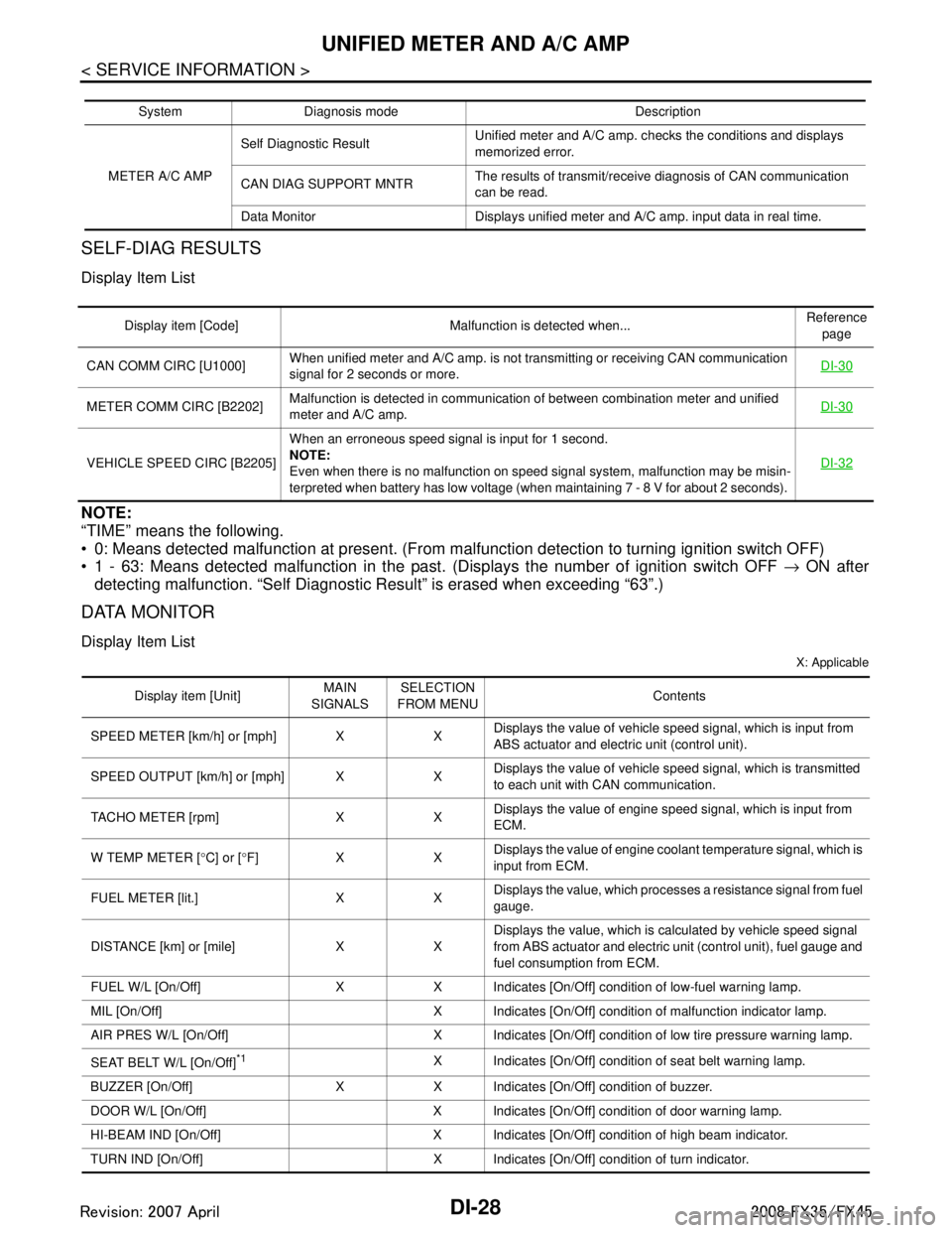
SELF-DIAG RESULTS
Display Item List
NOTE:
“TIME” means the following.
0: Means detected malfunction at present. (From malfunction detection to turning ignition switch OFF)
1 - 63: Means detected malfunction in the past . (Displays the number of ignition switch OFF → ON after
detecting malfunction. “Self Diagnostic Result” is erased when exceeding “63”.)
DATA MONITOR
Display Item List
X: Applicable
System Diagnosis mode Description
METER A/C AMP Self Diagnostic Result
Unified meter and A/C amp. checks the conditions and displays
memorized error.
CAN DIAG SUPPORT MNTR The results of transmit/receive diagnosis of CAN communication
can be read.
Data Monitor Displays unified meter and A/C amp. input data in real time.
Display item [Code] Malfunction is detected when... Reference
page
CAN COMM CIRC [U1000] When unified meter and A/C amp. is not transmitting or receiving CAN communication
signal for 2 seconds or more. DI-30
METER COMM CIRC [B2202]Malfunction is detected in communication of between combination meter and unified
meter and A/C amp.
DI-30
VEHICLE SPEED CIRC [B2205]When an erroneous speed signal is input for 1 second.
NOTE:
Even when there is no malfunction on speed signal system, malfunction may be misin-
terpreted when battery has low voltage (when maintaining 7 - 8 V for about 2 seconds). DI-32
Display item [Unit]
MAIN
SIGNALS SELECTION
FROM MENU Contents
SPEED METER [km/h] or [mph] X X Displays the value of vehicle speed signal, which is input from
ABS actuator and electric unit (control unit).
SPEED OUTPUT [km/h] or [mph] X X Displays the value of vehicle speed signal, which is transmitted
to each unit with CAN communication.
TACHO METER [rpm] X X Displays the value of engine speed signal, which is input from
ECM.
W TEMP METER [ °C] or [ °F] X X Displays the value of engine coolant temperature signal, which is
input from ECM.
FUEL METER [lit.] X X Displays the value, which processes a resistance signal from fuel
gauge.
DISTANCE [km] or [mile] X X Displays the value, which is calculated by vehicle speed signal
from ABS actuator and electric unit
(control unit), fuel gauge and
fuel consumption from ECM.
FUEL W/L [On/Off] X X Indicates [On/Off] condition of low-fuel warning lamp.
MIL [On/Off] X Indicates [On/Off] condition of malfunction indicator lamp.
AIR PRES W/L [On/Off] X Indicates [On/Off] condition of low tire pressure warning lamp.
SEAT BELT W/L [On/Off]
*1X Indicates [On/Off] condition of seat belt warning lamp.
BUZZER [On/Off] X X Indicates [On/Off] condition of buzzer.
DOOR W/L [On/Off] X Indicates [On/Off] condition of door warning lamp.
HI-BEAM IND [On/Off] X Indicates [On/Off] condition of high beam indicator.
TURN IND [On/Off] X Indicates [On/Off] condition of turn indicator.
3AA93ABC3ACD3AC03ACA3AC03AC63AC53A913A773A893A873A873A8E3A773A983AC73AC93AC03AC3
3A893A873A873A8F3A773A9D3AAF3A8A3A8C3A863A9D3AAF3A8B3A8C
Page 1197 of 3924
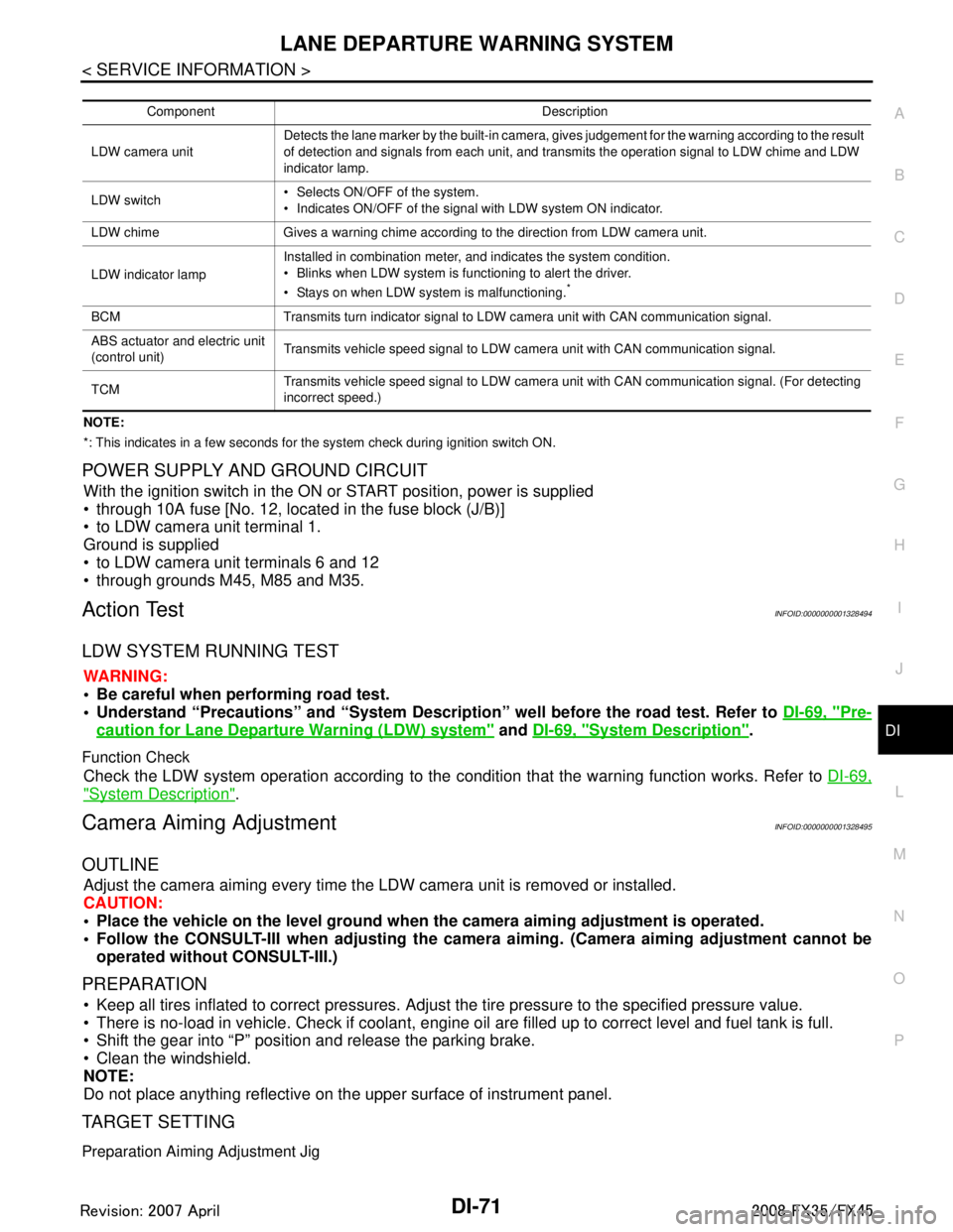
LANE DEPARTURE WARNING SYSTEMDI-71
< SERVICE INFORMATION >
C
DE
F
G H
I
J
L
M A
B
DI
N
O P
NOTE:
*: This indicates in a few seconds for the system check during ignition switch ON.
POWER SUPPLY AND GROUND CIRCUIT
With the ignition switch in the ON or START position, power is supplied
through 10A fuse [No. 12, located in the fuse block (J/B)]
to LDW camera unit terminal 1.
Ground is supplied
to LDW camera unit terminals 6 and 12
through grounds M45, M85 and M35.
Action TestINFOID:0000000001328494
LDW SYSTEM RUNNING TEST
WARNING:
Be careful when performing road test.
Understand “Precautions” and “System Description” well before the road test. Refer to DI-69, "
Pre-
caution for Lane Departure Warning (LDW) system" and DI-69, "System Description".
Function Check
Check the LDW system operation according to the c ondition that the warning function works. Refer to DI-69,
"System Description".
Camera Aiming AdjustmentINFOID:0000000001328495
OUTLINE
Adjust the camera aiming every time the LDW camera unit is removed or installed.
CAUTION:
Place the vehicle on the level ground when the camera aiming adjustment is operated.
Follow the CONSULT-III when ad justing the camera aiming. (Camera aiming adjustment cannot be
operated without CONSULT-III.)
PREPARATION
Keep all tires inflated to correct pressures. Adjust the tire pressure to the specified pressure value.
There is no-load in vehicle. Check if coolant, engine oil are filled up to correct level and fuel tank is full.
Shift the gear into “P” position and release the parking brake.
Clean the windshield.
NOTE:
Do not place anything reflective on t he upper surface of instrument panel.
TARGET SETTING
Preparation Aiming Adjustment Jig
Component Description
LDW camera unit Detects the lane marker by the built-in camera, gives judgement for the warning according to the result
of detection and signals from each unit, and transmits the operation signal to LDW chime and LDW
indicator lamp.
LDW switch Selects ON/OFF of the system.
Indicates ON/OFF of the signal with LDW system ON indicator.
LDW chime Gives a warning chime according to the direction from LDW camera unit.
LDW indicator lamp Installed in combination meter, and indicates the system condition.
Blinks when LDW system is functioning to alert the driver.
Stays on when LDW system is malfunctioning.
*
BCM Transmits turn indicator signal to LDW camera unit with CAN communication signal.
ABS actuator and electric unit
(control unit)
Transmits vehicle speed signal to LDW camera unit with CAN communication signal.
TCM Transmits vehicle speed signal to LDW camera unit with CAN communication signal. (For detecting
incorrect speed.)
3AA93ABC3ACD3AC03ACA3AC03AC63AC53A913A773A893A873A873A8E3A773A983AC73AC93AC03AC3
3A893A873A873A8F3A773A9D3AAF3A8A3A8C3A863A9D3AAF3A8B3A8C
Page 1241 of 3924
EC-1
ENGINE
C
DE
F
G H
I
J
K L
M
SECTION EC
A
EC
N
O P
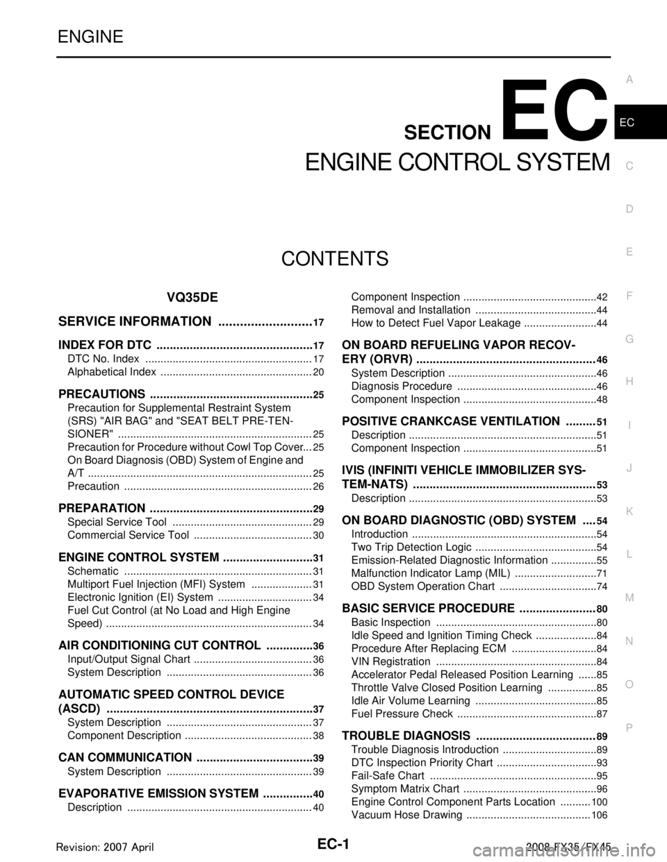
CONTENTS
ENGINE CONTROL SYSTEM
VQ35DE
SERVICE INFORMATION .. .........................
17
INDEX FOR DTC ............................................ ....17
DTC No. Index .................................................... ....17
Alphabetical Index ...................................................20
PRECAUTIONS ..................................................25
Precaution for Supplemental Restraint System
(SRS) "AIR BAG" and "SEAT BELT PRE-TEN-
SIONER" ............................................................. ....
25
Precaution for Procedure without Cowl Top Cover ....25
On Board Diagnosis (OBD) System of Engine and
A/T ...........................................................................
25
Precaution ...............................................................26
PREPARATION ..................................................29
Special Service Tool ........................................... ....29
Commercial Service Tool ........................................30
ENGINE CONTROL SYSTEM ............................31
Schematic ........................................................... ....31
Multiport Fuel Injection (MFI) System .....................31
Electronic Ignition (EI) System ................................34
Fuel Cut Control (at No Load and High Engine
Speed) .....................................................................
34
AIR CONDITIONING CUT CONTROL ...............36
Input/Output Signal Chart .................................... ....36
System Description .................................................36
AUTOMATIC SPEED CONTROL DEVICE
(ASCD) ...............................................................
37
System Description ............................................. ....37
Component Description ...........................................38
CAN COMMUNICATION ....................................39
System Description ............................................. ....39
EVAPORATIVE EMISSION SYSTEM ................40
Description .......................................................... ....40
Component Inspection ......................................... ....42
Removal and Installation .........................................44
How to Detect Fuel Vapor Leakage .........................44
ON BOARD REFUELING VAPOR RECOV-
ERY (ORVR) ......................................................
46
System Description ..................................................46
Diagnosis Procedure ...............................................46
Component Inspection .............................................48
POSITIVE CRANKCASE VENTILATION .........51
Description ...............................................................51
Component Inspection .............................................51
IVIS (INFINITI VEHICLE IMMOBILIZER SYS-
TEM-NATS) .......................................................
53
Description ...............................................................53
ON BOARD DIAGNOSTIC (OBD) SYSTEM ....54
Introduction ..............................................................54
Two Trip Detection Logic .........................................54
Emission-Related Diagnostic Information ................55
Malfunction Indicator Lamp (MIL) ............................71
OBD System Operation Chart .................................74
BASIC SERVICE PROCEDURE .......................80
Basic Inspection ......................................................80
Idle Speed and Ignition Timing Check .....................84
Procedure After Replacing ECM .............................84
VIN Registration ......................................................84
Accelerator Pedal Released Position Learning .......85
Throttle Valve Closed Position Learning .................85
Idle Air Volume Learning .........................................85
Fuel Pressure Check ...............................................87
TROUBLE DIAGNOSIS ....................................89
Trouble Diagnosis Introduction ................................89
DTC Inspection Priority Chart ..................................93
Fail-Safe Chart ........................................................95
Symptom Matrix Chart .............................................96
Engine Control Component Parts Location ...........100
Vacuum Hose Drawing ..........................................106
3AA93ABC3ACD3AC03ACA3AC03AC63AC53A913A773A893A873A873A8E3A773A983AC73AC93AC03AC3
3A893A873A873A8F3A773A9D3AAF3A8A3A8C3A863A9D3AAF3A8B3A8C
Page 1243 of 3924
EC-3
C
DE
F
G H
I
J
K L
M
EC A
N
O P
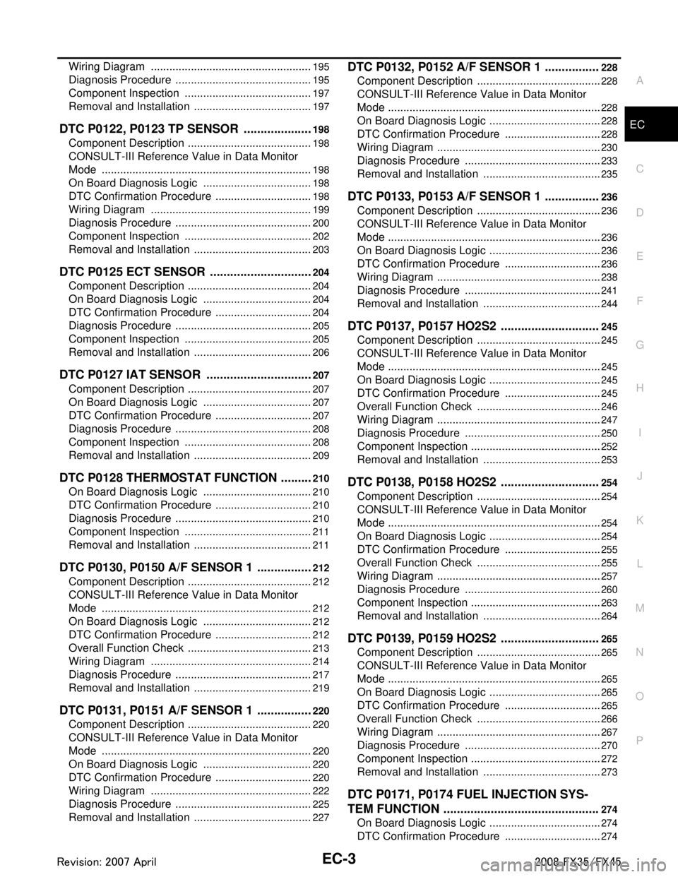
Wiring Diagram ...................................................
..
195
Diagnosis Procedure .............................................195
Component Inspection ..........................................197
Removal and Installation .......................................197
DTC P0122, P0123 TP SENSOR .....................198
Component Description ....................................... ..198
CONSULT-III Reference Value in Data Monitor
Mode ................................................................... ..
198
On Board Diagnosis Logic ....................................198
DTC Confirmation Procedure ................................198
Wiring Diagram .....................................................199
Diagnosis Procedure .............................................200
Component Inspection ..........................................202
Removal and Installation .......................................203
DTC P0125 ECT SENSOR ...............................204
Component Description ....................................... ..204
On Board Diagnosis Logic ....................................204
DTC Confirmation Procedure ................................204
Diagnosis Procedure .............................................205
Component Inspection ..........................................205
Removal and Installation .......................................206
DTC P0127 IAT SENSOR ................................207
Component Description ....................................... ..207
On Board Diagnosis Logic ....................................207
DTC Confirmation Procedure ................................207
Diagnosis Procedure .............................................208
Component Inspection ..........................................208
Removal and Installation .......................................209
DTC P0128 THERMOSTAT FUNCTION ..........210
On Board Diagnosis Logic .................................. ..210
DTC Confirmation Procedure ................................210
Diagnosis Procedure .............................................210
Component Inspection ..........................................211
Removal and Installation .......................................211
DTC P0130, P0150 A/F SENSOR 1 .................212
Component Description ....................................... ..212
CONSULT-III Reference Value in Data Monitor
Mode ................................................................... ..
212
On Board Diagnosis Logic ....................................212
DTC Confirmation Procedure ................................212
Overall Function Check .........................................213
Wiring Diagram .....................................................214
Diagnosis Procedure .............................................217
Removal and Installation .......................................219
DTC P0131, P0151 A/F SENSOR 1 .................220
Component Description ....................................... ..220
CONSULT-III Reference Value in Data Monitor
Mode ................................................................... ..
220
On Board Diagnosis Logic ....................................220
DTC Confirmation Procedure ................................220
Wiring Diagram .....................................................222
Diagnosis Procedure .............................................225
Removal and Installation .......................................227
DTC P0132, P0152 A/F SENSOR 1 ................228
Component Description ....................................... ..228
CONSULT-III Reference Value in Data Monitor
Mode ......................................................................
228
On Board Diagnosis Logic .....................................228
DTC Confirmation Procedure ................................228
Wiring Diagram ......................................................230
Diagnosis Procedure .............................................233
Removal and Installation .......................................235
DTC P0133, P0153 A/F SENSOR 1 ................236
Component Description .........................................236
CONSULT-III Reference Value in Data Monitor
Mode ......................................................................
236
On Board Diagnosis Logic .....................................236
DTC Confirmation Procedure ................................236
Wiring Diagram ......................................................238
Diagnosis Procedure .............................................241
Removal and Installation .......................................244
DTC P0137, P0157 HO2S2 .............................245
Component Description .........................................245
CONSULT-III Reference Value in Data Monitor
Mode ......................................................................
245
On Board Diagnosis Logic .....................................245
DTC Confirmation Procedure ................................245
Overall Function Check .........................................246
Wiring Diagram ......................................................247
Diagnosis Procedure .............................................250
Component Inspection ...........................................252
Removal and Installation .......................................253
DTC P0138, P0158 HO2S2 .............................254
Component Description .........................................254
CONSULT-III Reference Value in Data Monitor
Mode ......................................................................
254
On Board Diagnosis Logic .....................................254
DTC Confirmation Procedure ................................255
Overall Function Check .........................................255
Wiring Diagram ......................................................257
Diagnosis Procedure .............................................260
Component Inspection ...........................................263
Removal and Installation .......................................264
DTC P0139, P0159 HO2S2 .............................265
Component Description .........................................265
CONSULT-III Reference Value in Data Monitor
Mode ......................................................................
265
On Board Diagnosis Logic .....................................265
DTC Confirmation Procedure ................................265
Overall Function Check .........................................266
Wiring Diagram ......................................................267
Diagnosis Procedure .............................................270
Component Inspection ...........................................272
Removal and Installation .......................................273
DTC P0171, P0174 FUEL INJECTION SYS-
TEM FUNCTION ..............................................
274
On Board Diagnosis Logic .....................................274
DTC Confirmation Procedure ................................274
3AA93ABC3ACD3AC03ACA3AC03AC63AC53A913A773A893A873A873A8E3A773A983AC73AC93AC03AC3
3A893A873A873A8F3A773A9D3AAF3A8A3A8C3A863A9D3AAF3A8B3A8C