2008 INFINITI FX35 fuel
[x] Cancel search: fuelPage 1127 of 3924

DI-1
ELECTRICAL
C
DE
F
G H
I
J
L
M
SECTION DI
A
B
DI
N
O P
CONTENTS
DRIVER INFORMATION SYSTEM
SERVICE INFORMATION .. ..........................3
DTC INDEX ..................................................... .....3
U1000 - U1010 .................................................... ......3
B2202 - B2205 ..........................................................3
C1B00 - C1B03 .........................................................3
PRECAUTION .....................................................4
Precaution for Supplemental Restraint System
(SRS) "AIR BAG" and "SEAT BELT PRE-TEN-
SIONER" ............................................................. ......
4
COMBINATION METERS ...................................5
System Description ............................................. ......5
Component Parts and Harness Connector Loca-
tion ............................................................................
8
Arrangement of Combination Meter ..........................9
Circuit Diagram .......................................................10
Wiring Diagram - METER - .....................................11
Terminal and Reference Value for Combination
Meter .......................................................................
13
Terminal and Reference Value for Unified Meter
and A/C Amp ...........................................................
14
Self-Diagnosis Mode of Combination Meter ............14
CONSULT-III Function (METER/M&A) ...................15
Trouble Diagnosis ...................................................15
Symptom Chart .......................................................16
Power Supply and Ground Circuit Inspection .........16
Vehicle Speed Signal Inspection .............................17
Engine Speed Signal Inspection .............................18
Engine Coolant Temperature Signal Inspection ......19
Fuel Level Sensor Signal Inspection .......................19
Fuel Gauge Pointer Fluctuates, Indicator Wrong
Value or Varies ........................................................
21
Fuel Gauge Does Not Move to FULL Position ........21
Odo/Trip Meter and Illumination Control Switch In-
spection ............................................................... ....
21
Electrical Component Inspection .............................21
Removal and Installation of Combination Meter .....22
Disassembly and Assembly of Combination Meter
....
23
Removal and Installation of Odo/Trip Meter and Il-
lumination Control Switch .................................... ....
24
UNIFIED METER AND A/C AMP ......................26
System Description ..................................................26
Schematic ................................................................27
CONSULT-III Function (METER/M&A) ....................27
Power Supply and Ground Circuit Inspection ..........29
DTC [U1000] CAN Communication Circuit ..............30
DTC [B2202] Meter Commun ication Circuit ............30
DTC [B2205] Vehicle Speed Circuit .................... ....32
Removal and Installation of Unified Meter and A/C
Amp .........................................................................
32
WARNING LAMPS ............................................34
System Description .............................................. ....34
Schematic ................................................................35
Wiring Diagram - WARN - .......................................36
Oil Pressure Warning Lamp Stays Off (Ignition
Switch ON) .......................................................... ....
43
Oil Pressure Warning Lamp Does Not Turn Off
(Oil Pressure Is Normal) ...................................... ....
45
Component Inspection .............................................46
A/T INDICATOR ................................................47
System Description ..................................................47
Wiring Diagram - AT/IND - .......................................48
A/T Indicator Is Malfunction .....................................49
WARNING CHIME .............................................51
System Description .............................................. ....51
Component Parts and Harness Connector Loca-
tion ...........................................................................
53
Schematic ................................................................54
Wiring Diagram - CHIME - .......................................55
Terminal and Reference Value for BCM ..................57
Terminal and Reference Value for Unified Meter
and A/C Amp. ...................................................... ....
59
Terminal and Reference Value for Combination
Meter .......................................................................
59
CONSULT-III Function (METER/M&A) ....................60
3AA93ABC3ACD3AC03ACA3AC03AC63AC53A913A773A893A873A873A8E3A773A983AC73AC93AC03AC3
3A893A873A873A8F3A773A9D3AAF3A8A3A8C3A863A9D3AAF3A8B3A8C
Page 1131 of 3924
COMBINATION METERSDI-5
< SERVICE INFORMATION >
C
DE
F
G H
I
J
L
M A
B
DI
N
O P
COMBINATION METERS
System DescriptionINFOID:0000000001328433
UNIFIED METER CONTROL UNIT
Speedometer, odo/trip meter, tachometer, fuel gauge and water temperature gauge are controlled by the
unified meter control unit, which is built into the comb ination meter. Unified meter control unit receives sig-
nals from unified meter and A/C amp.
Warning lamp and indicator lamp of combination meter are controlled by signals drawn from the unified meter and A/C amp.
Odo/trip meter, A/T indicator and ICC system disp lay segments can be checked in self-diagnosis mode.
Meters/gauges can be checked in self-diagnosis mode.
UNIFIED METER AND A/C AMP.
Refer to DI-26, "System Description" in “UNIFIED METER AND A/C AMP”.
POWER SUPPLY AND GROUND CIRCUIT
Power is supplied at all times
through 10A fuse [No. 19, located in the fuse block (J/B)]
to combination meter terminal 8, and
to unified meter and A/C amp. terminal 21.
With the ignition switch in the ON or START position, power is supplied
through 10A fuse [No. 14, located in the fuse block (J/B)]
to combination meter terminal 7,
through 10A fuse [No. 12, located in the fuse block (J/B)]
to unified meter and A/C amp. terminal 22.
With the ignition switch in the ACC or ON position, power is supplied
through 10A fuse [No. 6, located in the fuse block (J/B)]
to combination meter terminal 4,
through 15A fuse [No. 10, located in the fuse block (J/B)], and
through 15A fuse [No. 11, located in the fuse block (J/B)]
to unified meter and A/C amp. terminal 46.
Ground is supplied
to combination meter terminals 5, 6 and 15
through grounds M35, M45 and M85,
to unified meter and A/C amp. terminals 29 and 30
through grounds M35, M45 and M85.
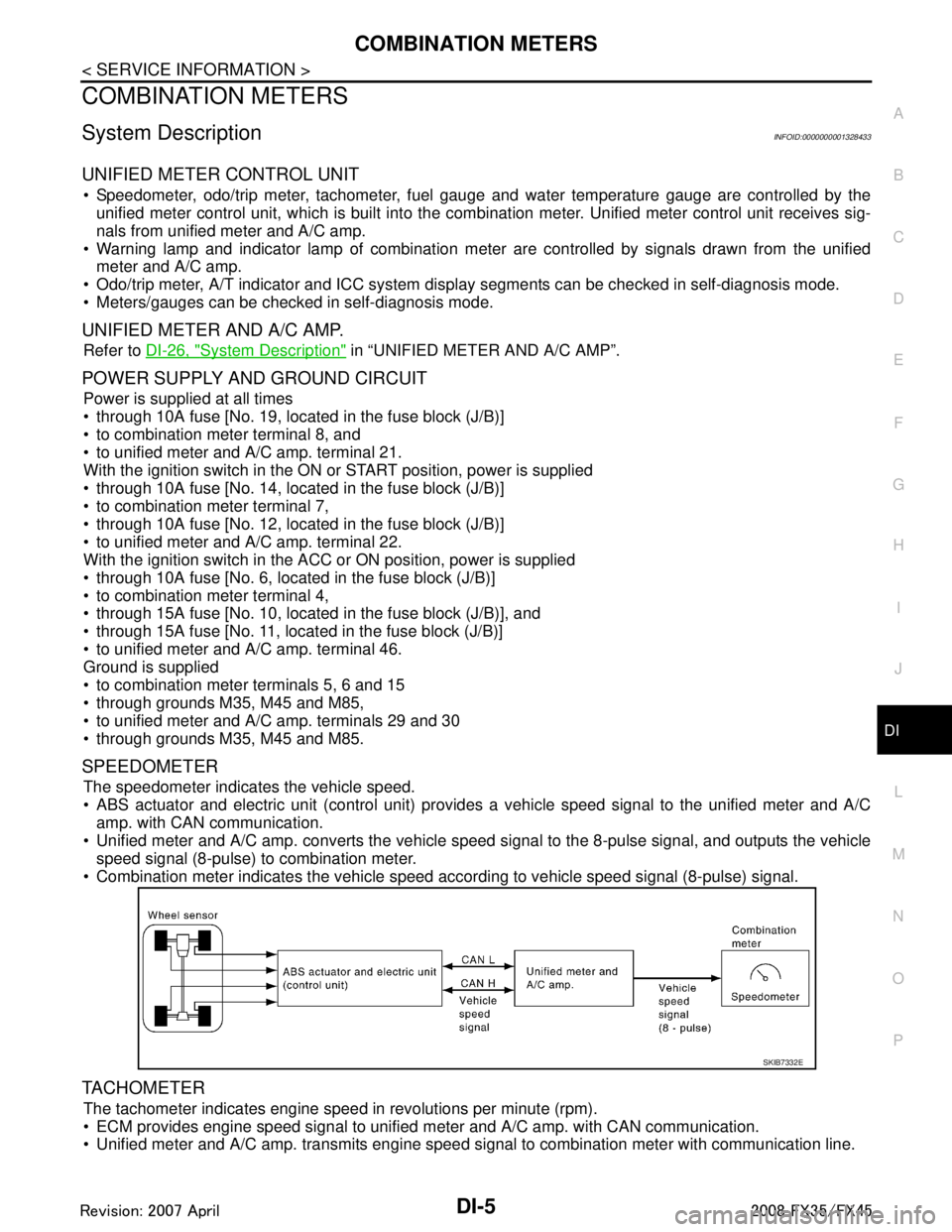
SPEEDOMETER
The speedometer indicates the vehicle speed.
ABS actuator and electric unit (control unit) provides a vehicle speed signal to the unified meter and A/C amp. with CAN communication.
Unified meter and A/C amp. converts the vehicle s peed signal to the 8-pulse signal, and outputs the vehicle
speed signal (8-pulse) to combination meter.
Combination meter indicates the vehicle speed according to vehicle speed signal (8-pulse) signal.
TACHOMETER
The tachometer indicates engine speed in revolutions per minute (rpm).
ECM provides engine speed signal to unified meter and A/C amp. with CAN communication.
Unified meter and A/C amp. transmits engine speed signal to combination meter with communication line.
SKIB7332E
3AA93ABC3ACD3AC03ACA3AC03AC63AC53A913A773A893A873A873A8E3A773A983AC73AC93AC03AC3
3A893A873A873A8F3A773A9D3AAF3A8A3A8C3A863A9D3AAF3A8B3A8C
Page 1132 of 3924
DI-6
< SERVICE INFORMATION >
COMBINATION METERS
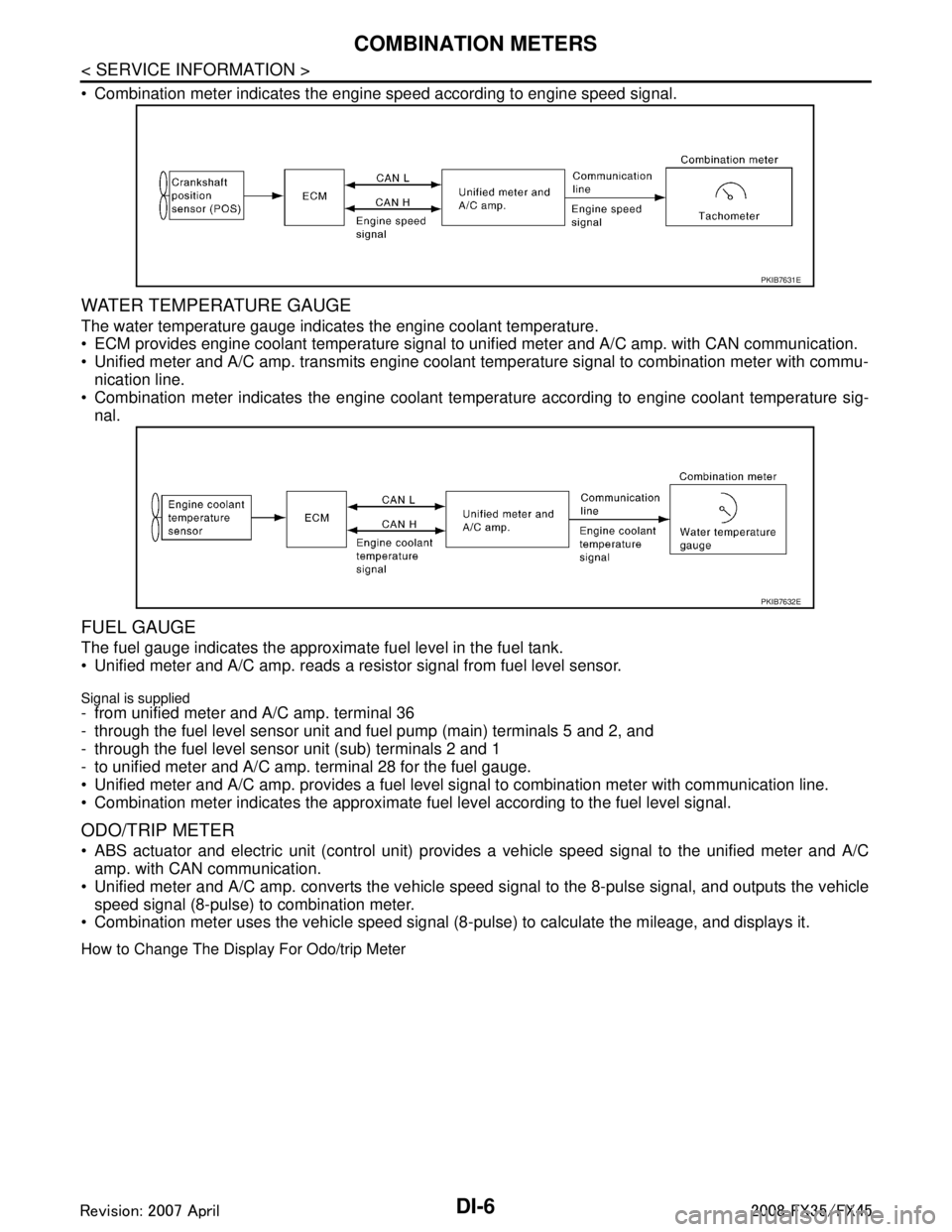
Combination meter indicates the engine speed according to engine speed signal.
WATER TEMPERATURE GAUGE
The water temperature gauge indicates the engine coolant temperature.
ECM provides engine coolant temperature signal to unified meter and A/C amp. with CAN communication.
Unified meter and A/C amp. transmits engine coolant temperature signal to combination meter with commu-
nication line.
Combination meter indicates the engine coolant temper ature according to engine coolant temperature sig-
nal.
FUEL GAUGE
The fuel gauge indicates the approximate fuel level in the fuel tank.
Unified meter and A/C amp. reads a resistor signal from fuel level sensor.
Signal is supplied- from unified meter and A/C amp. terminal 36
- through the fuel level sensor unit and fuel pump (main) terminals 5 and 2, and
- through the fuel level sensor unit (sub) terminals 2 and 1
- to unified meter and A/C amp. terminal 28 for the fuel gauge.
Unified meter and A/C amp. provides a fuel level signal to combination meter with communication line.
Combination meter indicates the approximate fuel level according to the fuel level signal.
ODO/TRIP METER
ABS actuator and electric unit (control unit) provi des a vehicle speed signal to the unified meter and A/C
amp. with CAN communication.
Unified meter and A/C amp. converts the vehicle s peed signal to the 8-pulse signal, and outputs the vehicle
speed signal (8-pulse) to combination meter.
Combination meter uses the vehicle speed signal (8- pulse) to calculate the mileage, and displays it.
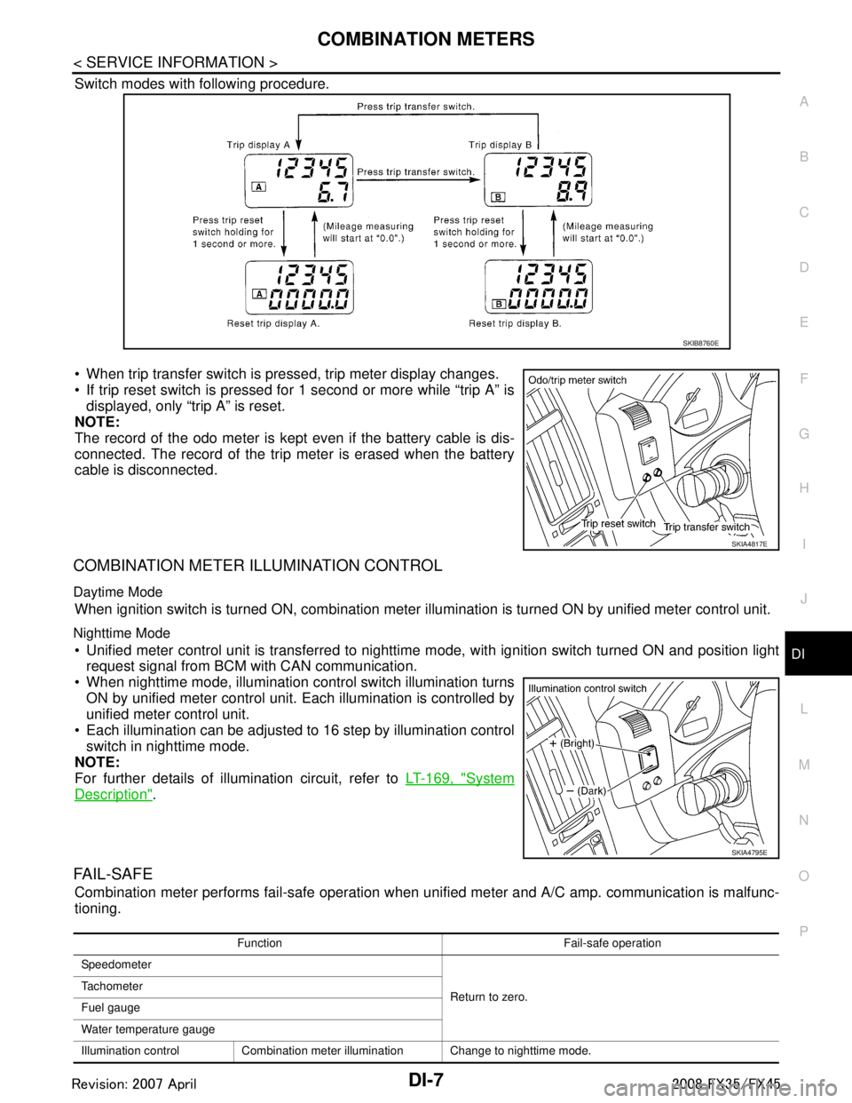
How to Change The Display For Odo/trip Meter
PKIB7631E
PKIB7632E
3AA93ABC3ACD3AC03ACA3AC03AC63AC53A913A773A893A873A873A8E3A773A983AC73AC93AC03AC3
3A893A873A873A8F3A773A9D3AAF3A8A3A8C3A863A9D3AAF3A8B3A8C
Page 1133 of 3924
COMBINATION METERSDI-7
< SERVICE INFORMATION >
C
DE
F
G H
I
J
L
M A
B
DI
N
O P
Switch modes with following procedure.
When trip transfer switch is pressed, trip meter display changes.
If trip reset switch is pressed for 1 second or more while “trip A” is displayed, only “trip A” is reset.
NOTE:
The record of the odo meter is kept even if the battery cable is dis-
connected. The record of the trip meter is erased when the battery
cable is disconnected.
COMBINATION METER ILLUMINATION CONTROL
Daytime Mode
When ignition switch is turned ON, combination meter il lumination is turned ON by unified meter control unit.
Nighttime Mode
Unified meter control unit is transferred to nighttime mode, with ignitio\
n switch turned ON and position light
request signal from BCM with CAN communication.
When nighttime mode, illumination c ontrol switch illumination turns
ON by unified meter control unit. Each illumination is controlled by
unified meter control unit.
Each illumination can be adjusted to 16 step by illumination control switch in nighttime mode.
NOTE:
For further details of illumination circuit, refer to LT-169, "
System
Description".
FA I L - S A F E
Combination meter performs fail-safe operation when unified meter and A/C amp. communication is malfunc-
tioning.
SKIB8760E
SKIA4817E
SKIA4795E
Function Fail-safe operation
Speedometer
Return to zero.
Tachometer
Fuel gauge
Water temperature gauge
Illumination control Combination meter illumination Change to nighttime mode.
3AA93ABC3ACD3AC03ACA3AC03AC63AC53A913A773A893A873A873A8E3A773A983AC73AC93AC03AC3
3A893A873A873A8F3A773A9D3AAF3A8A3A8C3A863A9D3AAF3A8B3A8C
Page 1140 of 3924
DI-14
< SERVICE INFORMATION >
COMBINATION METERS
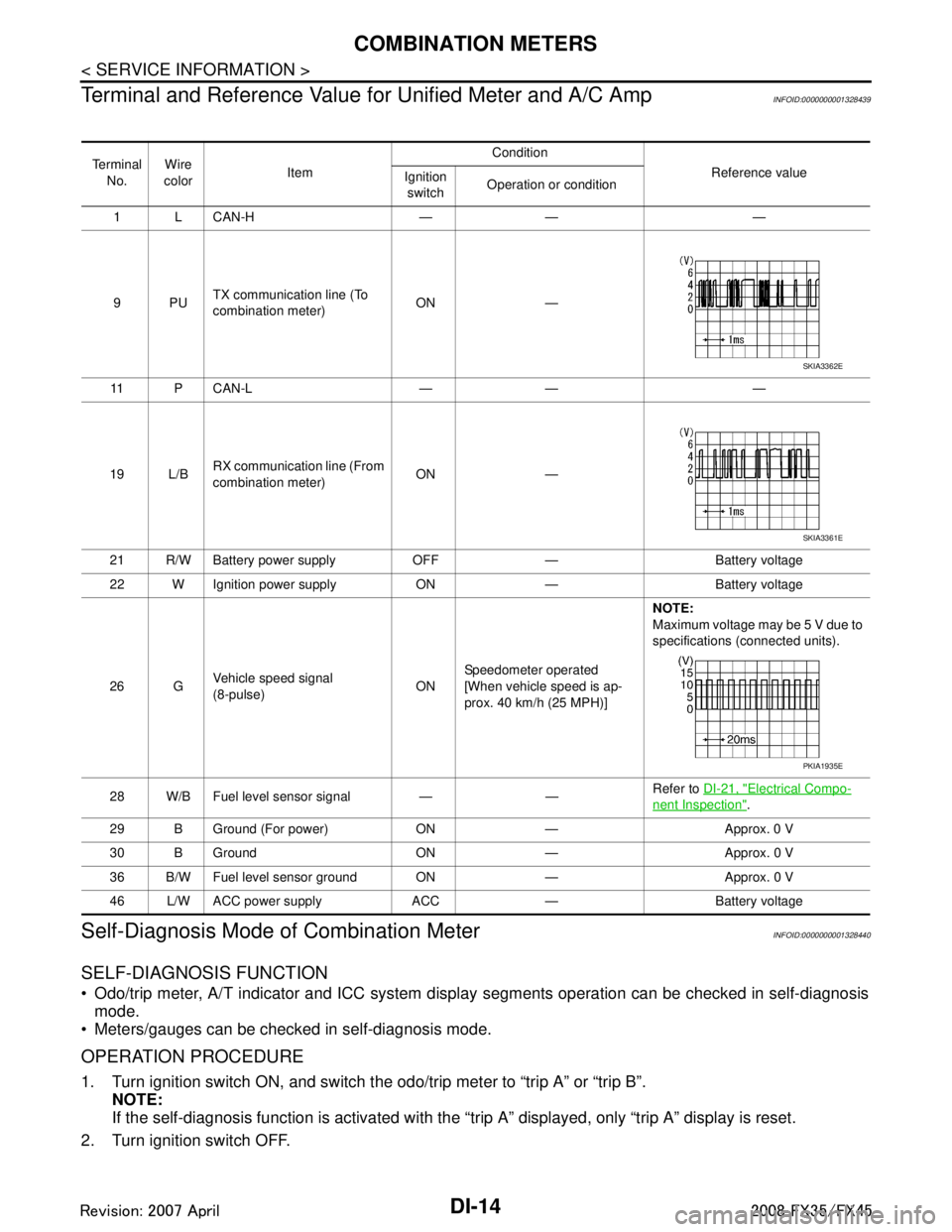
Terminal and Reference Value for Unified Meter and A/C Amp
INFOID:0000000001328439
Self-Diagnosis Mode of Combination MeterINFOID:0000000001328440
SELF-DIAGNOSIS FUNCTION
Odo/trip meter, A/T indicator and ICC system disp lay segments operation can be checked in self-diagnosis
mode.
Meters/gauges can be checked in self-diagnosis mode.
OPERATION PROCEDURE
1. Turn ignition switch ON, and switch the odo/trip meter to “trip A” or “trip B”. NOTE:
If the self-diagnosis function is activated with the “t rip A” displayed, only “trip A” display is reset.
2. Turn ignition switch OFF.
Te r m i n a l No. Wire
color Item Condition
Reference value
Ignition
switch Operation or condition
1 L CAN-H — — —
9PU TX communication line (To
combination meter) ON —
11 P C A N - L — — —
19 L/B RX communication line (From
combination meter) ON —
21 R/W Battery power supply OFF — Battery voltage
22 W Ignition power supply ON — Battery voltage
26 G Vehicle speed signal
(8-pulse)
ONSpeedometer operated
[When vehicle speed is ap-
prox. 40 km/h (25 MPH)] NOTE:
Maximum voltage may be 5 V due to
specifications (connected units).
28 W/B Fuel level sensor signal — — Refer to
DI-21, "
Electrical Compo-
nent Inspection".
29 B Ground (For power) ON — Approx. 0 V
30 B Ground ON — Approx. 0 V
36 B/W Fuel level sensor ground ON — Approx. 0 V
46 L/W ACC power supply ACC — Battery voltage
SKIA3362E
SKIA3361E
PKIA1935E
3AA93ABC3ACD3AC03ACA3AC03AC63AC53A913A773A893A873A873A8E3A773A983AC73AC93AC03AC3
3A893A873A873A8F3A773A9D3AAF3A8A3A8C3A863A9D3AAF3A8B3A8C
Page 1141 of 3924

COMBINATION METERSDI-15
< SERVICE INFORMATION >
C
DE
F
G H
I
J
L
M A
B
DI
N
O P
3. Turn ignition switch ON while pressing trip transfer switch and trip reset switch at the same time.
4. After ignition switch is turned ON, release trip transfer switch and trip reset switch (within 7 seconds after the ignition switch is
turned ON).
5. All the segments on the odo/trip meter, A/T indi cator and ICC system display illuminates, and simulta-
neously the low-fuel warning lamp indicator illuminates. At this time, the unified meter control unit is turned
to self-diagnosis mode.
NOTE:
Check odo/trip meter switch and combination meter power supply and ground circuit when self-diagno-
sis mode of combination meter does not start. Replace combination meter if the results of the check are
normal.
If any of the segments are not disp layed, replace combination meter.
6. Each meter/gauge activates during pressing trip reset switch. (Then low-fuel warning lamp turns OFF.)
NOTE:
If any of the meters/gauges are not activated, replace thecombination meter.
The figure is reference.
CONSULT-III Function (METER/M&A)INFOID:0000000001328441
Refer to DI-27, "CONSULT-III Function (METER/M&A)" in “UNIFIED METER AND A/C AMP”.
Trouble DiagnosisINFOID:0000000001328442
HOW TO PERFORM TROUBLE DIAGNOSIS
1. Confirm the symptom or customer complaint.
2. Perform preliminary check. Refer to "PRELIMINARY CHECK".
3. According to the symptom chart, repair or replace the cause of the symptom. Refer to DI-16, "
Symptom
Chart".
4. Does the meter operate normally? If so, GO TO 5. If not, GO TO 2.
5. INSPECTION END
PRELIMINARY CHECK
1.CHECK OPERATION OF SELF-DIAGNOSIS MODE (COMBINATION METER)
SKIA4817E
SKIA6170E
SKIA4831E
3AA93ABC3ACD3AC03ACA3AC03AC63AC53A913A773A893A873A873A8E3A773A983AC73AC93AC03AC3
3A893A873A873A8F3A773A9D3AAF3A8A3A8C3A863A9D3AAF3A8B3A8C
Page 1142 of 3924
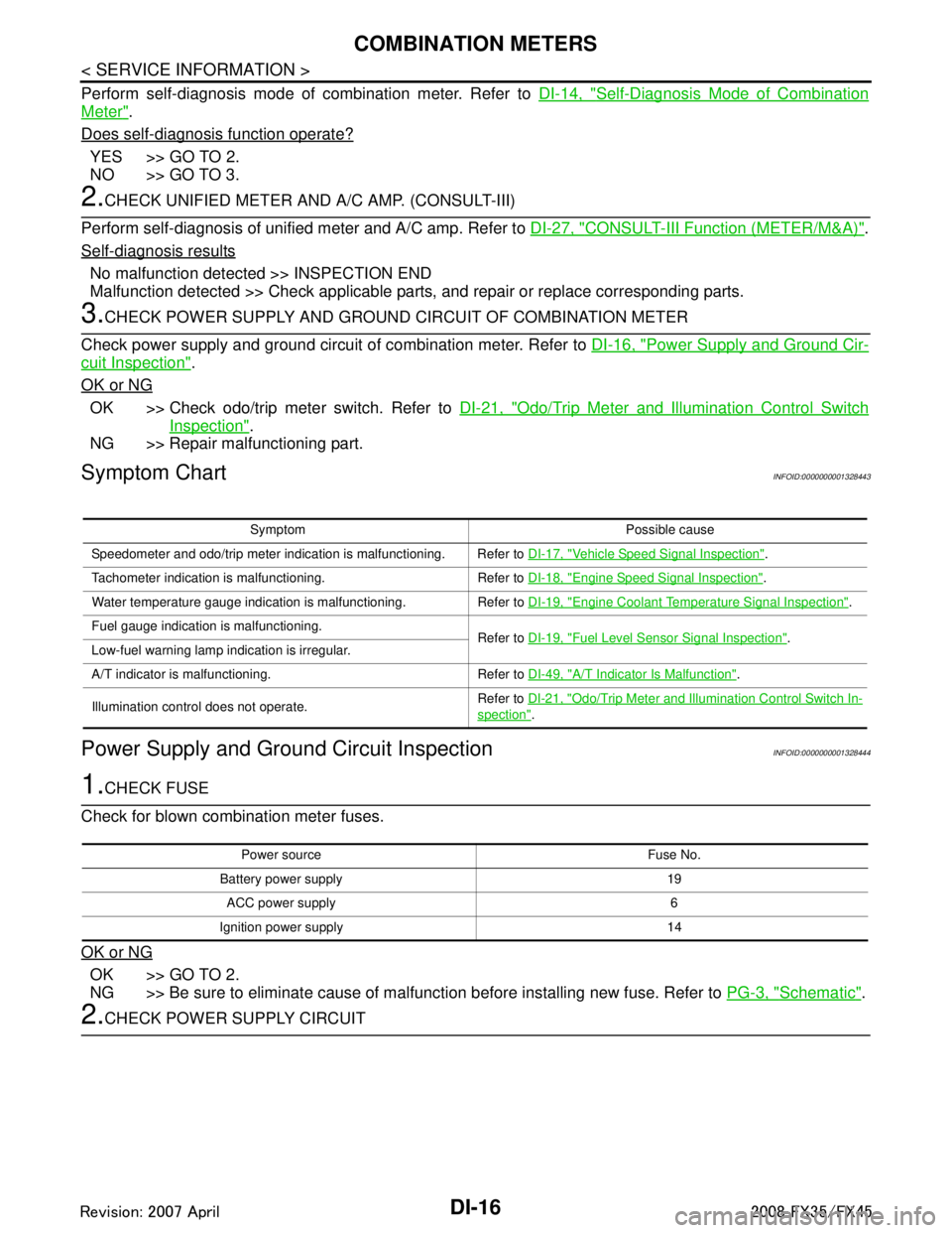
DI-16
< SERVICE INFORMATION >
COMBINATION METERS
Perform self-diagnosis mode of combination meter. Refer to DI-14, "Self-Diagnosis Mode of Combination
Meter".
Does self-diagnosis function operate?
YES >> GO TO 2.
NO >> GO TO 3.
2.CHECK UNIFIED METER AND A/C AMP. (CONSULT-III)
Perform self-diagnosis of unified meter and A/C amp. Refer to DI-27, "
CONSULT-III Function (METER/M&A)".
Self-diagnosis results
No malfunction detected >> INSPECTION END
Malfunction detected >> Check applicable parts, and repair or replace corresponding parts.
3.CHECK POWER SUPPLY AND GROUND CIRCUIT OF COMBINATION METER
Check power supply and ground circuit of combination meter. Refer to DI-16, "
Power Supply and Ground Cir-
cuit Inspection".
OK or NG
OK >> Check odo/trip meter switch. Refer to DI-21, "Odo/Trip Meter and Illumination Control Switch
Inspection".
NG >> Repair malfunctioning part.
Symptom ChartINFOID:0000000001328443
Power Supply and Ground Circuit InspectionINFOID:0000000001328444
1.CHECK FUSE
Check for blown combination meter fuses.
OK or NG
OK >> GO TO 2.
NG >> Be sure to eliminate cause of malfunction before installing new fuse. Refer to PG-3, "
Schematic".
2.CHECK POWER SUPPLY CIRCUIT
Symptom Possible cause
Speedometer and odo/trip meter indication is malfunctioning. Refer to DI-17, "
Vehicle Speed Signal Inspection".
Tachometer indication is malfunctioning. Refer to DI-18, "
Engine Speed Signal Inspection".
Water temperature gauge indication is malfunctioning. Refer to DI-19, "
Engine Coolant Temperature Signal Inspection".
Fuel gauge indication is malfunctioning. Refer to DI-19, "
Fuel Level Sensor Signal Inspection".
Low-fuel warning lamp indication is irregular.
A/T indicator is malfunctioning. Refer to DI-49, "
A/T Indicator Is Malfunction".
Illumination control does not operate. Refer to
DI-21, "
Odo/Trip Meter and Illumination Control Switch In-
spection".
Power source Fuse No.
Battery power supply 19 ACC power supply 6
Ignition power supply 14
3AA93ABC3ACD3AC03ACA3AC03AC63AC53A913A773A893A873A873A8E3A773A983AC73AC93AC03AC3
3A893A873A873A8F3A773A9D3AAF3A8A3A8C3A863A9D3AAF3A8B3A8C
Page 1145 of 3924
COMBINATION METERSDI-19
< SERVICE INFORMATION >
C
DE
F
G H
I
J
L
M A
B
DI
N
O P
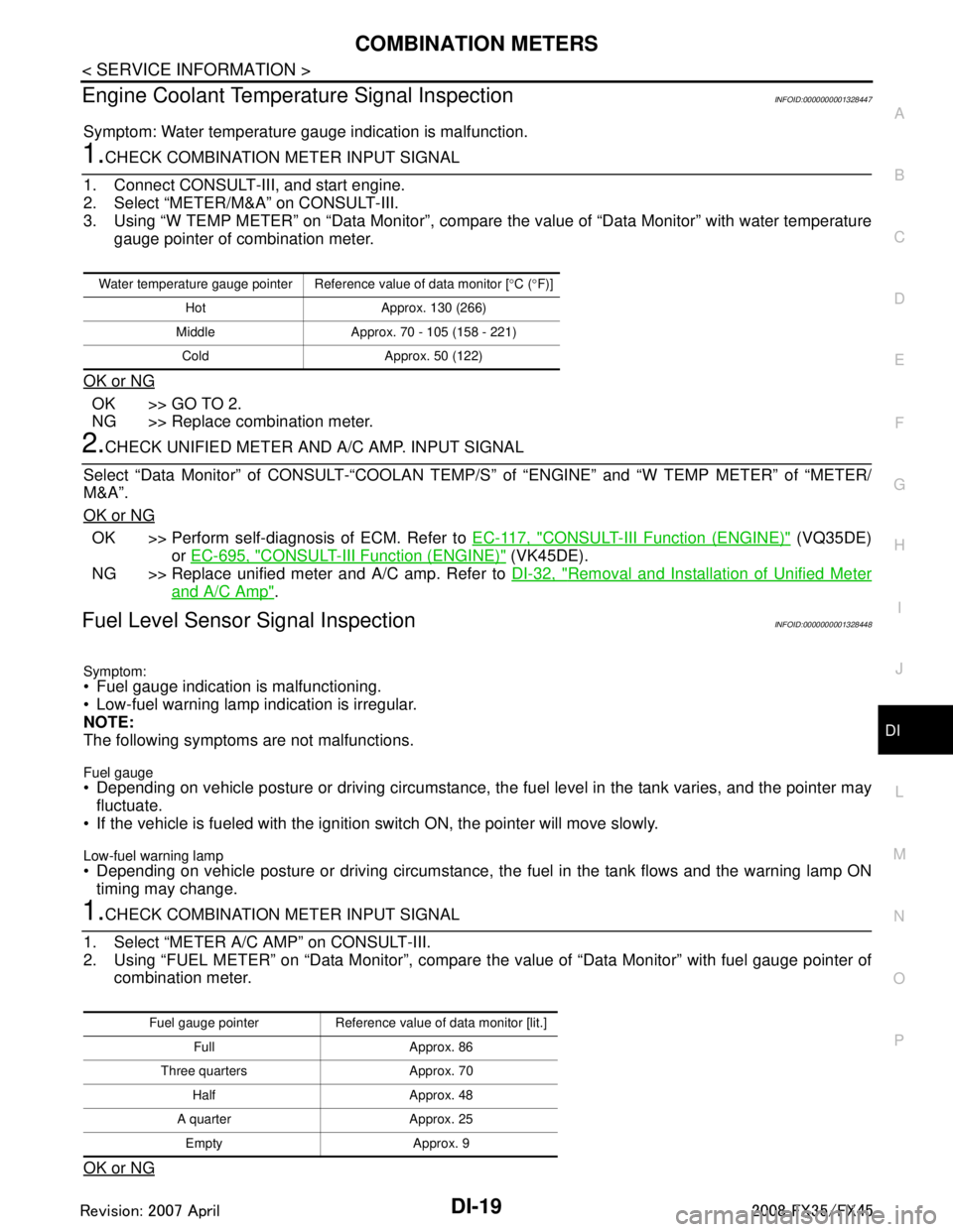
Engine Coolant Temperature Signal InspectionINFOID:0000000001328447
Symptom: Water temperature gauge indication is malfunction.
1.CHECK COMBINATION METER INPUT SIGNAL
1. Connect CONSULT-III, and start engine.
2. Select “METER/M&A” on CONSULT-III.
3. Using “W TEMP METER” on “Data Monitor”, compare the value of “Data Monitor” with water temperature
gauge pointer of combination meter.
OK or NG
OK >> GO TO 2.
NG >> Replace combination meter.
2.CHECK UNIFIED METER AND A/C AMP. INPUT SIGNAL
Select “Data Monitor” of CONSULT-“COOLAN TEMP/S ” of “ENGINE” and “W TEMP METER” of “METER/
M&A”.
OK or NG
OK >> Perform self-diagnosis of ECM. Refer to EC-117, "CONSULT-III Function (ENGINE)" (VQ35DE)
or EC-695, "
CONSULT-III Function (ENGINE)" (VK45DE).
NG >> Replace unified meter and A/C amp. Refer to DI-32, "
Removal and Installation of Unified Meter
and A/C Amp".
Fuel Level Sensor Signal InspectionINFOID:0000000001328448
Symptom:
Fuel gauge indication is malfunctioning.
Low-fuel warning lamp indication is irregular.
NOTE:
The following symptoms are not malfunctions.
Fuel gauge Depending on vehicle posture or driving circumstance, the fuel level in the tank varies, and the pointer may
fluctuate.
If the vehicle is fueled with the ignition switch ON, the pointer will move slowly.
Low-fuel warning lamp
Depending on vehicle posture or driving circumstance, t he fuel in the tank flows and the warning lamp ON
timing may change.
1.CHECK COMBINATION METER INPUT SIGNAL
1. Select “METER A/C AMP” on CONSULT-III.
2. Using “FUEL METER” on “Data Monitor”, compare t he value of “Data Monitor” with fuel gauge pointer of
combination meter.
OK or NG
Water temperature gauge pointer Reference value of data monitor [ °C ( °F)]
Hot Approx. 130 (266)
Middle Approx. 70 - 105 (158 - 221) Cold Approx. 50 (122)
Fuel gauge pointer Reference value of data monitor [lit.] Full Approx. 86
Three quarters Approx. 70 Half Approx. 48
A quarter Approx. 25 Empty Approx. 9
3AA93ABC3ACD3AC03ACA3AC03AC63AC53A913A773A893A873A873A8E3A773A983AC73AC93AC03AC3
3A893A873A873A8F3A773A9D3AAF3A8A3A8C3A863A9D3AAF3A8B3A8C