2008 INFINITI FX35 wiring
[x] Cancel search: wiringPage 2889 of 3924
SERVICE INFORMATION FOR ELECTRICAL INCIDENTGI-27
< SERVICE INFORMATION >
C
DE
F
G H
I
J
K L
M B
GI
N
O P
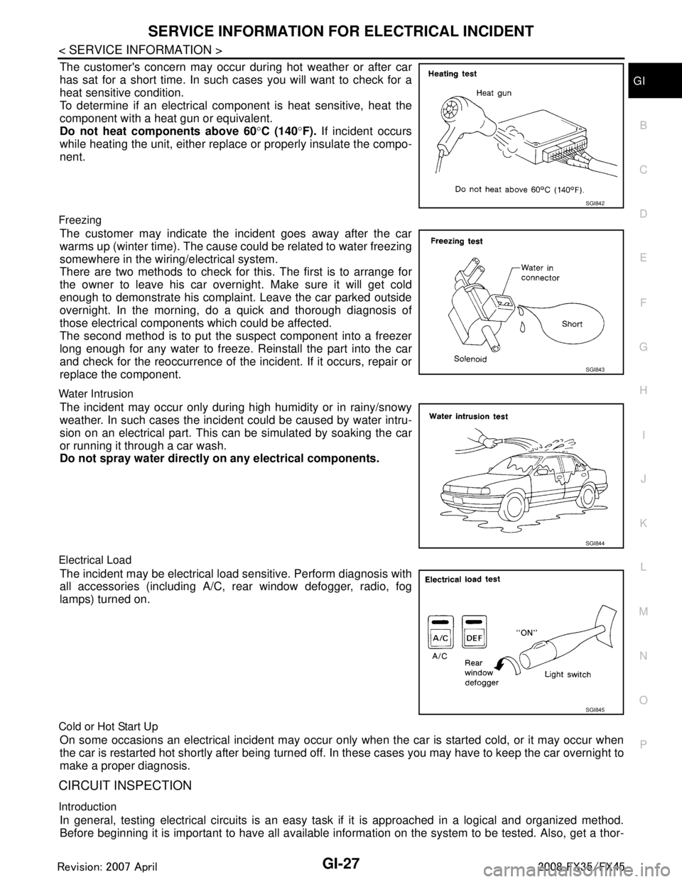
The customer's concern may occur during hot weather or after car
has sat for a short time. In such cases you will want to check for a
heat sensitive condition.
To determine if an electrical com ponent is heat sensitive, heat the
component with a heat gun or equivalent.
Do not heat components above 60 °C (140 °F). If incident occurs
while heating the unit, either replac e or properly insulate the compo-
nent.
Freezing
The customer may indicate the incident goes away after the car
warms up (winter time). The cause could be related to water freezing
somewhere in the wiring/electrical system.
There are two methods to check for this. The first is to arrange for
the owner to leave his car overnight. Make sure it will get cold
enough to demonstrate his complaint. Leave the car parked outside
overnight. In the morning, do a quick and thorough diagnosis of
those electrical components which could be affected.
The second method is to put the suspect component into a freezer
long enough for any water to freeze. Reinstall the part into the car
and check for the reoccurrence of the incident. If it occurs, repair or
replace the component.
Water Intrusion
The incident may occur only during high humidity or in rainy/snowy
weather. In such cases the incident could be caused by water intru-
sion on an electrical part. This c an be simulated by soaking the car
or running it through a car wash.
Do not spray water directly on any electrical components.
Electrical Load
The incident may be electrical load sensitive. Perform diagnosis with
all accessories (including A/C, rear window defogger, radio, fog
lamps) turned on.
Cold or Hot Start Up
On some occasions an electrical incident may occur only when the car is started cold, or it may occur when
the car is restarted hot shortly after being turned off. In these cases you may have to keep the car overnight to
make a proper diagnosis.
CIRCUIT INSPECTION
Introduction
In general, testing electrical circuits is an easy ta sk if it is approached in a logical and organized method.
Before beginning it is important to have all available in formation on the system to be tested. Also, get a thor-
SGI842
SGI843
SGI844
SGI845
3AA93ABC3ACD3AC03ACA3AC03AC63AC53A913A773A893A873A873A8E3A773A983AC73AC93AC03AC3
3A893A873A873A8F3A773A9D3AAF3A8A3A8C3A863A9D3AAF3A8B3A8C
Page 2890 of 3924
GI-28
< SERVICE INFORMATION >
SERVICE INFORMATION FOR ELECTRICAL INCIDENT
ough understanding of system operation. Then you will be able to use the appropriate equipment and follow
the correct test procedure.
You may have to simulate vehicle vibrations while test ing electrical components. Gently shake the wiring har-
ness or electrical component to do this.
NOTE:
Refer to “How to Check Terminal” to probe or check terminal.
Testing for “Opens” in the Circuit
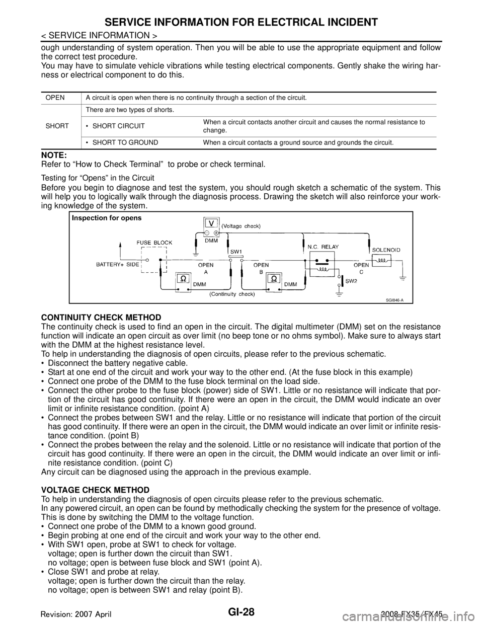
Before you begin to diagnose and test the system, you should rough sketch a schematic of the system. This
will help you to logically walk through the diagnosis process. Drawing the sketch will also reinforce your work-
ing knowledge of the system.
CONTINUITY CHECK METHOD
The continuity check is used to find an open in the circ uit. The digital multimeter (DMM) set on the resistance
function will indicate an open circuit as over limit (no beep tone or no ohms symbo\
l). Make sure to always start
with the DMM at the highest resistance level.
To help in understanding the diagnosis of open circui ts, please refer to the previous schematic.
Disconnect the battery negative cable.
Start at one end of the circuit and work your way to the other end. (At the fuse block in this example)
Connect one probe of the DMM to the fuse block terminal on the load side.
Connect the other probe to the fuse block (power) side of SW1. Little or no resistance will indicate that por-
tion of the circuit has good continuity. If there were an open in the circuit, the DMM would indicate an over
limit or infinite resistance condition. (point A)
Connect the probes between SW1 and the relay. Little or no resistance will indicate that portion of the circuit
has good continuity. If there were an open in the circuit, t he DMM would indicate an over limit or infinite resis-
tance condition. (point B)
Connect the probes between the relay and the solenoid. Little or no resistance will indicate that portion of the
circuit has good continuity. If there were an open in the ci rcuit, the DMM would indicate an over limit or infi-
nite resistance condition. (point C)
Any circuit can be diagnosed using the approach in the previous example.
VOLTAGE CHECK METHOD
To help in understanding the diagnosis of open circui ts please refer to the previous schematic.
In any powered circuit, an open can be found by methodica lly checking the system for the presence of voltage.
This is done by switching the DMM to the voltage function.
Connect one probe of the DMM to a known good ground.
Begin probing at one end of the circuit and work your way to the other end.
With SW1 open, probe at SW1 to check for voltage.
voltage; open is further down the circuit than SW1.
no voltage; open is between fuse block and SW1 (point A).
Close SW1 and probe at relay.
voltage; open is further down the circuit than the relay.
no voltage; open is between SW1 and relay (point B).
OPEN A circuit is open when there is no continuity through a section of the circuit.
SHORT There are two types of shorts.
SHORT CIRCUIT
When a circuit contacts another circuit and causes the normal resistance to
change.
SHORT TO GROUND When a circuit contacts a ground source and grounds the circuit.
SGI846-A
3AA93ABC3ACD3AC03ACA3AC03AC63AC53A913A773A893A873A873A8E3A773A983AC73AC93AC03AC3
3A893A873A873A8F3A773A9D3AAF3A8A3A8C3A863A9D3AAF3A8B3A8C
Page 2892 of 3924
GI-30
< SERVICE INFORMATION >
SERVICE INFORMATION FOR ELECTRICAL INCIDENT
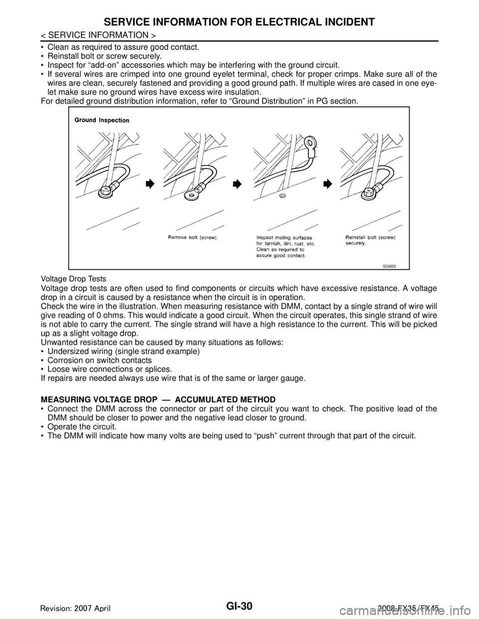
Clean as required to assure good contact.
Reinstall bolt or screw securely.
Inspect for “add-on” accessories which may be interfering with the ground circuit.
If several wires are crimped into one ground eyelet terminal, check for proper crimps. Make sure all of thewires are clean, securely fastened and providing a good ground path. If multiple wires are cased in one eye-
let make sure no ground wires have excess wire insulation.
For detailed ground distribution information, re fer to “Ground Distribution” in PG section.
Voltage Drop Tests
Voltage drop tests are often used to find components or circuits which have excessive resistance. A voltage
drop in a circuit is caused by a resistance when the circuit is in operation.
Check the wire in the illustration. When measuring resist ance with DMM, contact by a single strand of wire will
give reading of 0 ohms. This would indicate a good circui t. When the circuit operates, this single strand of wire
is not able to carry the current. The single strand will have a high resistance to the current. This will be picked
up as a slight voltage drop.
Unwanted resistance can be caused by many situations as follows:
Undersized wiring (single strand example)
Corrosion on switch contacts
Loose wire connections or splices.
If repairs are needed always use wire that is of the same or larger gauge.
MEASURING VOLTAGE DROP — ACCUMULATED METHOD
Connect the DMM across the connector or part of the ci rcuit you want to check. The positive lead of the
DMM should be closer to power and the negative lead closer to ground.
Operate the circuit.
The DMM will indicate how many volts are being used to “push” current through that part of the circuit.
SGI853
3AA93ABC3ACD3AC03ACA3AC03AC63AC53A913A773A893A873A873A8E3A773A983AC73AC93AC03AC3
3A893A873A873A8F3A773A9D3AAF3A8A3A8C3A863A9D3AAF3A8B3A8C
Page 2897 of 3924
CONSULT-III/GST CHECKING SYSTEMGI-35
< SERVICE INFORMATION >
C
DE
F
G H
I
J
K L
M B
GI
N
O P
CONSULT-III/GST Data Link Connector (DLC) CircuitINFOID:0000000001572195
INSPECTION PROCEDURE
If the CONSULT-III/GST cannot diagnose the system properly, check the following items.
NOTE:
The DDL1 and DDL2 circuits from DLC pins 12, 13, 14 and 15 may be connected to more than one system. A
short in a DDL circuit connected to a control unit in one system may affect CONSULT-III access to other sys-
tems.
If the GST cannot operate properly, check the circuit based on the information of SAE J1962 and ISO 15031-
3.
Symptom Check item
CONSULT-III/GST cannot ac-
cess any system. CONSULT-III/GST DLC power supply circuit (Terminal 8 and 16) and ground circuit (Terminal 4 and
5)
CONSULT-III cannot access in-
dividual system. (Other sys-
tems can be accessed.) Power supply and ground circuit for the control unit of the system (For detailed circuit, refer to wiring
diagram for each system.)
Open or short circuit between the system and CONSULT-III DLC (For detailed circuit, refer to wiring
diagram for each system.)
Open or short circuit CAN communication line. Refer to LAN-14, "
Trouble Diagnosis Flow Chart".
3AA93ABC3ACD3AC03ACA3AC03AC63AC53A913A773A893A873A873A8E3A773A983AC73AC93AC03AC3
3A893A873A873A8F3A773A9D3AAF3A8A3A8C3A863A9D3AAF3A8B3A8C
Page 2898 of 3924
GI-36
< SERVICE INFORMATION >
CONSULT-III/GST CHECKING SYSTEM
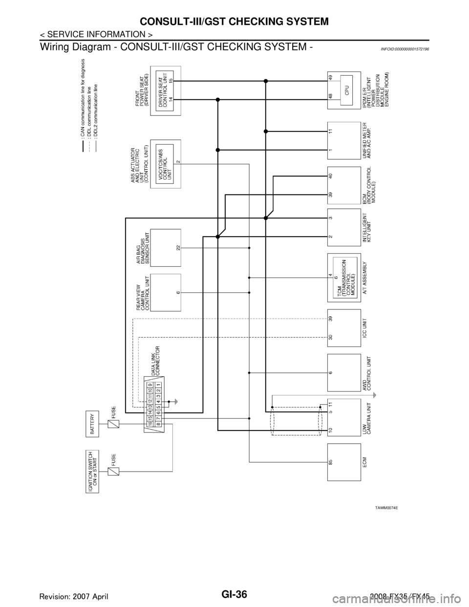
Wiring Diagram - CONSULT-I II/GST CHECKING SYSTEM -
INFOID:0000000001572196
TAWM0074E
3AA93ABC3ACD3AC03ACA3AC03AC63AC53A913A773A893A873A873A8E3A773A983AC73AC93AC03AC3
3A893A873A873A8F3A773A9D3AAF3A8A3A8C3A863A9D3AAF3A8B3A8C
Page 2914 of 3924

GW-1
BODY
C
DE
F
G H
J
K L
M
SECTION GW
A
B
GW
N
O P
CONTENTS
GLASSES, WINDOW SYSTEM & MIRRORS
SERVICE INFORMATION .. ..........................3
PRECAUTIONS .............................................. .....3
Precaution for Supplemental Restraint System
(SRS) "AIR BAG" and "SEAT BELT PRE-TEN-
SIONER" ............................................................. ......
3
Precaution for Procedure without Cowl Top Cover ......3
Handling for Adhesive and Primer ............................3
PREPARATION ...................................................4
Special Service Tool ........................................... ......4
Commercial Service Tool ..........................................4
SQUEAK AND RATTLE TROUBLE DIAG-
NOSES ................................................................
5
Work Flow ........................................................... ......5
Generic Squeak and Rattle Troubleshooting ............7
Diagnostic Worksheet ...............................................9
WINDSHIELD GLASS ........................................11
Removal and Installation ..................................... ....11
BACK DOOR WINDOW GLASS ........................13
Removal and Installation ..................................... ....13
POWER WINDOW SYSTEM ..............................15
Component Parts and Harness Connector Loca-
tion ...................................................................... ....
15
System Description .................................................15
CAN Communication System Description ...............18
CAN Communication Unit .......................................19
Schematic ...............................................................19
Wiring Diagram - WINDOW - ..................................20
Terminal and Reference Value for BCM .................23
Terminal and Reference Value for Power Window
Main Switch .............................................................
24
Terminal and Reference Value for Front Power
Window Switch (Passenger Side) ...........................
25
CONSULT-III Function ............................................26
Work Flow ...............................................................27
Trouble Diagnosis Symptom Chart .........................27
Check BCM Power Supply and Ground Circuit .......28
Check Power Window Main Switch Power Supply
Circuit .................................................................. ....
28
Check Front Power Window Switch (Passenger
Side) Power Supply and Ground Circuit ..................
30
Check Front Power Window Motor (Driver Side)
Circuit ......................................................................
30
Check Front Power Window Motor (Passenger
Side) Circuit .............................................................
31
Check rear Power Window Motor (LH) Circuit .........32
Check Rear Power Window Motor (RH) Circuit .......34
Check Limit Switch Circuit (Driver Side) .............. ....36
Check Limit Switch Circuit (Passenger Side) ..........37
Check Encoder Circuit (Driver Side) ........................39
Check Encoder Circuit (Passenger Side) ................40
Check Door Switch ..................................................42
Check Front Door Key Cylinder Switch ...................43
Check Power Window Serial Link (Passenger
Side) ........................................................................
45
Check Power Window Lock Switch .........................46
SIDE WINDOW GLASS ....................................48
Removal and Installation .........................................48
FRONT DOOR GLASS AND REGULATOR .....50
Removal and Installation .........................................50
Disassembly and assembly .....................................52
Inspection after Installation ......................................52
REAR DOOR GLASS AND REGULATOR .......54
Removal and Installation .........................................54
Disassembly and assembly .....................................56
Fitting Inspection .....................................................56
INSIDE MIRROR ...............................................57
Wiring Diagram - I/MIRR - .......................................57
Removal and Installation .........................................58
REAR WINDOW DEFOGGER ..........................60
Component Parts and Harness Connector Loca-
tion ...........................................................................
60
System Description ..................................................60
CAN Communication System Description ...............61
3AA93ABC3ACD3AC03ACA3AC03AC63AC53A913A773A893A873A873A8E3A773A983AC73AC93AC03AC3
3A893A873A873A8F3A773A9D3AAF3A8A3A8C3A863A9D3AAF3A8B3A8C
Page 2915 of 3924

GW-2
CAN Communication Unit .......................................61
Schematic ...............................................................62
Wiring Diagram - DEF - ..........................................63
Terminal and Reference Value for BCM .................67
Terminal and Reference Value for IPDM E/R .........67
CONSULT-III Function (BCM) ................................67
CONSULT-III Function (IPDM E/R) ........................68
Work Flow ...............................................................68
Trouble Diagnosis Symptom Chart .........................68
Check BCM Power Supply and Ground Circuit ......69
Check Rear Window Defogger Switch Circuit ........69
Check rear Window Defogger Power Supply Cir-
cuit ....................................................................... ...
70
Check Rear Window Defogger Circuit ....................72
Check Door Mirror Defogger Power Supply Circuit
...
73
Check Driver Side Door Mirror Defogger Circuit .. ...75
Check Passenger Side Door Mirror Defogger Cir-
cuit ..........................................................................
75
Check Rear Window Defogger Signal ....................76
Check Filament .......................................................77
Filament Repair .......................................................77
DOOR MIRROR .................................................79
Wiring Diagram - MIRROR - (Without Electric
Foldable Door Mirror) ........................................... ...
79
Schematic (With Electric Foldable Door Mirror) ......81
Wiring Diagram - MIRROR - (With Electric Fold-
able Door Mirror) .....................................................
82
Trouble Diagnosis ...................................................86
Removal and Installation .........................................87
Disassembly and Assembly ....................................87
3AA93ABC3ACD3AC03ACA3AC03AC63AC53A913A773A893A873A873A8E3A773A983AC73AC93AC03AC3
3A893A873A873A8F3A773A9D3AAF3A8A3A8C3A863A9D3AAF3A8B3A8C
Page 2916 of 3924
PRECAUTIONSGW-3
< SERVICE INFORMATION >
C
DE
F
G H
J
K L
M A
B
GW
N
O P
SERVICE INFORMATION
PRECAUTIONS
Precaution for Supplemental Restraint System (SRS) "AIR BAG" and "SEAT BELT
PRE-TENSIONER"
INFOID:0000000001612893
The Supplemental Restraint System such as “A IR BAG” and “SEAT BELT PRE-TENSIONER”, used along
with a front seat belt, helps to reduce the risk or severi ty of injury to the driver and front passenger for certain
types of collision. This system includes seat belt switch inputs and dual stage front air bag modules. The SRS
system uses the seat belt switches to determine the front air bag deployment, and may only deploy one front
air bag, depending on the severity of a collision and whether the front occupants are belted or unbelted.
Information necessary to service the system safely is included in the “SUPPLEMENTAL RESTRAINT SYS-
TEM” and “SEAT BELTS” of this Service Manual.
WARNING:
• To avoid rendering the SRS inoper ative, which could increase the risk of personal injury or death in
the event of a collision which would result in air bag inflation, all maintenance must be performed by
an authorized NISSAN/INFINITI dealer.
Improper maintenance, including in correct removal and installation of the SRS, can lead to personal
injury caused by unintentional act ivation of the system. For removal of Spiral Cable and Air Bag
Module, see the “SUPPLEMEN TAL RESTRAINT SYSTEM”.
Do not use electrical test equipm ent on any circuit related to the SRS unless instructed to in this
Service Manual. SRS wiring harnesses can be identi fied by yellow and/or orange harnesses or har-
ness connectors.
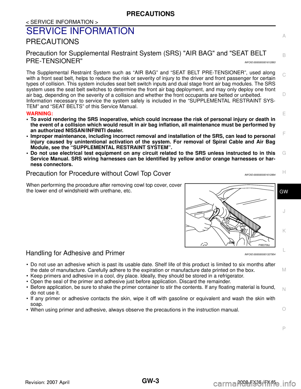
Precaution for Procedur e without Cowl Top CoverINFOID:0000000001612894
When performing the procedure after removing cowl top cover, cover
the lower end of windshield with urethane, etc.
Handling for Adhesive and PrimerINFOID:0000000001327954
Do not use an adhesive which is past its usable date. Shel f life of this product is limited to six months after
the date of manufacture. Carefully adhere to the ex piration or manufacture date printed on the box.
Keep primers and adhesive in a cool, dry place. I deally, they should be stored in a refrigerator.
Open the seal of the primer and adhesive just before application. Discard the remainder.
Before application, be sure to shake the primer container to stir the contents. If any floating material is found,
do not use it.
If any primer or adhesive contacts the skin, wipe it off with gasoline or equivalent and wash the skin with
soap.
When using primer and adhesive, always observe the precautions in the instruction manual.
PIIB3706J
3AA93ABC3ACD3AC03ACA3AC03AC63AC53A913A773A893A873A873A8E3A773A983AC73AC93AC03AC3
3A893A873A873A8F3A773A9D3AAF3A8A3A8C3A863A9D3AAF3A8B3A8C