2008 INFINITI FX35 wiring
[x] Cancel search: wiringPage 2429 of 3924
![INFINITI FX35 2008 Service Manual
VARIABLE INDUCTION AIR CONTROL SYSTEM (VIAS)
EC-1189
< SERVICE INFORMATION > [VK45DE]
C
D
E
F
G H
I
J
K L
M A
EC
NP
O
Wiring DiagramINFOID:0000000001327084
Specification data are reference values
an INFINITI FX35 2008 Service Manual
VARIABLE INDUCTION AIR CONTROL SYSTEM (VIAS)
EC-1189
< SERVICE INFORMATION > [VK45DE]
C
D
E
F
G H
I
J
K L
M A
EC
NP
O
Wiring DiagramINFOID:0000000001327084
Specification data are reference values
an](/manual-img/42/57017/w960_57017-2428.png)
VARIABLE INDUCTION AIR CONTROL SYSTEM (VIAS)
EC-1189
< SERVICE INFORMATION > [VK45DE]
C
D
E
F
G H
I
J
K L
M A
EC
NP
O
Wiring DiagramINFOID:0000000001327084
Specification data are reference values
and are measured between each terminal and ground.
CAUTION:
Do not use ECM ground terminals wh en measuring input/output voltage. Doing so may result in dam-
age to the ECM's transistor. Use a ground ot her than ECM terminals, such as the ground.
TBWM1370E
3AA93ABC3ACD3AC03ACA3AC03AC63AC53A913A773A893A873A873A8E3A773A983AC73AC93AC03AC3
3A893A873A873A8F3A773A9D3AAF3A8A3A8C3A863A9D3AAF3A8B3A8C
Page 2432 of 3924
![INFINITI FX35 2008 Service Manual
EC-1192
< SERVICE INFORMATION >[VK45DE]
VARIABLE INDUCTION AIR CONTROL SYSTEM (VIAS)
2. Disconnect VIAS control sol
enoid valve (1) harness connector.
- Vacuum tank (2)
3. Turn ignition switch ON.
4. INFINITI FX35 2008 Service Manual
EC-1192
< SERVICE INFORMATION >[VK45DE]
VARIABLE INDUCTION AIR CONTROL SYSTEM (VIAS)
2. Disconnect VIAS control sol
enoid valve (1) harness connector.
- Vacuum tank (2)
3. Turn ignition switch ON.
4.](/manual-img/42/57017/w960_57017-2431.png)
EC-1192
< SERVICE INFORMATION >[VK45DE]
VARIABLE INDUCTION AIR CONTROL SYSTEM (VIAS)
2. Disconnect VIAS control sol
enoid valve (1) harness connector.
- Vacuum tank (2)
3. Turn ignition switch ON.
4. Check voltage between VIAS control solenoid valve terminal 1 and ground with CONSULT-III or tester.
OK or NG
OK >> GO TO 8.
NG >> GO TO 7.
7.DETECT MALFUNCTIONING PART
Check the following.
Harness connectors E211, M41
Harness connectors M82, F102
IPDM E/R connector E7
10A fuse
Harness continuity between IPDM E/R and VIAS control solenoid valve
>> Repair open circuit or short to ground or short to power in harness or connectors.
8.CHECK VIAS CONTROL SOLENOID VALVE OUTP UT SIGNAL CIRCUIT FOR OPEN AND SHORT
1. Turn ignition switch OFF.
2. Disconnect ECM harness connector.
3. Check harness continuity between ECM terminal 29 and VIAS control solenoid valve terminal 2. Refer to Wiring Diagram.
4. Also check harness for short to ground and short to power.
OK or NG
OK >> GO TO 9.
NG >> Repair open circuit or short to ground or short to power in harness or connectors.
9.CHECK VIAS CONTROL SOLENOID VALVE
Refer to EC-1193, "
Component Inspection".
OK or NG
OK >> GO TO 10.
NG >> Replace VIAS control solenoid valve.
10.CHECK INTERMITTENT INCIDENT
Refer to EC-717
.
>> INSPECTION END
PBIB3236E
Voltage: Battery voltage
PBIB0173E
Continuity should exist.
3AA93ABC3ACD3AC03ACA3AC03AC63AC53A913A773A893A873A873A8E3A773A983AC73AC93AC03AC3
3A893A873A873A8F3A773A9D3AAF3A8A3A8C3A863A9D3AAF3A8B3A8C
Page 2434 of 3924
![INFINITI FX35 2008 Service Manual
EC-1194
< SERVICE INFORMATION >[VK45DE]
MIL AND DATA LINK CONNECTOR
MIL AND DATA LINK CONNECTOR
Wiring DiagramINFOID:0000000001327088
TBWM1367E
3AA93ABC3ACD3AC03ACA3AC03AC63AC53A913A773A893A873A873A8 INFINITI FX35 2008 Service Manual
EC-1194
< SERVICE INFORMATION >[VK45DE]
MIL AND DATA LINK CONNECTOR
MIL AND DATA LINK CONNECTOR
Wiring DiagramINFOID:0000000001327088
TBWM1367E
3AA93ABC3ACD3AC03ACA3AC03AC63AC53A913A773A893A873A873A8](/manual-img/42/57017/w960_57017-2433.png)
EC-1194
< SERVICE INFORMATION >[VK45DE]
MIL AND DATA LINK CONNECTOR
MIL AND DATA LINK CONNECTOR
Wiring DiagramINFOID:0000000001327088
TBWM1367E
3AA93ABC3ACD3AC03ACA3AC03AC63AC53A913A773A893A873A873A8E3A773A983AC73AC93AC03AC3
3A893A873A873A8F3A773A9D3AAF3A8A3A8C3A863A9D3AAF3A8B3A8C
Page 2440 of 3924

PRECAUTIONSEI-3
< SERVICE INFORMATION >
C
DE
F
G H
J
K L
M A
B
EI
N
O P
SERVICE INFORMATION
PRECAUTIONS
Precaution for Supplemental Restraint System (SRS) "AIR BAG" and "SEAT BELT
PRE-TENSIONER"
INFOID:0000000001612896
The Supplemental Restraint System such as “A IR BAG” and “SEAT BELT PRE-TENSIONER”, used along
with a front seat belt, helps to reduce the risk or severi ty of injury to the driver and front passenger for certain
types of collision. This system includes seat belt switch inputs and dual stage front air bag modules. The SRS
system uses the seat belt switches to determine the front air bag deployment, and may only deploy one front
air bag, depending on the severity of a collision and whether the front occupants are belted or unbelted.
Information necessary to service the system safely is included in the “SUPPLEMENTAL RESTRAINT SYS-
TEM” and “SEAT BELTS” of this Service Manual.
WARNING:
• To avoid rendering the SRS inoper ative, which could increase the risk of personal injury or death in
the event of a collision which would result in air bag inflation, all maintenance must be performed by
an authorized NISSAN/INFINITI dealer.
Improper maintenance, including in correct removal and installation of the SRS, can lead to personal
injury caused by unintentional act ivation of the system. For removal of Spiral Cable and Air Bag
Module, see the “SUPPLEMEN TAL RESTRAINT SYSTEM”.
Do not use electrical test equipm ent on any circuit related to the SRS unless instructed to in this
Service Manual. SRS wiring harnesses can be identi fied by yellow and/or orange harnesses or har-
ness connectors.
Precaution for Procedur e without Cowl Top CoverINFOID:0000000001612888
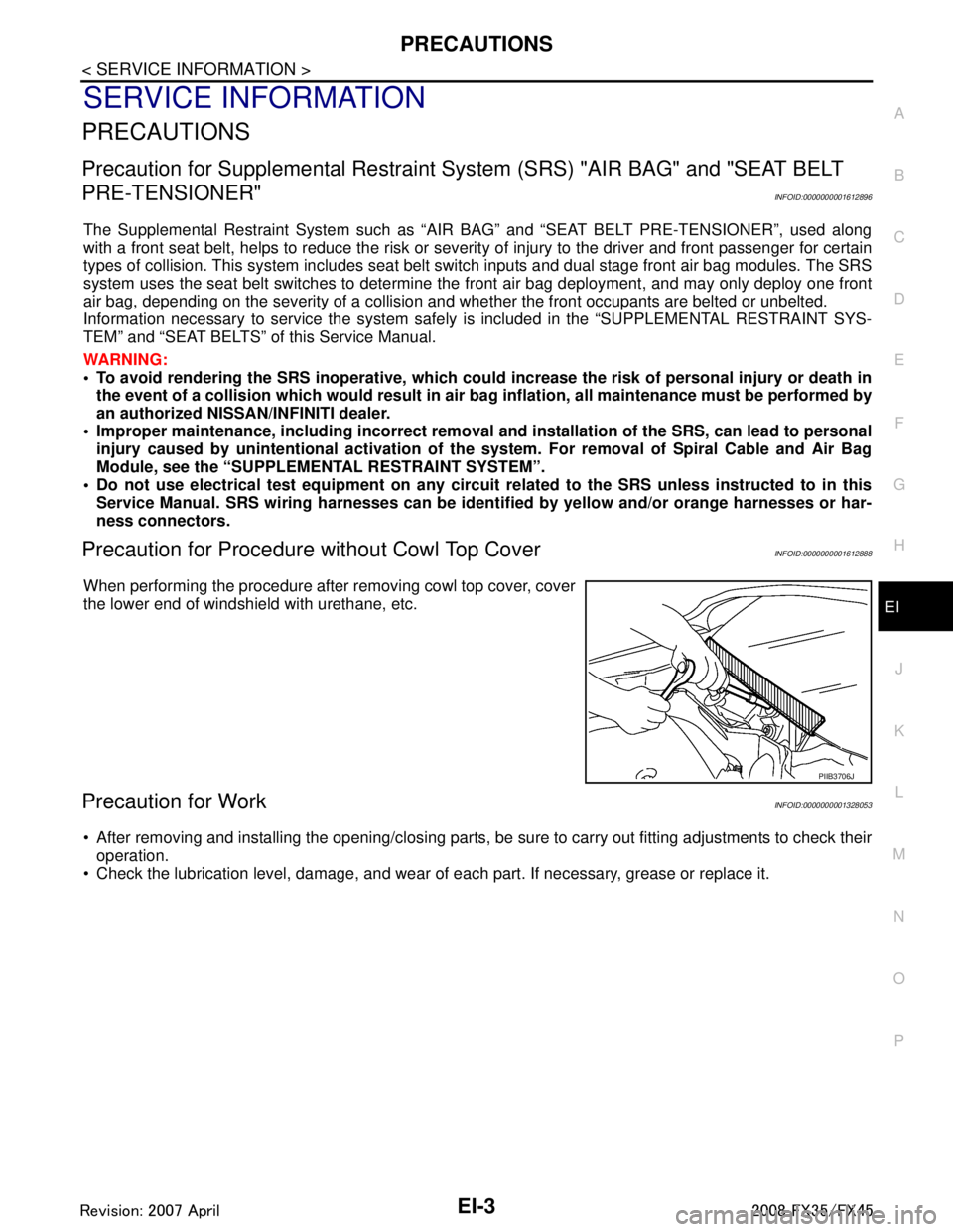
When performing the procedure after removing cowl top cover, cover
the lower end of windshield with urethane, etc.
Precaution for WorkINFOID:0000000001328053
After removing and installing the opening/closing parts, be sure to carry out fitting adjustments to check their
operation.
Check the lubrication level, damage, and wear of each part. If necessary, grease or replace it.
PIIB3706J
3AA93ABC3ACD3AC03ACA3AC03AC63AC53A913A773A893A873A873A8E3A773A983AC73AC93AC03AC3
3A893A873A873A8F3A773A9D3AAF3A8A3A8C3A863A9D3AAF3A8B3A8C
Page 2444 of 3924

SQUEAK AND RATTLE TROUBLE DIAGNOSESEI-7
< SERVICE INFORMATION >
C
DE
F
G H
J
K L
M A
B
EI
N
O P
Insulates where slight movement is present. Ideal for instrument panel applications.
SILICONE GREASE
Used in place of UHMW tape that will be visible or not fit.
Note: Will only last a few months.
SILICONE SPRAY
Use when grease cannot be applied.
DUCT TAPE
Use to eliminate movement.
CONFIRM THE REPAIR
Confirm that the cause of a noise is repaired by test driving the vehicle. Operate the vehicle under the same
conditions as when the noise originally occurred. Refer to the notes on the Diagnostic Worksheet.
Generic Squeak and Rattle TroubleshootingINFOID:0000000001328057
Refer to Table of Contents for specific component removal and installation information.
INSTRUMENT PANEL
Most incidents are caused by contact and movement between:
1. The cluster lid A and instrument panel
2. Acrylic lens and combination meter housing
3. Instrument panel to front pillar garnish
4. Instrument panel to windshield
5. Instrument panel mounting pins
6. Wiring harnesses behind the combination meter
7. A/C defroster duct and duct joint
These incidents can usually be located by tapping or moving the components to duplicate the noise or by
pressing on the components while driving to stop the noi se. Most of these incidents can be repaired by apply-
ing felt cloth tape or silicon spray (in hard to reach areas). Urethane pads can be used to insulate wiring har-
ness.
CAUTION:
Do not use silicone spray to isolate a squeak or ra ttle. If you saturate the area with silicone, you will
not be able to recheck the repair.
CENTER CONSOLE
Components to pay attention to include:
1. Shifter assembly cover to finisher
2. A/C control unit and cluster lid C
3. Wiring harnesses behind audio and A/C control unit
The instrument panel repair and isolation pr ocedures also apply to the center console.
DOORS
Pay attention to the:
1. Finisher and inner panel making a slapping noise
2. Inside handle escutcheon to door finisher
3. Wiring harnesses tapping
4. Door striker out of alignment causing a popping noise on starts and stops
Tapping or moving the components or pressing on them while driving to duplicate the conditions can isolate
many of these incidents. You can usually insulate the ar eas with felt cloth tape or insulator foam blocks from
the Nissan Squeak and Rattle Kit (J-43980) to repair the noise.
TRUNK
Trunk noises are often caused by a loose jack or loose items put into the trunk by the owner.
In addition look for:
1. Trunk lid dumpers out of adjustment
2. Trunk lid striker out of adjustment
3. The trunk lid torsion bars knocking together
4. A loose license plate or bracket
3AA93ABC3ACD3AC03ACA3AC03AC63AC53A913A773A893A873A873A8E3A773A983AC73AC93AC03AC3
3A893A873A873A8F3A773A9D3AAF3A8A3A8C3A863A9D3AAF3A8B3A8C
Page 2863 of 3924

GI-1
GENERAL INFORMATION
C
DE
F
G H
I
J
K L
M B
GI
SECTION GI
N
O P
CONTENTS
GENERAL INFORMATION
SERVICE INFORMATION .. ..........................2
PRECAUTIONS .............................................. .....2
Description .......................................................... ......2
Precaution for Supplemental Restraint System
(SRS) "AIR BAG" and "SEAT BELT PRE-TEN-
SIONER" ...................................................................
2
Precaution Necessary for Steering Wheel Rota-
tion After Battery Disconnect .....................................
2
Precaution for Procedure without Cowl Top Cover ......3
General Precaution ...................................................3
Precaution for Three Way Catalyst ...........................4
Precaution for Fuel (Unleaded Premium Gasoline
Recommended) .........................................................
5
Precaution for Fuel (Unleaded Premium Gasoline
Required) ..................................................................
5
Precaution for Multiport Fuel Injection System or
Engine Control System .............................................
5
Precaution for Hoses .................................................5
Precaution for Engine Oils ........................................6
Precaution for the Environment .................................7
Precaution for Air Conditioning .................................7
HOW TO USE THIS MANUAL ............................8
Description .......................................................... ......8
Terms ........................................................................8
Units ..........................................................................8
Contents ....................................................................8
Component ................................................................8
How to Follow Trouble Diagnosis ..............................9
How to Read Wiring Diagram ..................................13
Abbreviations ..........................................................20
SERVICE INFORMATION FOR ELECTRICAL
INCIDENT ...........................................................
22
How to Check Terminal ....................................... ....22
How to Perform Efficient Diagnosis for an Electri-
cal Incident .......................................................... ....
25
Control Units and Electrical Parts ............................32
CONSULT-III/GST CHECKING SYSTEM .........34
Description ...............................................................34
CONSULT-III Function and System Application*1 ....34
CONSULT-III/GST Data Link Connector (DLC)
Circuit ......................................................................
35
Wiring Diagram - CONSULT-III/GST CHECKING
SYSTEM - ................................................................
36
LIFTING POINT .................................................37
Commercial Service Tool ........................................37
Garage Jack and Safety Stand ................................37
2-Pole Lift ................................................................38
Board-On Lift ...........................................................38
TOW TRUCK TOWING .....................................40
Tow Truck Towing ...................................................40
Vehicle Recovery (Freeing a Stuck Vehicle) ...........41
TIGHTENING TORQUE OF STANDARD
BOLTS ...............................................................
43
Tightening Torque Table .........................................43
RECOMMENDED CHEMICAL PRODUCTS
AND SEALANTS ...............................................
44
Recommended Chemical Product and Sealant .......44
IDENTIFICATION INFORMATION ....................45
Model Variation ........................................................45
Dimensions ..............................................................47
Wheels & Tires ........................................................47
TERMINOLOGY ................................................48
SAE J1930 Terminology List ...................................48
3AA93ABC3ACD3AC03ACA3AC03AC63AC53A913A773A893A873A873A8E3A773A983AC73AC93AC03AC3
3A893A873A873A8F3A773A9D3AAF3A8A3A8C3A863A9D3AAF3A8B3A8C
Page 2864 of 3924

GI-2
< SERVICE INFORMATION >
PRECAUTIONS
SERVICE INFORMATION
PRECAUTIONS
DescriptionINFOID:0000000001325649
Observe the following precautions to ensure safe and proper servicing. These precautions are not
described in each individual section.
Precaution for Supplemental Restraint S ystem (SRS) "AIR BAG" and "SEAT BELT
PRE-TENSIONER"
INFOID:0000000001612904
The Supplemental Restraint System such as “A IR BAG” and “SEAT BELT PRE-TENSIONER”, used along
with a front seat belt, helps to reduce the risk or severi ty of injury to the driver and front passenger for certain
types of collision. This system includes seat belt switch inputs and dual stage front air bag modules. The SRS
system uses the seat belt switches to determine the front air bag deployment, and may only deploy one front
air bag, depending on the severity of a collision and w hether the front occupants are belted or unbelted.
Information necessary to service the system safely is included in the “SUPPLEMENTAL RESTRAINT SYS-
TEM” and “SEAT BELTS” of this Service Manual.
WARNING:
• To avoid rendering the SRS inopera tive, which could increase the risk of personal injury or death in
the event of a collision which would result in air bag inflation, all maintenance must be performed by
an authorized NISS AN/INFINITI dealer.
Improper maintenance, including in correct removal and installation of the SRS, can lead to personal
injury caused by unintent ional activation of the system. For re moval of Spiral Cable and Air Bag
Module, see the “SUPPLEMEN TAL RESTRAINT SYSTEM”.
Do not use electrical test equipmen t on any circuit related to the SRS unless instructed to in this
Service Manual. SRS wiring harnesses can be identi fied by yellow and/or orange harnesses or har-
ness connectors.
Precaution Necessary for Steering W heel Rotation After Battery Disconnect
INFOID:0000000001612934
NOTE:
This Procedure is applied only to models with In telligent Key system and NVIS/IVIS (NISSAN/INFINITI
VEHICLE IMMOBILIZER SYSTEM - NATS).
Remove and install all control units after disconnecting both battery cables with the ignition knob in the ″LOCK ″ position.
Always use CONSULT-III to perform self-diagnosis as a part of each function inspection after finishing work.
If DTC is detected, perform trouble diagnosis according to self-diagnostic results.
For models equipped with the Intelligent Key system and NVIS /IVIS, an electrically controlled steering lock
mechanism is adopted on the key cylinder.
For this reason, if the battery is disconnected or if the battery is discharged, the steering wheel will lock and
steering wheel rotation will become impossible.
If steering wheel rotation is required when battery pow er is interrupted, follow the procedure below before
starting the repair operation.
OPERATION PROCEDURE
1. Connect both battery cables. NOTE:
Supply power using jumper cables if battery is discharged.
2. Use the Intelligent Key or mechanical key to turn the ignition switch to the ″ACC ″ position. At this time, the
steering lock will be released.
3. Disconnect both battery cables. The steering lock will remain released and the steering wheel can be
rotated.
4. Perform the necessary repair operation.
5. When the repair work is completed, return the ignition switch to the ″LOCK ″ position before connecting
the battery cables. (At this time, the steering lock mechanism will engage.)
6. Perform a self-diagnosis check of all control units using CONSULT-III.
3AA93ABC3ACD3AC03ACA3AC03AC63AC53A913A773A893A873A873A8E3A773A983AC73AC93AC03AC3
3A893A873A873A8F3A773A9D3AAF3A8A3A8C3A863A9D3AAF3A8B3A8C
Page 2872 of 3924

GI-10
< SERVICE INFORMATION >
HOW TO USE THIS MANUAL
3.Refer to Component Parts and Harness Connector Location for the Systems described in each
section for identifi cation/location of componen ts and harness connectors.
4. Refer to the Circuit Diagra m for quick pinpoint check.
If you need to check circuit continuity between harness connectors in more detail, such as when a
sub-harness is used, refer to Wiring Diagram in each individual section and Harness Layout in PG
section for identificatio n of harness connectors.
5. When checking circuit continuity, ignition switch should be OFF.
6. Before checking voltage at co nnectors, check battery voltage.
7. After accomplishing the Diagnost ic Procedures and Electrical Components Inspection, make sure
that all harness connectors ar e reconnected as they were.
HOW TO FOLLOW TEST GROUPS IN TROUBLE DIAGNOSES
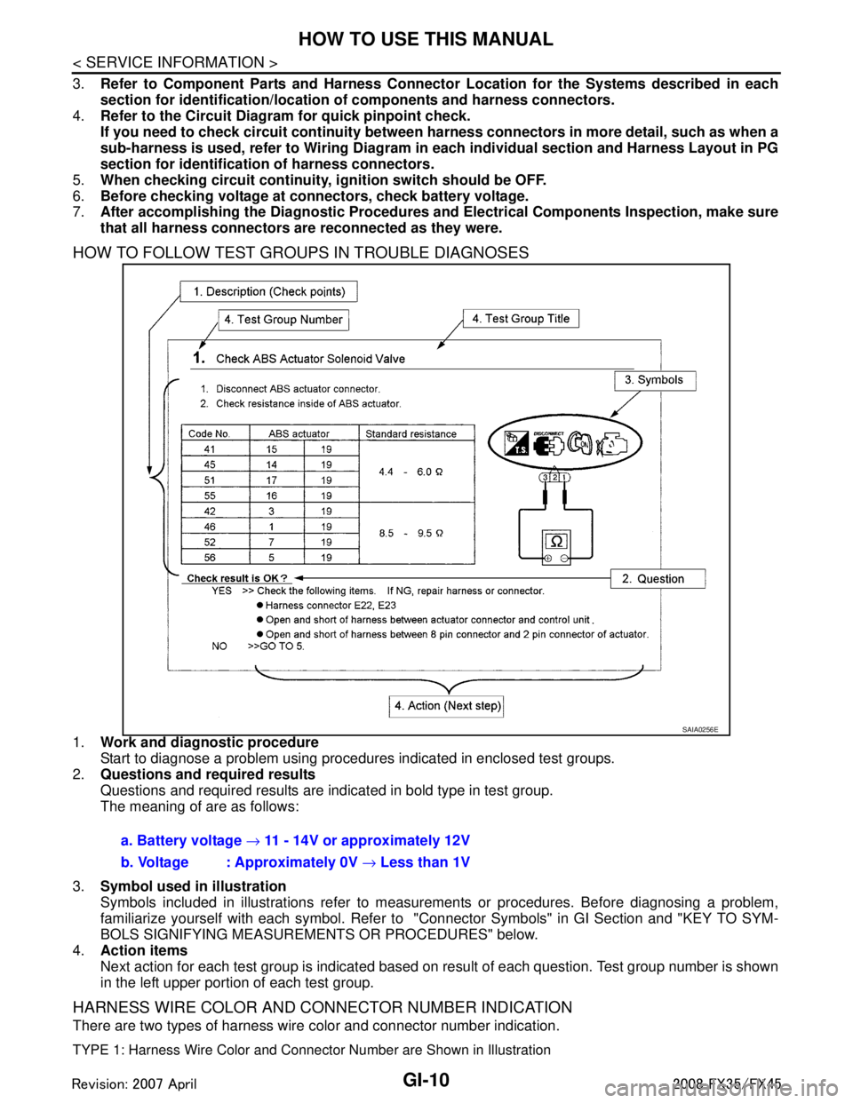
1.Work and diagnostic procedure
Start to diagnose a problem using procedures indicated in enclosed test groups.
2. Questions and required results
Questions and required results are indicated in bold type in test group.
The meaning of are as follows:
3. Symbol used in illustration
Symbols included in illustrations refer to measur ements or procedures. Before diagnosing a problem,
familiarize yourself with each symbol. Refer to "Connector Symbols" in GI Section and "KEY TO SYM-
BOLS SIGNIFYING MEASUREME NTS OR PROCEDURES" below.
4. Action items
Next action for each test group is indicated based on result of each question. Test group number is shown
in the left upper portion of each test group.
HARNESS WIRE COLOR AND CONNECTOR NUMBER INDICATION
There are two types of harness wire color and connector number indication.
TYPE 1: Harness Wire Color and Connec tor Number are Shown in Illustration
SAIA0256E
a. Battery voltage → 11 - 14V or approximately 12V
b. Voltage : Approximately 0V → Less than 1V
3AA93ABC3ACD3AC03ACA3AC03AC63AC53A913A773A893A873A873A8E3A773A983AC73AC93AC03AC3
3A893A873A873A8F3A773A9D3AAF3A8A3A8C3A863A9D3AAF3A8B3A8C