2008 INFINITI FX35 ECU
[x] Cancel search: ECUPage 3520 of 3924
SQUEAK AND RATTLE TROUBLE DIAGNOSESRF-5
< SERVICE INFORMATION >
C
DE
F
G H
J
K L
M A
B
RF
N
O P
If the noise can be duplicated easily during the test drive, to help identify the source of the noise, try to dupli-
cate the noise with the vehicle stopped by doing one or all of the following:
1) Close a door.
2) Tap or push/pull around the area where the noise appears to be coming from.
3) Rev the engine.
4) Use a floor jack to recreate vehicle “twist”.
5) At idle, apply engine load (electrical load, half- clutch on M/T model, drive position on A/T model).
6) Raise the vehicle on a hoist and hit a tire with a rubber hammer.
Drive the vehicle and attempt to duplicate the conditions the customer states exist when the noise occurs.
If it is difficult to duplicate the noise, drive the vehicle slowly on an undulating or rough road to stress the vehicle body.
CHECK RELATED SERVICE BULLETINS
After verifying the customer concern or symptom, che ck ASIST for Technical Service Bulletins (TSBs) related
to that concern or symptom.
If a TSB relates to the symptom, follow the procedure to repair the noise.
LOCATE THE NOISE AND IDENTIFY THE ROOT CAUSE
1. Narrow down the noise to a general area. To help pinpoint the source of the noise, use a listening tool (Chassis Ear: J39570, Engine Ea r and mechanics stethoscope).
2. Narrow down the noise to a more specific area and identify the cause of the noise by:
removing the components in the area that you suspect the noise is coming from. Do not use too much force when removing clips and fasteners, otherwise clips and fastener can be broken
or lost during the repair, resulting in the creation of new noise.
tapping or pushing/pulling the component that you suspect is causing the noise.
Do not tap or push/pull the component with excessive force, otherwise the noise will be eliminated only tem-
porarily.
feeling for a vibration with your hand by touching the component(s) that you suspect is (are) causing the
noise.
placing a piece of paper between components that you suspect are causing the noise.
looking for loose components and contact marks. Refer to RF-6, "
Generic Squeak and Rattle Troubleshooting".
REPAIR THE CAUSE
If the cause is a loose component, tighten the component securely.
If the cause is insufficient clearance between components:
- separate components by repositioning or loos ening and retightening the component, if possible.
- insulate components with a suitable insulator such as urethane pads, foam blocks, felt cloth tape or urethane tape. A Nissan Squeak and Rattle Kit (J43980) is available through your authorized Nissan Parts Depart-
ment.
CAUTION:
Do not use excessive force as many components are constructed of plastic and may be damaged.
NOTE:
Always check with the Parts Department for the latest parts information.
The following materials are contained in the Nissan Squeak and Rattle Kit (J43980). Each item can be ordered
separately as needed.
URETHANE PADS [1.5 mm (0.059 in) thick]
Insulates connectors, harness, etc.
76268-9E005: 100 × 135 mm (3.94 × 5.31 in)/76884-71L01: 60 × 85 mm (2.36 × 3.35 in)/76884-71L02: 15 ×
25 mm (0.59 × 0.98 in)
INSULATOR (Foam blocks)
Insulates components from contact.Can be used to fill space behind a panel.
73982-9E000: 45 mm (1.77 in) thick, 50 × 50 mm (1.97 × 1.97 in)/73982-50Y00: 10 mm (0.39 in) thick, 50
× 50 mm (1.97 × 1.97 in)
INSULATOR (Light foam block)
80845-71L00: 30 mm (1.18 in) thick, 30 × 50 mm (1.18 × 1.97 in)
FELT CLOTHTAPE
Used to insulate where movement does not occur. Ideal for instrument panel applications.
68370-4B000: 15 × 25 mm (0.59 × 0.98 in) pad/68239-13E00: 5 mm (0.20 in) wide tape roll
The following materials, not found in the kit, can also be used to repair squeaks and rattles.
UHMW(TEFLON) TAPE
3AA93ABC3ACD3AC03ACA3AC03AC63AC53A913A773A893A873A873A8E3A773A983AC73AC93AC03AC3
3A893A873A873A8F3A773A9D3AAF3A8A3A8C3A863A9D3AAF3A8B3A8C
Page 3522 of 3924
SQUEAK AND RATTLE TROUBLE DIAGNOSESRF-7
< SERVICE INFORMATION >
C
DE
F
G H
J
K L
M A
B
RF
N
O P
Most of these incidents can be repaired by adjusting, se curing or insulating the item(s) or component(s) caus-
ing the noise.
SUNROOF/HEADLINING
Noises in the sunroof/headlining area can often be traced to one of the following:
1. Sunroof lid, rail, linkage or seals making a rattle or light knocking noise
2. Sunvisor shaft shaking in the holder
3. Front or rear windshield touching headlining and squeaking
Again, pressing on the components to stop the noise while duplicating the conditions can isolate most of these
incidents. Repairs usually consist of insulating with felt cloth tape.
SEATS
When isolating seat noise it's important to note the pos ition the seat is in and the load placed on the seat when
the noise is present. These conditions should be duplic ated when verifying and isolating the cause of the
noise.
Cause of seat noise include:
1. Headrest rods and holder
2. A squeak between the seat pad cushion and frame
3. Rear seatback lock and bracket
These noises can be isolated by moving or pressing on the suspected components while duplicating the con-
ditions under which the noise occurs. Most of thes e incidents can be repaired by repositioning the component
or applying urethane tape to the contact area.
UNDERHOOD
Some interior noise may be caused by components under the hood or on the engine wall. The noise is then
transmitted into the passenger compartment.
Causes of transmitted underhood noise include:
1. Any component mounted to the engine wall
2. Components that pass through the engine wall
3. Engine wall mounts and connectors
4. Loose radiator mounting pins
5. Hood bumpers out of adjustment
6. Hood striker out of adjustment
These noises can be difficult to isolate since they cannot be reached from the interior of the vehicle. The best
method is to secure, move or insulate one component at a time and test drive the vehicle. Also, engine RPM
or load can be changed to isolate the noise. Repairs c an usually be made by moving, adjusting, securing, or
insulating the component causing the noise.
3AA93ABC3ACD3AC03ACA3AC03AC63AC53A913A773A893A873A873A8E3A773A983AC73AC93AC03AC3
3A893A873A873A8F3A773A9D3AAF3A8A3A8C3A863A9D3AAF3A8B3A8C
Page 3541 of 3924
RF-26
< SERVICE INFORMATION >
SUNROOF
Removal
NOTE:
Detaching is possible even with the sunshade attached on the vehicle.
1. Remove the headlining. Refer to EI-43, "
Component Parts Location".
2. Remove sunshade stopper.
3. The protection tape is pasted to the sunshade knob.
4. Pull sunshade out of the rear end of the sunroof frame, and remove it from the frame.
CAUTION:
Do not damage the sunshade and sunshade knob while lift-
ing up a little.
Installation
Install in the reverse order of removal.
WIND DEFLECTOR
Removal
NOTE:
Detaching is possible even with the wind deflector attached on the vehicle.
1. The sunroof is opened.
2. Remove spring hinge screws, then remove hinge from theframe.
3. Remove the wind deflector.
Installation
Install in the reverse order of removal.
SUNROOF MOTOR ASSEMBLY
Removal
1. Remove headlining. Refer to EI-43, "Component Parts Loca-
tion".
2. Remove motor mounting screw.
3. Disconnect harness connector from sunroof motor assembly, then remove sunroof motor assembly.
CAUTION:
When removing the sunroof motor assembly, be sure that
the sunroof is in the fully closed position.
Do not run the removed sunroof motor assembly as a sin- gle unit.
Installation
Move the sunroof motor assembly laterally little by lit tle so that the gear is completely engaged into the wire on
the sunroof unit assembly and the mounting surface bec omes parallel. Then secure the sunroof motor
assembly with screws.
CAUTION:
PIIA5064E
PIIA3510E
PIIA6189E
3AA93ABC3ACD3AC03ACA3AC03AC63AC53A913A773A893A873A873A8E3A773A983AC73AC93AC03AC3
3A893A873A873A8F3A773A9D3AAF3A8A3A8C3A863A9D3AAF3A8B3A8C
Page 3559 of 3924
REAR FINAL DRIVE ASSEMBLYRFD-17
< SERVICE INFORMATION >
CEF
G H
I
J
K L
M A
B
RFD
N
O P
8. Remove the mounting bolts and nuts connecting to the suspen- sion member, and remove rear final drive assembly with a power
tool.
CAUTION:
Secure rear final drive assembly to a suitable jack while
removing it.
INSTALLATION
Note the following, and installation is in the reverse order of removal.
Refer to "COMPONENTS" about each tightening torque.
When installing breather hoses (1), refer to the figure.CAUTION:
Make sure there are no pinched or restricted areas on the
breather hose caused by bending or winding when installing
it.
- For installation, the vehicle side end shall be inserted to suspen- sion member (2). Install metal connector (3) side of this hose to
rear cover by inserting it with aiming painted marking to the front of
vehicle.
When oil leaks while removing final drive assembly, check oil level
after the installation. Refer to RFD-9, "
Checking Differential Gear
Oil".
Disassembly and AssemblyINFOID:0000000001327500
COMPONENTS
SDIA1969J
SDIA1970J
PDIA0754E
3AA93ABC3ACD3AC03ACA3AC03AC63AC53A913A773A893A873A873A8E3A773A983AC73AC93AC03AC3
3A893A873A873A8F3A773A9D3AAF3A8A3A8C3A863A9D3AAF3A8B3A8C
Page 3560 of 3924
RFD-18
< SERVICE INFORMATION >
REAR FINAL DRIVE ASSEMBLY
ASSEMBLY INSPECTION AND ADJUSTMENT
Before inspection and adjustment, drain gear oil.
Total Preload Torque
1. Secure final drive assembly onto an attachment.
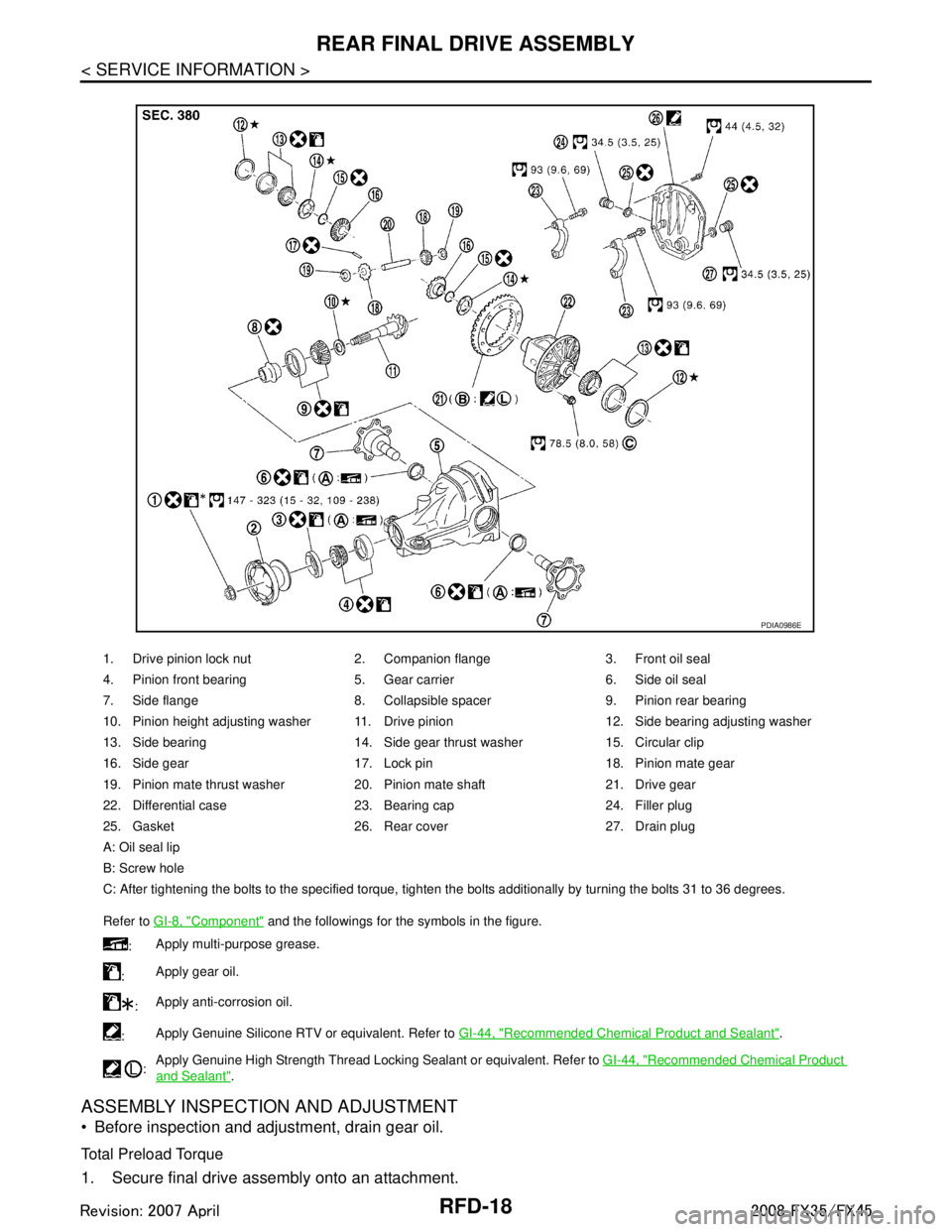
1. Drive pinion lock nut 2. Companion flange 3. Front oil seal
4. Pinion front bearing 5. Gear carrier 6. Side oil seal
7. Side flange 8. Collapsible spacer 9. Pinion rear bearing
10. Pinion height adjusting washer 11. Drive pinion 12. Side bearing adjusting washer
13. Side bearing 14. Side gear thrust washer 15. Circular clip
16. Side gear 17. Lock pin 18. Pinion mate gear
19. Pinion mate thrust washer 20. Pinion mate shaft 21. Drive gear
22. Differential case 23. Bearing cap 24. Filler plug
25. Gasket 26. Rear cover 27. Drain plug
A: Oil seal lip
B: Screw hole
C: After tightening the bolts to the specified torque, tighten the bolts additionally by turning the bolts 31 to 36 degrees.
Refer to GI-8, "
Component" and the followings for the symbols in the figure.
: Apply multi-purpose grease.
: Apply gear oil.
: Apply anti-corrosion oil.
: Apply Genuine Silicone RTV or equivalent. Refer to
GI-44, "
Recommended Chemical Product and Sealant".
: Apply Genuine High Strength Thread Locking Sealant or equivalent. Refer to
GI-44, "
Recommended Chemical Product
and Sealant".
PDIA0986E
3AA93ABC3ACD3AC03ACA3AC03AC63AC53A913A773A893A873A873A8E3A773A983AC73AC93AC03AC3
3A893A873A873A8F3A773A9D3AAF3A8A3A8C3A863A9D3AAF3A8B3A8C
Page 3571 of 3924
REAR FINAL DRIVE ASSEMBLYRFD-29
< SERVICE INFORMATION >
CEF
G H
I
J
K L
M A
B
RFD
N
O P
1. Make sure all parts are clean and that the bearings are well lubricated.
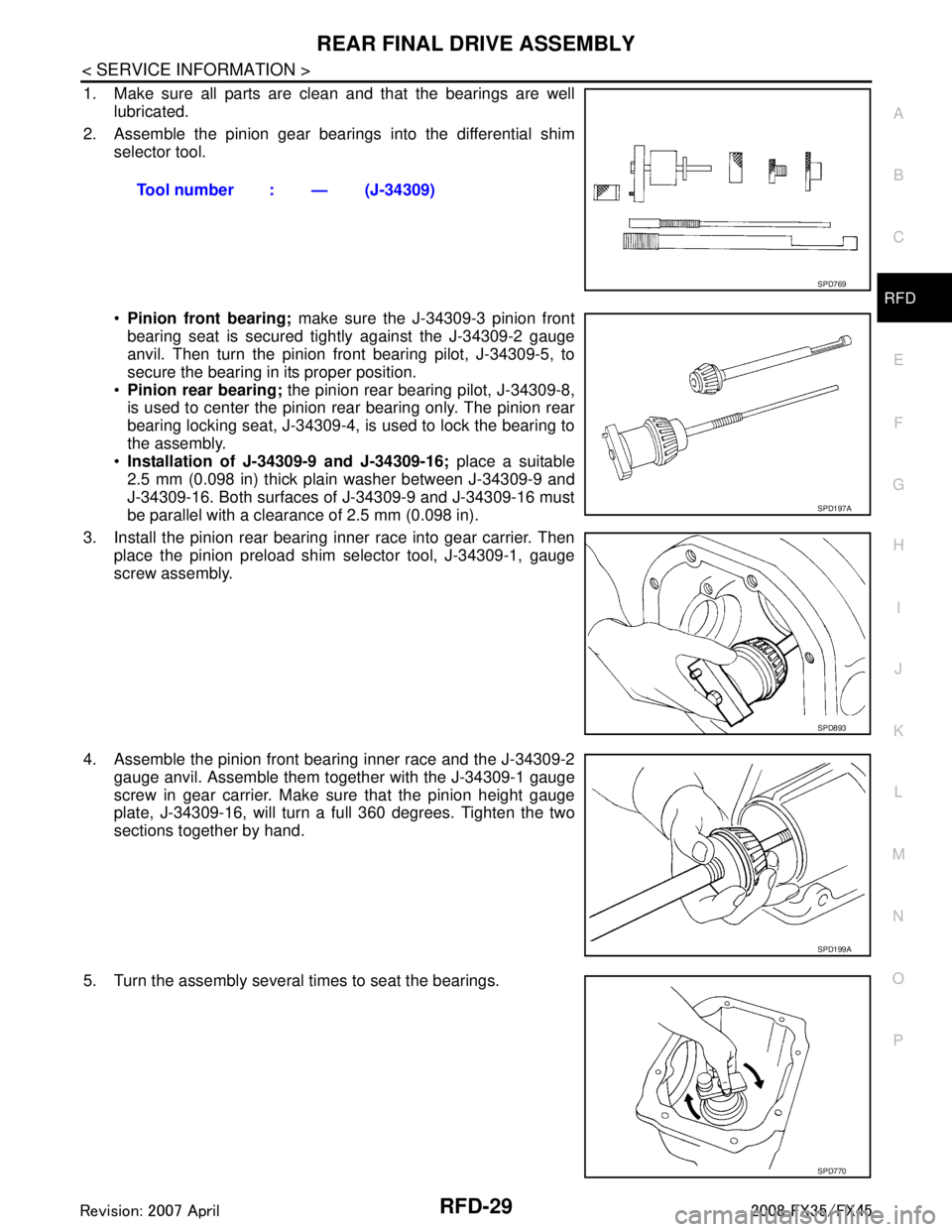
2. Assemble the pinion gear beari ngs into the differential shim
selector tool.
Pinion front bearing; make sure the J-34309-3 pinion front
bearing seat is secured tightly against the J-34309-2 gauge
anvil. Then turn the pinion front bearing pilot, J-34309-5, to
secure the bearing in its proper position.
Pinion rear bearing; the pinion rear bearing pilot, J-34309-8,
is used to center the pinion rear bearing only. The pinion rear
bearing locking seat, J-34309-4, is used to lock the bearing to
the assembly.
Installation of J-34309-9 and J-34309-16; place a suitable
2.5 mm (0.098 in) thick plain washer between J-34309-9 and
J-34309-16. Both surfaces of J-34309-9 and J-34309-16 must
be parallel with a clearance of 2.5 mm (0.098 in).
3. Install the pinion rear bearing inner race into gear carrier. Then place the pinion preload shim selector tool, J-34309-1, gauge
screw assembly.
4. Assemble the pinion front bearing inner race and the J-34309-2 gauge anvil. Assemble them together with the J-34309-1 gauge
screw in gear carrier. Make sure that the pinion height gauge
plate, J-34309-16, will turn a full 360 degrees. Tighten the two
sections together by hand.
5. Turn the assembly several times to seat the bearings. Tool number : — (J-34309)
SPD769
SPD197A
SPD893
SPD199A
SPD770
3AA93ABC3ACD3AC03ACA3AC03AC63AC53A913A773A893A873A873A8E3A773A983AC73AC93AC03AC3
3A893A873A873A8F3A773A9D3AAF3A8A3A8C3A863A9D3AAF3A8B3A8C
Page 3605 of 3924
SB-6
< SERVICE INFORMATION >
SEAT BELTS
6. Remove the outer side retractor and center seat retractor mounting anchor bolts.
7. Remove the seat belt assembly.
INSTALLATION OF REAR SEAT BELT RETRACTOR
Install in the reverse order of removal.
Seat Belt InspectionINFOID:0000000001327737
AFTER A COLLISION
WARNING:
Inspect all seat belt assemblies in cluding retractors and attaching hardware after any collision.
NISSAN recommends that all seat belt assemblies in use during a collision be replaced unless the col-
lision was minor and the belts show no damage and continue to operate properly. Failure to do so
could result in serious personal injury in an acci dent. Seat belt assemblies not in use during a colli-
sion should also be replaced if ei ther damage or improper operation is noted. Seat belt pre-tensioners
should be replaced even if the seat belts are not in use during a frontal collision in which the air bags
are deployed.
Replace any seat belt assembly (including anchor bolts) if:
The seat belt was in use at the time of a collision (except for minor collisions and the belts, retractors and
buckles show no damage and continue to operate properly).
The seat belt was damaged in an accident. (i.e. torn webbing, bent retractor or guide).
The seat belt attaching point was damaged in an acci dent. Inspect the seat belt attaching area for damage
or distortion and repair as necessary before installing a new seat belt assembly.
Anchor bolts are deformed or worn out.
The front seat belt pre-tensioner should be replaced even if the seat belts are not in use during the collision
in which the air bags are deployed.
PRELIMINARY CHECK
1. Check the seat belt warning lamp/chime for proper operation as follows:
a. Turn ignition switch ON. The seat belt warning lamp should illuminate. Also, the seat belt warning chime should sound for about six seconds.
b. Fasten driver's seat belt. The seat belt warni ng lamp should go out and the chime (if sounding) should
stop.
2. If the air bag warning lamp is blinking, perform self-diagnosis using CONSULT-II, and air bag warning lamp. Refer to SRS-23, "
SRS Operation Check".
3. Make sure that the seat belt retractor, seat belt anchor and buckle bolts are securely attached.
4. Check the shoulder seat belt guide and shoulder belt height adjuster for\
front seats. Ensure guide swivels freely and that webbing lays flat and does not bind in guide. Ensure height adjuster operates properly and
holds securely.
5. Check retractor operation:
a. Fully extend the seat belt webbing and c heck for twists, tears or other damage.
b. Allow the seat belt to retract. Ensure that webbing returns smoothly and completely into the retractor. If
the seat belt does not return smoothly, wipe the insi de of the loops with a clean paper cloth, because dirt
built up in the loops of the upper anchors can cause the seat belts to retract slowly.
c. Fasten the seat belt. Check the seat belt returns sm oothly and completely to the retractor. If the webbing
does not return smoothly, the cause may be an accumulation of dust or dirt. Use the “SEAT BELT TAPE
SET” and perform the following steps.
Inspect the front seat belt through-anchor:
1. Pull the seat belt out to a length of 500 mm (19.69 in) or more.
2. Use a clip or other device to the fix the seat belt at the center pillar webbing opening.
3. Pass a thin wire through the through-anchor webbing opening. Hold both ends of the wire and pull taut while moving it up and down several times along the webbing opening surface to remove dirt.
4. Any dirt that cannot be removed with the wir e can be removed by cleaning the opening with a clean
cloth.
5. Apply tape at the point where the webbi ng contacts the through-anchor webbing opening.
NOTE:
Apply the tape so that there is no looseness or wrinkling.
6. Remove the clip fixing the seat belt and ensure that the webbing returns smoothly.
3AA93ABC3ACD3AC03ACA3AC03AC63AC53A913A773A893A873A873A8E3A773A983AC73AC93AC03AC3
3A893A873A873A8F3A773A9D3AAF3A8A3A8C3A863A9D3AAF3A8B3A8C
Page 3646 of 3924
SQUEAK AND RATTLE TROUBLE DIAGNOSESSE-7
< SERVICE INFORMATION >
C
DE
F
G H
J
K L
M A
B
SE
N
O P
If the noise can be duplicated easily during the test drive, to help identify the source of the noise, try to dupli-
cate the noise with the vehicle stopped by doing one or all of the following:
1) Close a door.
2) Tap or push/pull around the area where the noise appears to be coming from.
3) Rev the engine.
4) Use a floor jack to recreate vehicle “twist”.
5) At idle, apply engine load (electrical load, half- clutch on M/T model, drive position on A/T model).
6) Raise the vehicle on a hoist and hit a tire with a rubber hammer.
Drive the vehicle and attempt to duplicate the conditions the customer states exist when the noise occurs.
If it is difficult to duplicate the noise, drive the vehicle slowly on an undulating or rough road to stress the vehicle body.
CHECK RELATED SERVICE BULLETINS
After verifying the customer concern or symptom, che ck ASIST for Technical Service Bulletins (TSBs) related
to that concern or symptom.
If a TSB relates to the symptom, follow the procedure to repair the noise.
LOCATE THE NOISE AND IDENTIFY THE ROOT CAUSE
1. Narrow down the noise to a general area. To help pinpoint the source of the noise, use a listening tool (Chassis Ear: J-39570,Engine Ear and mechanics stethoscope).
2. Narrow down the noise to a more specific area and identify the cause of the noise by:
removing the components in the area that you suspect the noise is coming from. Do not use too much force when removing clips and fasteners, otherwise clips and fastener can be broken
or lost during the repair, resulting in the creation of new noise.
tapping or pushing/pulling the component that you suspect is causing the noise.
Do not tap or push/pull the component with excessive force, otherwise the noise will be eliminated only tem-
porarily.
feeling for a vibration with your hand by touching the component(s) that you suspect is (are) causing the
noise.
placing a piece of paper between components that you suspect are causing the noise.
looking for loose components and contact marks. Refer to SE-8, "
Generic Squeak and Rattle Troubleshooting".
REPAIR THE CAUSE
If the cause is a loose component, tighten the component securely.
If the cause is insufficient clearance between components:
- separate components by repositioning or loos ening and retightening the component, if possible.
- insulate components with a suitable insulator such as urethane pads, foam blocks, felt cloth tape or urethane tape. A Nissan Squeak and Rattle Kit (J-43980) is av ailable through your authorized Nissan Parts Depart-
ment.
CAUTION:
Do not use excessive force as many components are constructed of plastic and may be damaged.
NOTE:
Always check with the Parts Department for the latest parts information.
The following materials are contained in the Niss an Squeak and Rattle Kit (J-43980). Each item can be
ordered separately as needed.
URETHANE PADS [1.5 mm (0.059 in) thick]
Insulates connectors, harness, etc.
76268-9E005: 100 × 135 mm (3.94 × 5.31 in)/76884-71L01: 60 × 85 mm (2.36 × 3.35 in)/76884-71L02:15 ×
25 mm (0.59 × 0.98 in)
INSULATOR (Foam blocks)
Insulates components from contact. Can be used to fill space behind a panel.
73982-9E000: 45 mm (1.77 in) thick, 50 × 50 mm (1.97 × 1.97 in)/73982-50Y00: 10 mm (0.39 in) thick, 50
× 50 mm (1.97 × 1.97 in)
INSULATOR (Light foam block)
80845-71L00: 30 mm (1.18 in) thick, 30 × 50 mm (1.18 × 1.97 in)
FELT CLOTHTAPE
Used to insulate where movement does not occur. Ideal for instrument panel applications.
68370-4B000: 15 × 25 mm (0.59 × 0.98 in) pad/68239-13E00: 5 mm (0.20 in) wide tape roll The following
materials, not found in the kit, can also be used to repair squeaks and rattles.
UHMW(TEFLON) TAPE
3AA93ABC3ACD3AC03ACA3AC03AC63AC53A913A773A893A873A873A8E3A773A983AC73AC93AC03AC3
3A893A873A873A8F3A773A9D3AAF3A8A3A8C3A863A9D3AAF3A8B3A8C