2008 INFINITI FX35 ECU
[x] Cancel search: ECUPage 3648 of 3924

SQUEAK AND RATTLE TROUBLE DIAGNOSESSE-9
< SERVICE INFORMATION >
C
DE
F
G H
J
K L
M A
B
SE
N
O P
Most of these incidents can be repaired by adjusting, se curing or insulating the item(s) or component(s) caus-
ing the noise.
SUNROOF/HEADLINING
Noises in the sunroof/headlining area can often be traced to one of the following:
1. Sunroof lid, rail, linkage or seals making a rattle or light knocking noise
2. Sun-visor shaft shaking in the holder
3. Front or rear windshield touching headlining and squeaking
Again, pressing on the components to stop the noise while duplicating the conditions can isolate most of these
incidents. Repairs usually consist of insulating with felt cloth tape.
SEATS
When isolating seat noise it's important to note the pos ition the seat is in and the load placed on the seat when
the noise is present. These conditions should be duplic ated when verifying and isolating the cause of the
noise.
Cause of seat noise include:
1. Headrest rods and holder
2. A squeak between the seat pad cushion and frame
3. The rear seatback lock and bracket
These noises can be isolated by moving or pressing on the suspected components while duplicating the con-
ditions under which the noise occurs. Most of thes e incidents can be repaired by repositioning the component
or applying urethane tape to the contact area.
UNDERHOOD
Some interior noise may be caused by components under the hood or on the engine wall. The noise is then
transmitted into the passenger compartment.
Causes of transmitted under-hood noise include:
1. Any component mounted to the engine wall
2. Components that pass through the engine wall
3. Engine wall mounts and connectors
4. Loose radiator mounting pins
5. Hood bumpers out of adjustment
6. Hood striker out of adjustment
These noises can be difficult to isolate since they cannot be reached from the interior of the vehicle. The best
method is to secure, move or insulate one component at a time and test drive the vehicle. Also, engine RPM
or load can be changed to isolate the noise. Repairs c an usually be made by moving, adjusting, securing, or
insulating the component causing the noise.
3AA93ABC3ACD3AC03ACA3AC03AC63AC53A913A773A893A873A873A8E3A773A983AC73AC93AC03AC3
3A893A873A873A8F3A773A9D3AAF3A8A3A8C3A863A9D3AAF3A8B3A8C
Page 3731 of 3924
SE-92
< SERVICE INFORMATION >
FRONT SEAT
Be sure to insert the rear end tab of the rear leg cover under the rail.
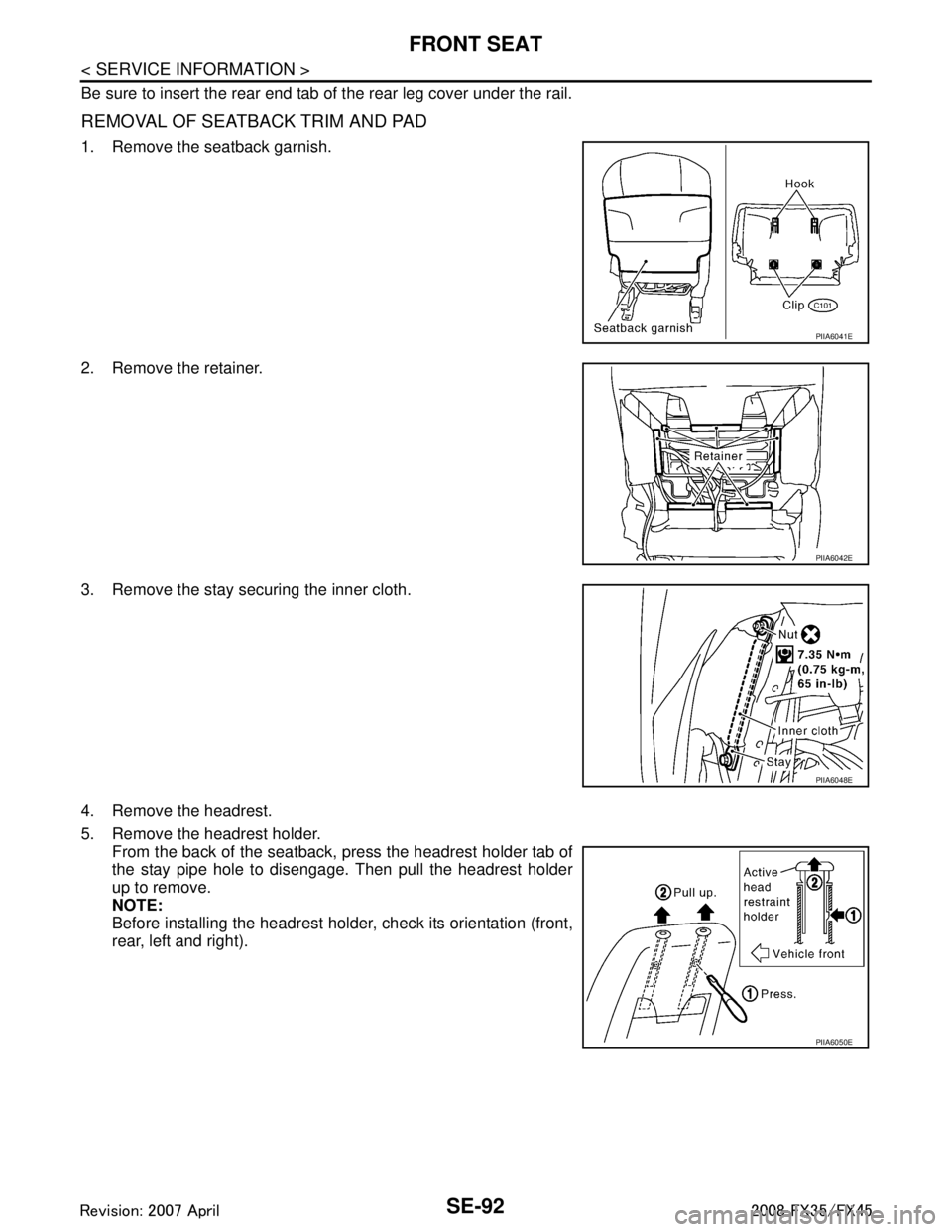
REMOVAL OF SEATBACK TRIM AND PAD
1. Remove the seatback garnish.
2. Remove the retainer.
3. Remove the stay securing the inner cloth.
4. Remove the headrest.
5. Remove the headrest holder.From the back of the seatback, press the headrest holder tab of
the stay pipe hole to disengage. Then pull the headrest holder
up to remove.
NOTE:
Before installing the headrest holder , check its orientation (front,
rear, left and right).
PIIA6041E
PIIA6042E
PIIA6048E
PIIA6050E
3AA93ABC3ACD3AC03ACA3AC03AC63AC53A913A773A893A873A873A8E3A773A983AC73AC93AC03AC3
3A893A873A873A8F3A773A9D3AAF3A8A3A8C3A863A9D3AAF3A8B3A8C
Page 3747 of 3924
SRS-10
< SERVICE INFORMATION >
SUPPLEMENTAL RESTRAINT SYSTEM (SRS)
Front Seat Belt Pre-te nsioner with Load Limiter
INFOID:0000000001524155
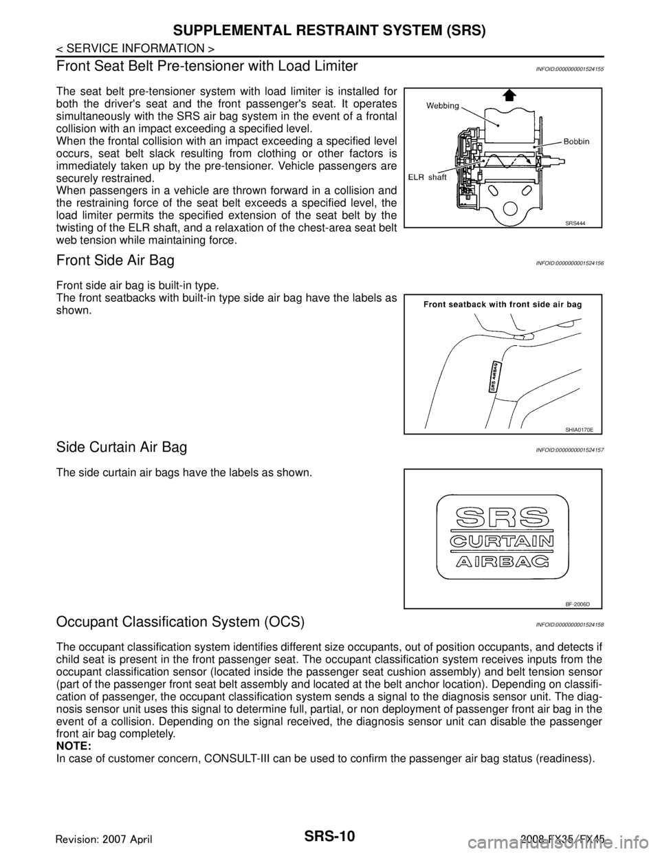
The seat belt pre-tensioner system wi th load limiter is installed for
both the driver's seat and the front passenger's seat. It operates
simultaneously with the SRS air bag system in the event of a frontal
collision with an impact exceeding a specified level.
When the frontal collision with an impact exceeding a specified level
occurs, seat belt slack resulting from clothing or other factors is
immediately taken up by the pre-tensioner. Vehicle passengers are
securely restrained.
When passengers in a vehicle are thrown forward in a collision and
the restraining force of the seat belt exceeds a specified level, the
load limiter permits the specified extension of the seat belt by the
twisting of the ELR shaft, and a relaxation of the chest-area seat belt
web tension while maintaining force.
Front Side Air BagINFOID:0000000001524156
Front side air bag is built-in type.
The front seatbacks with built-in type side air bag have the labels as
shown.
Side Curtain Air BagINFOID:0000000001524157
The side curtain air bags have the labels as shown.
Occupant Classification System (OCS)INFOID:0000000001524158
The occupant classification system identifies different si ze occupants, out of position occupants, and detects if
child seat is present in the front passenger seat. The oc cupant classification system receives inputs from the
occupant classification sensor (located inside the pa ssenger seat cushion assembly) and belt tension sensor
(part of the passenger front seat belt assembly and located at the belt anchor location). Depending on classifi-
cation of passenger, the occupant clas sification system sends a signal to the diagnosis sensor unit. The diag-
nosis sensor unit uses this signal to determine full, pa rtial, or non deployment of passenger front air bag in the
event of a collision. Depending on the signal received, the diagnosis sensor unit can disable the passenger
front air bag completely.
NOTE:
In case of customer concern, CONSULT-III can be used to confirm the passenger air bag status (readiness).
SRS444
SHIA0170E
BF-2006D
3AA93ABC3ACD3AC03ACA3AC03AC63AC53A913A773A893A873A873A8E3A773A983AC73AC93AC03AC3
3A893A873A873A8F3A773A9D3AAF3A8A3A8C3A863A9D3AAF3A8B3A8C
Page 3759 of 3924
SRS-22
< SERVICE INFORMATION >
TROUBLE DIAGNOSIS
Diagnosis results previously stored in the memory are displayed on the CONSULT-III screen. The stored
results are not erased until memory erasing is executed.
“TROUBLE DIAG RECORD”
With TROUBLE DIAG RECORD, diagnosis results previ ously erased by a reset operation can be displayed
on the CONSULT-III screen.
“ECU DISCRIMINATED NO.”
The diagnosis sensor unit for each vehicle model is assigned with its own, individual classification number.
This number will be displayed on the CONSULT-III scr een, as shown. When replacing the diagnosis sensor
unit, refer to the part number for the compatibility. Af ter installation, replacement with a correct unit can be
checked by confirming this classification number on the CONSULT-III screen.
After repair, make sure the discriminated number of diagnosis sensor unit installed to vehicle are same.
Refer to SRS-44, "
Removal and Installation".
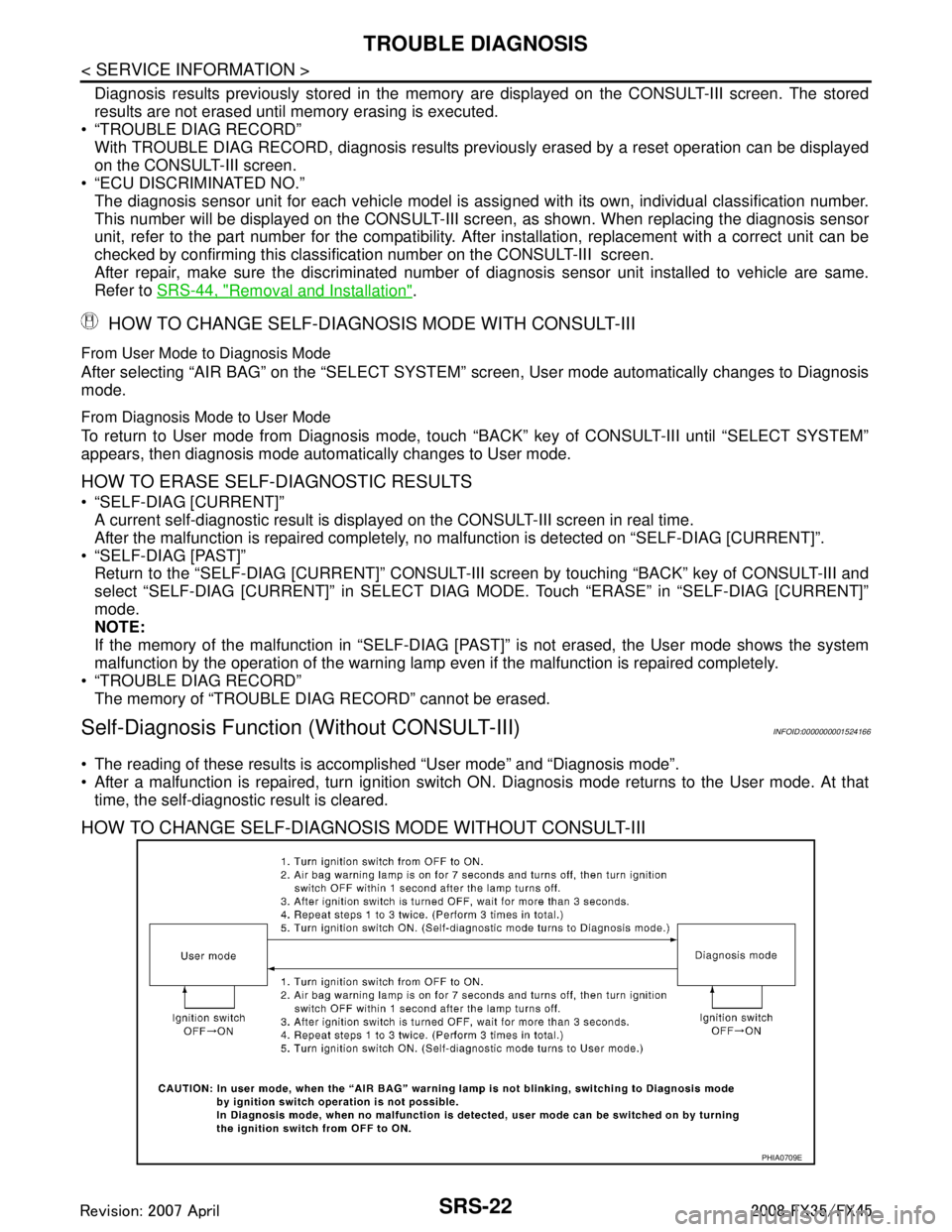
HOW TO CHANGE SELF-DIAGNOSIS MODE WITH CONSULT-III
From User Mode to Diagnosis Mode
After selecting “AIR BAG” on the “SELECT SYSTEM” screen, User mode automatically changes to Diagnosis
mode.
From Diagnosis Mode to User Mode
To return to User mode from Diagnosis mode, touch “BACK” key of CONSULT-III until “SELECT SYSTEM”
appears, then diagnosis mode automat ically changes to User mode.
HOW TO ERASE SELF-DIAGNOSTIC RESULTS
“SELF-DIAG [CURRENT]”
A current self-diagnostic result is displayed on the CONSULT-III screen in real time.
After the malfunction is repaired completely, no malfunction is detected on “SELF-DIAG [CURRENT]”.
“SELF-DIAG [PAST]” Return to the “SELF-DIAG [CURRENT]” CONSULT-III screen by touching “BACK” key of CONSULT-III and
select “SELF-DIAG [CURRENT]” in SELECT DIAG MODE. Touch “ERASE” in “SELF-DIAG [CURRENT]”
mode.
NOTE:
If the memory of the malfunction in “SELF-DIAG [P AST]” is not erased, the User mode shows the system
malfunction by the operation of the warning lamp even if the malfunction is repaired completely.
“TROUBLE DIAG RECORD”
The memory of “TROUBLE DI AG RECORD” cannot be erased.
Self-Diagnosis Function (Without CONSULT-III)INFOID:0000000001524166
The reading of these results is accomplished “User mode” and “Diagnosis mode”.
After a malfunction is repaired, turn ignition switch ON. Diagnosis mode returns to the User mode. At that
time, the self-diagnostic result is cleared.
HOW TO CHANGE SELF-DIAGNOSIS MODE WITHOUT CONSULT-III
PHIA0709E
3AA93ABC3ACD3AC03ACA3AC03AC63AC53A913A773A893A873A873A8E3A773A983AC73AC93AC03AC3
3A893A873A873A8F3A773A9D3AAF3A8A3A8C3A863A9D3AAF3A8B3A8C
Page 3761 of 3924
![INFINITI FX35 2008 Service Manual
SRS-24
< SERVICE INFORMATION >
TROUBLE DIAGNOSIS
Trouble Diagnosis with CONSULT-III
INFOID:0000000001524168
DIAGNOSTIC PROCEDURE
DTC No. Index (“SELF-DIAG [ CURRENT]” “SELF-DIAG [PAST]” or INFINITI FX35 2008 Service Manual
SRS-24
< SERVICE INFORMATION >
TROUBLE DIAGNOSIS
Trouble Diagnosis with CONSULT-III
INFOID:0000000001524168
DIAGNOSTIC PROCEDURE
DTC No. Index (“SELF-DIAG [ CURRENT]” “SELF-DIAG [PAST]” or](/manual-img/42/57017/w960_57017-3760.png)
SRS-24
< SERVICE INFORMATION >
TROUBLE DIAGNOSIS
Trouble Diagnosis with CONSULT-III
INFOID:0000000001524168
DIAGNOSTIC PROCEDURE
DTC No. Index (“SELF-DIAG [ CURRENT]” “SELF-DIAG [PAST]” or TROUBLE DIAG RECORD)
Air bag is deployed.
Seat belt pre-tensioner is deployed. Go to
SRS-47, "For Frontal Colli-
sion" or SRS-48, "For Side Collision"
Diagnosis sensor unit is malfunction-
ing.
Air bag power supply circuit is mal-
functioning.
SRS air bag warning lamp circuit is malfunctioning. Go to
SRS-32, "
Trouble Diagnosis:
"AIR BAG" Warning Lamp Does Not
Turn OFF".
Diagnosis sensor unit is malfunction- ing.
Air bag warning lamp circuit is mal-
functioning. Go to
SRS-32, "
Trouble Diagnosis:
"AIR BAG" Warning Lamp Does Not
Turn ON".
“AIR BAG” warning lamp operation — User mode
—
SRS condition Reference item
SHIA0013E
SHIA0014E
Diagnostic mode Description
SELF-DIAG RESULT The self-d iagnosis result is Displayed. (SELF-DIAG [ CURRENT], [PAST], [RECORD])
ECU DISCRIMINATED No. The parts number of diagnosis sensor units displayed.
Diagnostic item Explanation Repair order
“Recheck SRS at each replacement”
NO DTC IS DETECT-
ED. When malfunction is in-
dicated by the “AIR
BAG” warning lamp in
User mode. Low battery voltage (Less than 9V)
Self-diagnostic result “SELF-DIAG
[PAST]” (previously stored in the
memory) might not be erased after re-
pair.
Intermittent malfunction has been de- tected in the past. Go to
SRS-21, "
CONSULT-III Func-
tion".
No malfunction is detected. —
DIAGNOSIS SENSOR
UNIT (CONTROL UNIT)
[B1001-B1015] Diagnosis sensor is out of order. Replace diagnosis sensor unit.
(ACU)
3AA93ABC3ACD3AC03ACA3AC03AC63AC53A913A773A893A873A873A8E3A773A983AC73AC93AC03AC3
3A893A873A873A8F3A773A9D3AAF3A8A3A8C3A863A9D3AAF3A8B3A8C
Page 3771 of 3924
SRS-34
< SERVICE INFORMATION >
DRIVER AIR BAG MODULE
DRIVER AIR BAG MODULE
Removal and InstallationINFOID:0000000001327764
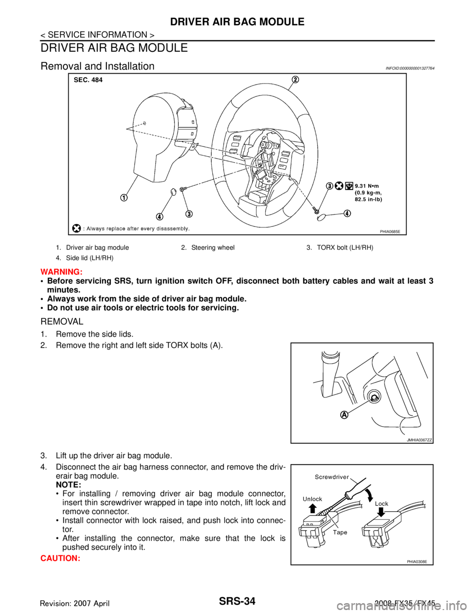
WARNING:
Before servicing SRS, turn ignition switch OFF, disconnect both ba ttery cables and wait at least 3
minutes.
Always work from the side of driver air bag module.
Do not use air tools or el ectric tools for servicing.
REMOVAL
1. Remove the side lids.
2. Remove the right and left side TORX bolts (A).
3. Lift up the driver air bag module.
4. Disconnect the air bag harness connector, and remove the driv-
erair bag module.
NOTE:
For installing / removing driver air bag module connector,insert thin screwdriver wrapped in tape into notch, lift lock and
remove connector.
Install connector with lock raised, and push lock into connec- tor.
After installing the connector, make sure that the lock is pushed securely into it.
CAUTION:
PHIA0685E
1. Driver air bag module 2. Steering wheel 3. TORX bolt (LH/RH)
4. Side lid (LH/RH)
JMHIA0367ZZ
PHIA0308E
3AA93ABC3ACD3AC03ACA3AC03AC63AC53A913A773A893A873A873A8E3A773A983AC73AC93AC03AC3
3A893A873A873A8F3A773A9D3AAF3A8A3A8C3A863A9D3AAF3A8B3A8C
Page 3772 of 3924
DRIVER AIR BAG MODULESRS-35
< SERVICE INFORMATION >
C
DE
F
G
I
J
K L
M A
B
SRS
N
O P
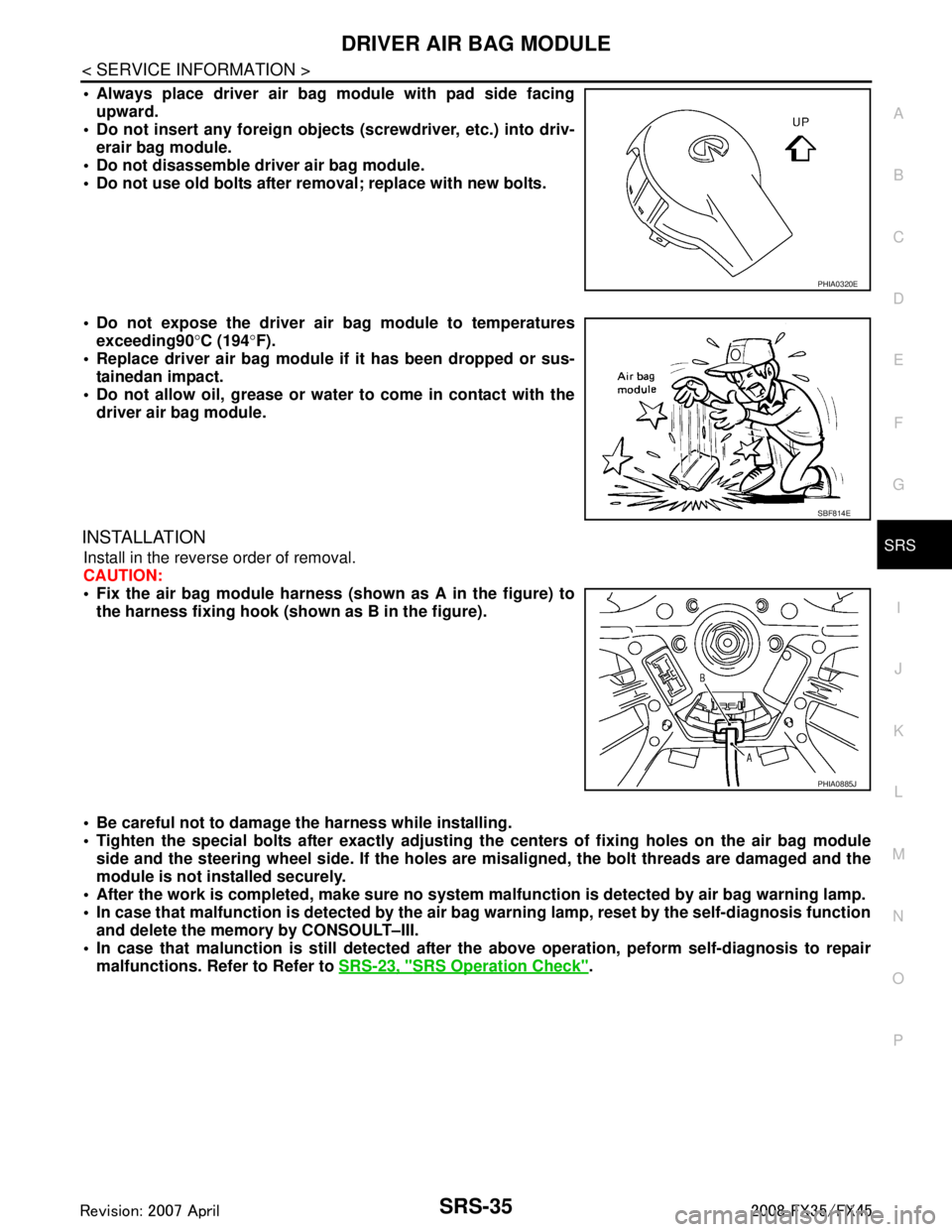
Always place driver air bag module with pad side facing upward.
Do not insert any foreign objects (screwdriver, etc.) into driv-
erair bag module.
Do not disassemble driver air bag module.
Do not use old bolts after removal; replace with new bolts.
Do not expose the driver air bag module to temperatures exceeding90 °C (194 °F).
Replace driver air bag module if it has been dropped or sus-
tainedan impact.
Do not allow oil, grease or water to come in contact with the
driver air bag module.
INSTALLATION
Install in the reverse order of removal.
CAUTION:
Fix the air bag module harness (shown as A in the figure) to
the harness fixing hook (s hown as B in the figure).
Be careful not to damage the harness while installing.
Tighten the special bolts after exactly adjusting the centers of fi xing holes on the air bag module
side and the steering wheel side. If the holes are misaligned, the bolt threads are damaged and the
module is not installed securely.
After the work is completed, make sure no system malfunction is detected by air bag warning lamp.
In case that malfunction is detected by the air ba g warning lamp, reset by the self-diagnosis function
and delete the memory by CONSOULT–III.
In case that malunction is still detected after th e above operation, peform self-diagnosis to repair
malfunctions. Refer to Refer to SRS-23, "
SRS Operation Check".
PHIA0320E
SBF814E
PHIA0885J
3AA93ABC3ACD3AC03ACA3AC03AC63AC53A913A773A893A873A873A8E3A773A983AC73AC93AC03AC3
3A893A873A873A8F3A773A9D3AAF3A8A3A8C3A863A9D3AAF3A8B3A8C
Page 3774 of 3924
SPIRAL CABLESRS-37
< SERVICE INFORMATION >
C
DE
F
G
I
J
K L
M A
B
SRS
N
O P
CAUTION:
The spiral cable may snap by steering operation if the cable is
installed in an improper position.
The neutral position is set as follows. Turn quietly the spiral cable clockwise to the end position.
Then turn it counterclockwise (about 2 and half turns) and
stop turning at the point on which the stopper insertion holes
are in the same position.
The service part is installed in the neutral position by the
stopper and can be set without adjusting after the stopper is
removed.
Do not turn the spiral cable r ashly and also beyond the limit
number of turns. (These will cause cable snap.)
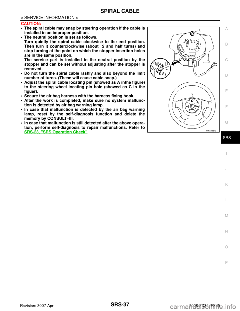
Adjust the spiral cable locating pin (showed as A inthe figure) to the steering wheel locating pin hole (showed as C in the
figuer).
Secure the air bag harness wi th the harness fixing hook.
After the work is completed, make sure no system malfunc- tion is detected by air bag warning lamp.
In case that malfunction is detected by the air bag warning lamp, reset by the self-diagnosis function and delete the
memory by CONSULT −III.
In case that malfunction is still detected after the above opera-
tion, perform self-diagnosis to repair malfunctions. Refer to
SRS-23, "
SRS Operation Check".PHIA0887J
3AA93ABC3ACD3AC03ACA3AC03AC63AC53A913A773A893A873A873A8E3A773A983AC73AC93AC03AC3
3A893A873A873A8F3A773A9D3AAF3A8A3A8C3A863A9D3AAF3A8B3A8C