2008 INFINITI FX35 ECU
[x] Cancel search: ECUPage 3777 of 3924
SRS-40
< SERVICE INFORMATION >
SIDE CURTAIN AIR BAG MODULE
SIDE CURTAIN AIR BAG MODULE
Removal and InstallationINFOID:0000000001327767
WARNING:
Before servicing SRS, turn ignition switch OFF, disconnect both ba ttery cables and wait at least 3
minutes.
Always work from the side of th e side curtain air bag module.
Do not use air tools or el ectric tools for servicing.
REMOVAL
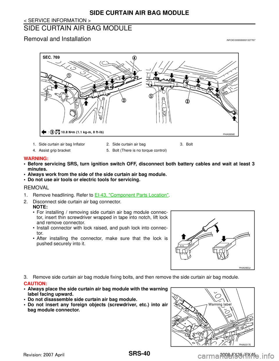
1. Remove headlining. Refer to EI-43, "Component Parts Location".
2. Disconnect side curtain air bag connector. NOTE:
For installing / removing side curtain air bag module connec-
tor, insert thin screwdriver wrapped in tape into notch, lift lock
and remove connector.
Install connector with lock raised, and push lock into connec- tor.
After installing the connector, make sure that the lock is
pushed securely into it.
3. Remove side curtain air bag module fixing bolts, and then remove the side curtain air bag module.
CAUTION:
Always place the side curtain ai r bag module with the warning
label facing upward.
Do not disassemble side cu rtain air bag module.
Do not insert any foreign object s (screwdriver, etc.) into air
bag module connector.
1. Side curtain air bag Inflator 2. Side curtain air bag 3. Bolt
4. Assist grip bracket 5. Bolt (There is no torque control)
PHIA0656E
PHIA0953J
PHIA0317E
3AA93ABC3ACD3AC03ACA3AC03AC63AC53A913A773A893A873A873A8E3A773A983AC73AC93AC03AC3
3A893A873A873A8F3A773A9D3AAF3A8A3A8C3A863A9D3AAF3A8B3A8C
Page 3781 of 3924
SRS-44
< SERVICE INFORMATION >
DIAGNOSIS SENSOR UNIT
DIAGNOSIS SENSOR UNIT
Removal and InstallationINFOID:0000000001327771
WARNING:
Before servicing SRS, turn ignition switch OFF, disconnect both ba ttery cables and wait at least 3
minutes.
Do not use air tools or el ectric tools for servicing.
REMOVAL
1. Disconnect each harness connector for the ai r bag module and seat belt pre-tensioner.
2. Remove center console. Refer to IP-11, "
Removal and Installation".
3. Disconnect diagnosis sensor unit connector.
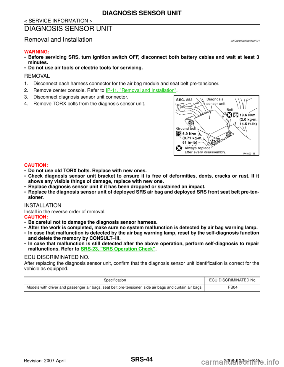
4. Remove TORX bolts from the diagnosis sensor unit.
CAUTION:
Do not use old TORX bolts. Replace with new ones.
Check diagnosis sensor unit bracket to ensure it is free of deformities, dents, cracks or rust. If it
shows any visible things of damage, replace with new one.
Replace diagnosis sensor unit if it has been dropped or sustained an impact.
Replace the diagnosis sensor unit of deployed SRS air bag and deployed SRS front seat belt pre-ten-
sioner.
INSTALLATION
Install in the reverse order of removal.
CAUTION:
Be careful not to damage the diagnosis sensor harness.
After the work is completed, make sure no system malfunction is detected by air bag warning lamp.
In case that malfunction is detected by the air ba g warning lamp, reset by the self-diagnosis function
and delete the memory by CONSULT −III.
In case that malfunction is still de tected after the above operation, perform self-diagnosis to repair
malfunctions. Refer to SRS-23, "
SRS Operation Check".
ECU DISCRIMINATED NO.
After replacing the diagnosis sensor unit, confirm that t he diagnosis sensor unit identification is correct for the
vehicle as equipped.
PHIA0315E
Specification ECU DISCRIMINATED No.
Models with driver and passenger air bags, seat belt pre-tensioner, side air bags and curtain air bags FB04
3AA93ABC3ACD3AC03ACA3AC03AC63AC53A913A773A893A873A873A8E3A773A983AC73AC93AC03AC3
3A893A873A873A8F3A773A9D3AAF3A8A3A8C3A863A9D3AAF3A8B3A8C
Page 3784 of 3924
COLLISION DIAGNOSISSRS-47
< SERVICE INFORMATION >
C
DE
F
G
I
J
K L
M A
B
SRS
N
O P
COLLISION DIAGNOSIS
For Frontal CollisionINFOID:0000000001327773
To repair the SRS, perform the following steps.
When SRS (except the front side air bag and sidecurt ain air bag modules) is activated in a collision:
1. Replace the diagnosis sensor unit.
2. Remove the air bag modules (except the front side air bag modulesand side curtain air bag modules),
crash zone sensor assembly, bracket andseat belt pre-tensioner assemblies.
3. Check the SRS components using the table below:
- Replace any SRS components showing visible signs of damage (dents,cracks and deformation).
4. Install new air bag modules (except the front side air bag modules and side curtain air bag modules) crash
zone sensor assembly, bracket and seat belt pre-tensioner assemblies.
5. Conduct self-diagnosis using CONSULT-III or “AIR BAG”warning lamp. Refer to SRS-23, "
SRS Operation
Check" for details. Ensure entire SRS operates properly.
When SRS is not acti vated in a collision:
1. Check the SRS components using the table below:
- Replace any SRS components showing visible signs of damage (dents, cracks and deformation).
2. Conduct self-diagnosis using CONSULT-III or “AIR BAG” warning lamp. Refer to SRS-23, "
SRS Operation
Check" for details. Ensure entire SRS operates properly.
When only one front air bag modu le is activated in a collision:
1. Replace the following components:
- Diagnosis sensor unit
- Crash zone sensor
- Activated front air bag and seat belt pre-tensioner.
2. Check the other SRS components using the table below. (Refer to “SRS is NOT activated”.)
- Replace any SRS components showing visible signs of damage (dents, cracks and deformation).
3. Conduct self-diagnosis using CONSULT-III or “AIR BAG” warning lamp. Refer to SRS-23, "
SRS Operation
Check" for details. Ensure entire SRS operates properly.
Only one front air bag may inflate a crash, depending on t he crash severity and whether the front occupants
are belted or unbelted. This does not indicate improper performance of the system. Perform self-diagnosis to
make sure the entire SRS operates properly.
SRS INSPECTION (FOR FRONTAL COLLISION)
Part SRS is activated SRS is NOT activated
Driver airbag
module If the Driver airbag has deployed:
REPLACE.
Install with new fasteners. If the Driver air bag has NOT been activated:
[same text as in current manual]
Passenger front
airbag module If the Passenger front airbag has deployed:
REPLACE.
Install with new fasteners. If the Passenger front air bag has NOT been activated:
[same text as in current manual]
Crash zone
sensor If any of the front airbags or seat belt pre-
tensionsers have been activated:
REPLACE the crash zone sensor and bracket
with new fasteners. If the front airbags or seat belt pre-tensionsers have NOT
been activated:
[same text as in current manual]
Seat belt pre-ten-
sioner assemblies If the driver or passenger Seat belt pre-tension-
er has been activated:
REPLACE the seat belt pre-tensioner
assemblies with new fasteners. If the pre-tensioners have NOT been activated:
[same text as in current manual]
Diagnosis sensor
unit If any of the SRS components have been
activated:
REPLACE the Diagnosis sensor unit.
Install with new fasteners. If none of the SRS components have been activated:
[same text as in current manual]
Steering wheel [same text as in current manual]
3AA93ABC3ACD3AC03ACA3AC03AC63AC53A913A773A893A873A873A8E3A773A983AC73AC93AC03AC3
3A893A873A873A8F3A773A9D3AAF3A8A3A8C3A863A9D3AAF3A8B3A8C
Page 3808 of 3924
TF-22
< SERVICE INFORMATION >
TROUBLE DIAGNOSIS
SELF-DIAG RESULT MODE
Drive at 30 km/h or more for approximately 1 minute before performing the self-diagnosis.
Display Item List
CAUTION:
If “CAN COMM CIRCUIT [U1000]” is displayed with other DTCs, first perform the trouble diagnosis for CAN communication
line.
Make sure that ABS warning lamp turns OFF by driving for a minute at vehicle speed of 30 km/h (19 MPH) or more after turn- ing ignition switch “OFF” if AWD warning lamp turns ON with system malfunction of “ABS SYSTEM [C1203]”. AWD warning
lamp may not turn OFF if it is normal unless ignition switch turns OFF at once and engine restarts after that.
How to Erase Self-Diagnostic Results
Before erasing DTC memory, start the engine and drive at 30 km/h or more for approximately 1 minute.
Checkthat ABS warning lamp turns OFF.
NOTE:
Make sure that ABS warning lamp turns OFF by driv ing for a minute at vehicle speed of 30 km/h (19
MPH) or more after turning ignition switch “OFF ” if AWD warning lamp turns ON with system malfunc-
tion of “ABS SYSTE M [C1203]”. AWD warning lamp may not turn OFF if it is normal unless ignition
switch turns OFF at once and engine restarts after that.
DATA MONITOR MODE
Display Item List
Diagnostic test mode Function
ECU part number 4WD control unit part number can be read.
Self-diagnostic results Self-diagnostic results can be read and erased quickly.
Data monitor Input/Output data in the 4WD control unit can be read.
Active test Diagnostic Test Mode in which CONSULT-III drives some actuators apart from the 4WD control unit
and also shifts some parameters in a specified range.
Items (CONSULT-III screen
terms) Diagnostic item is detected when... Check item
CONTROLLER FAILURE
[C1201] Malfunction has occurred inside AWD control unit. TF-24, "
DTC C1201 CON-
TROLLER FAILURE"
ABS SYSTEM
[C1203]Malfunction related to wheel sensor
has been detected by ABS actu-
ator and electric unit (control unit). TF-24, "DTC C1203 ABS
SYSTEM"
4WD SOLENOID
[C1204]
Malfunction related to AWD solenoid has been detected.
TF-25, "DTC C1204 4WD
SOLENOID"
4WD ACTUATOR RLY
[C1205]Malfunction has been detected from AWD actuator relay integrated
with AWD control unit, or malfunction related to AWD solenoid has
been detected. TF-27, "
DTC C1205 4WD
ACTUATOR RLY" or
TF-25,
"DTC C1204 4WD SOLE-
NOID"
ENGINE SIGNAL 1
[C1210] Malfunction has been detected from ECM. TF-28, "DTC C1210 EN-
GINE SIGNAL 1"
CAN COMM CIRCUIT
[U1000]When AWD control unit is not transmitting or receiving CAN commu-
nication signal for 2 seconds or more. TF-28, "DTC U1000 CAN
COMM CIRCUIT"
NO DTC IS DETECTED.
FURTHER TESTING MAY BE
REQUIRED.
No NG item has been detected. —
3AA93ABC3ACD3AC03ACA3AC03AC63AC53A913A773A893A873A873A8E3A773A983AC73AC93AC03AC3
3A893A873A873A8F3A773A9D3AAF3A8A3A8C3A863A9D3AAF3A8B3A8C
Page 3809 of 3924
TROUBLE DIAGNOSISTF-23
< SERVICE INFORMATION >
CEF
G H
I
J
K L
M A
B
TF
N
O P
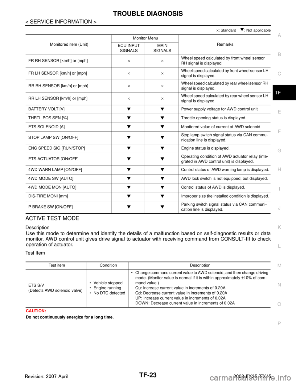
× : Standard : Not applicable
ACTIVE TEST MODE
Description
Use this mode to determine and identify the details of a malfunction based on self-diagnostic results or data
monitor. AWD control unit gives drive signal to actuat or with receiving command from CONSULT-III to check
operation of actuator.
Test Item
CAUTION:
Do not continuously energize for a long time.
Monitored item (Unit) Monitor Menu
Remarks
ECU INPUT
SIGNALS MAIN
SIGNALS
FR RH SENSOR [km/h] or [mph] ××Wheel speed calculated by front wheel sensor
RH signal is displayed.
FR LH SENSOR [km/h] or [mph] ××Wheel speed calculated by front wheel sensor LH
signal is displayed.
RR RH SENSOR [km/h] or [mph] ××Wheel speed calculated by rear wheel sensor RH
signal is displayed.
RR LH SENSOR [km/h] or [mph] ××Wheel speed calculated by rear wheel sensor LH
signal is displayed.
BATTERY VOLT [V] Power supply voltage for AWD control unit
THRTL POS SEN [%] Throttle opening status is displayed.
ETS SOLENOID [A] Monitored value of current at AWD solenoid
STOP LAMP SW [ON/OFF] Stop lamp switch signal status via CAN commu-
nication line is displayed.
ENG SPEED SIG [RUN/STOP] Eng ine status is displayed.
ETS ACTUATOR [ON/OFF] Operating condition of AWD actuator relay (inte-
grated in AWD control unit) is displayed.
4WD WARN LAMP [ON/OFF] Control status of AWD warning lamp is displayed.
4WD MODE SW [AUTO] AWD lock switch is not equipped, but displayed.
4WD MODE MON [AUTO] Control status of AWD is displayed.
DIS-TIRE MONI [mm] Improper size tire installed condition is displayed.
P BRAKE SW [ON/OFF] Parking switch signal status via CAN communi-
cation line is displayed.
Test item Condition Description
ETS S/V
(Detects AWD solenoid valve) Vehicle stopped
Engine running
No DTC detected Change command current value to AWD solenoid, and then change driving
mode. (Monitor value is normal if it is within approximately ±10% of com-
mand value.)
Qu: Increase current value in increments of 0.20A
Qd: Decrease current value in increments of 0.20A
UP: Increase current value in increments of 0.02A
DOWN: Decrease current value in increments of 0.02A
3AA93ABC3ACD3AC03ACA3AC03AC63AC53A913A773A893A873A873A8E3A773A983AC73AC93AC03AC3
3A893A873A873A8F3A773A9D3AAF3A8A3A8C3A863A9D3AAF3A8B3A8C
Page 3826 of 3924
TF-40
< SERVICE INFORMATION >
TRANSFER ASSEMBLY
TRANSFER ASSEMBLY
Removal and InstallationINFOID:0000000001327460
REMOVAL
1. Remove tunnel stay with power tool. Refer to RSU-6, "Removal and Installation".
2. Remove exhaust front tube with power tool. Refer to EX-3
.
3. Remove front and rear propeller shaft. Refer to PR-4
and PR-7.
4. Disconnect transfer assembly harness connector and separate harness from transfer assembly.
5. Remove air breather hose. Refer to TF-39
.
6. Support transfer assembly and transmission assembly with a jack.
7. Remove engine rear member with power tool. Refer to EM-112
(VQ35DE) or EM-237 (VK45DE).
8. Remove transfer mounting bolts and se parate transfer from transmission.
CAUTION:
Secure transfer assembly to a jack.
INSTALLATION
Note the following, and install in the reverse order of removal.
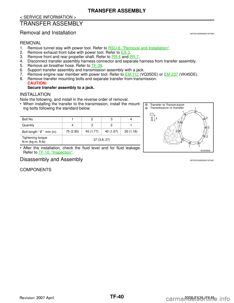
When installing the transfer to the transmission, install the mount-
ing bolts following the standard below.
After the installation, check the fluid level and for fluid leakage. Refer to TF-10, "
Inspection".
Disassembly and AssemblyINFOID:0000000001327461
COMPONENTS
Bolt No. 1234
Quantity 4321
Bolt length “ ” mm (in) 75 (2.95) 45 (1.77) 40 (1.57) 30 (1.18)
Tightening torque
N·m (kg-m, ft-lb) 37 (3.8, 27)
SDIA2284E
3AA93ABC3ACD3AC03ACA3AC03AC63AC53A913A773A893A873A873A8E3A773A983AC73AC93AC03AC3
3A893A873A873A8F3A773A9D3AAF3A8A3A8C3A863A9D3AAF3A8B3A8C
Page 3864 of 3924

WT-24
< SERVICE INFORMATION >
TROUBLE DIAGNOSES
NOTE:
Before performing the self-diagnosis, be sure to register the ID, or else the actual malfunction location may be different from that dis-
played on CONSULT-III.
ACTIVE TEST MODE
Test Item
Flasher
Horn
Warning lamp
ID regist warning
Flat tire warning
How to Perform Trouble Diagnosis for Quick and Accurate RepairINFOID:0000000001327586
INTRODUCTION
Before troubleshooting, verify customer complaints.
If a vehicle malfunction is difficult to reproduce, harnesses, harness connectors or terminals may be mal-
functioning. Hold and shake these parts to make sure they are securely connected.
When using a circuit tester to measure voltage or re sistance of each circuit, be careful not to damage or
deform connector terminals.
WORK FLOW
MONITOR CONDITION SPECIFICATION
VEHICLE SPEED Drive vehicle. V ehicle speed (km/h or MPH)
AIR PRESS FL
AIR PRESS FR
AIR PRESS RR
AIR PRESS RL Drive vehicle for a few minutes.
Tire pressure (kPa or Psi)
or
Ignition switch ON and activation tool is transmitting activation signals.
ID REGST FL 1
ID REGST FR 1
ID REGST RR 1
ID REGST RL 1 Ignition switch ON Registration ID: DONE
No registration ID: YET
WARNING LAMP Low tire pressure
warning lamp on: ON
Low tire pressure wa rning lamp off: OFF
BUZZER Buzzer in combination meter on: ON
Buzzer in combination meter off: OFF
3AA93ABC3ACD3AC03ACA3AC03AC63AC53A913A773A893A873A873A8E3A773A983AC73AC93AC03AC3
3A893A873A873A8F3A773A9D3AAF3A8A3A8C3A863A9D3AAF3A8B3A8C