2008 INFINITI FX35 ECU
[x] Cancel search: ECUPage 2835 of 3924
FUEL SYSTEMFL-3
< SERVICE INFORMATION >
C
DE
F
G H
I
J
K L
M A
FL
NP
O
FUEL SYSTEM
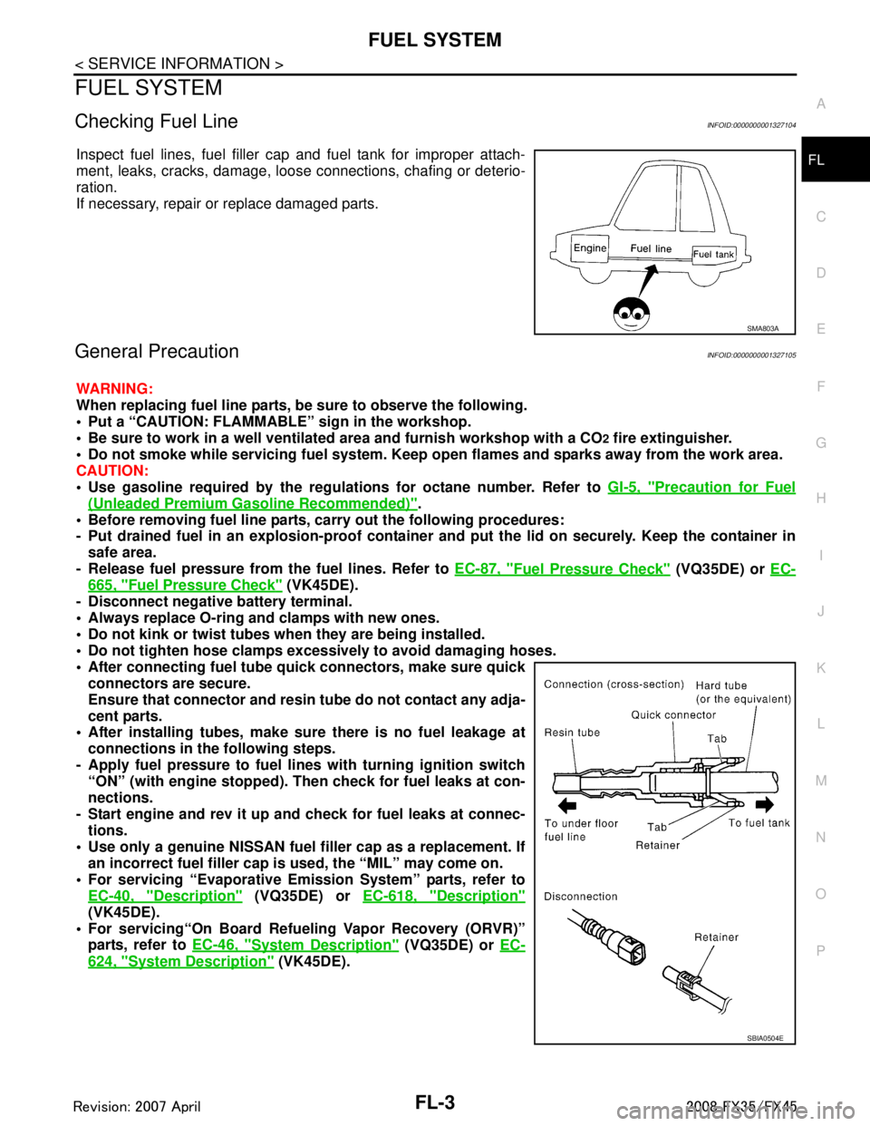
Checking Fuel LineINFOID:0000000001327104
Inspect fuel lines, fuel filler cap and fuel tank for improper attach-
ment, leaks, cracks, damage, loos
e connections, chafing or deterio-
ration.
If necessary, repair or replace damaged parts.
General PrecautionINFOID:0000000001327105
WARNING:
When replacing fuel line parts, be sure to observe the following.
• Put a “CAUTION: FLAMMABLE” sign in the workshop.
Be sure to work in a well ventila ted area and furnish workshop with a CO
2 fire extinguisher.
Do not smoke while servicing fuel system. Keep open flames and sparks away from the work area.
CAUTION:
Use gasoline required by the regulations for octane number. Refer to GI-5, "
Precaution for Fuel
(Unleaded Premium Gasoline Recommended)".
Before removing fuel line parts, carry out the following procedures:
- Put drained fuel in an explosion-proof containe r and put the lid on securely. Keep the container in
safe area.
- Release fuel pressure from th e fuel lines. Refer to EC-87, "
Fuel Pressure Check" (VQ35DE) or EC-
665, "Fuel Pressure Check" (VK45DE).
- Disconnect negative battery terminal.
Always replace O-ring and clamps with new ones.
Do not kink or twist tubes when they are being installed.
Do not tighten hose clamps excessi vely to avoid damaging hoses.
After connecting fuel tube qu ick connectors, make sure quick
connectors are secure.
Ensure that connector and resin tube do not contact any adja-
cent parts.
After installing tubes, make su re there is no fuel leakage at
connections in the following steps.
- Apply fuel pressure to fuel li nes with turning ignition switch
“ON” (with engine stopped). Th en check for fuel leaks at con-
nections.
- Start engine and rev it up and check for fuel leaks at connec- tions.
Use only a genuine NISSAN fuel filler cap as a replacement. If
an incorrect fuel filler cap is used, the “MIL” may come on.
For servicing “Evaporative Emi ssion System” parts, refer to
EC-40, "
Description" (VQ35DE) or EC-618, "Description"
(VK45DE).
For servicing“On Board Refueling Vapor Recovery (ORVR)”
parts, refer to EC-46, "
System Description" (VQ35DE) or EC-
624, "System Description" (VK45DE).
SMA803A
SBIA0504E
3AA93ABC3ACD3AC03ACA3AC03AC63AC53A913A773A893A873A873A8E3A773A983AC73AC93AC03AC3
3A893A873A873A8F3A773A9D3AAF3A8A3A8C3A863A9D3AAF3A8B3A8C
Page 2839 of 3924
FUEL LEVEL SENSOR UNIT, FUEL FILTER AND FUEL PUMP ASSEMBLY
FL-7
< SERVICE INFORMATION >
C
D E
F
G H
I
J
K L
M A
FL
NP
O
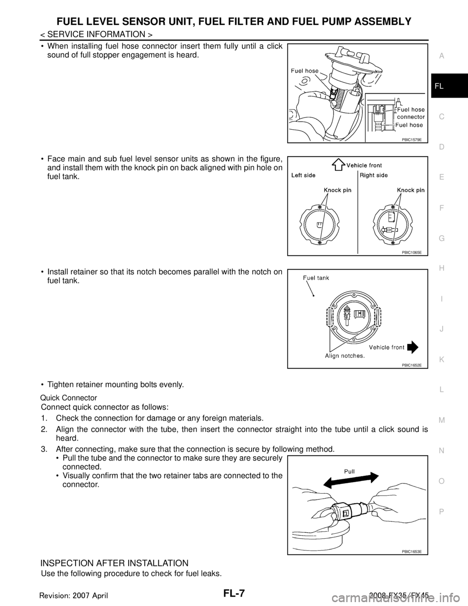
When installing fuel hose connector insert them fully until a click
sound of full stopper engagement is heard.
Face main and sub fuel level sensor units as shown in the figure, and install them with the knock pin on back aligned with pin hole on
fuel tank.
Install retainer so that its notch becomes parallel with the notch on fuel tank.
Tighten retainer mounting bolts evenly.
Quick Connector
Connect quick connector as follows:
1. Check the connection for damage or any foreign materials.
2. Align the connector with the tube, then insert the connector straight into the tube until a click sound is
heard.
3. After connecting, make sure that the connection is secure by following method. Pull the tube and the connector to make sure they are securelyconnected.
Visually confirm that the two retainer tabs are connected to the
connector.
INSPECTION AFTER INSTALLATION
Use the following procedure to check for fuel leaks.
PBIC1579E
PBIC1065E
PBIC1652E
PBIC1653E
3AA93ABC3ACD3AC03ACA3AC03AC63AC53A913A773A893A873A873A8E3A773A983AC73AC93AC03AC3
3A893A873A873A8F3A773A9D3AAF3A8A3A8C3A863A9D3AAF3A8B3A8C
Page 2841 of 3924
FUEL LEVEL SENSOR UNIT, FUEL FILTER AND FUEL PUMP ASSEMBLY
FL-9
< SERVICE INFORMATION >
C
D E
F
G H
I
J
K L
M A
FL
NP
O
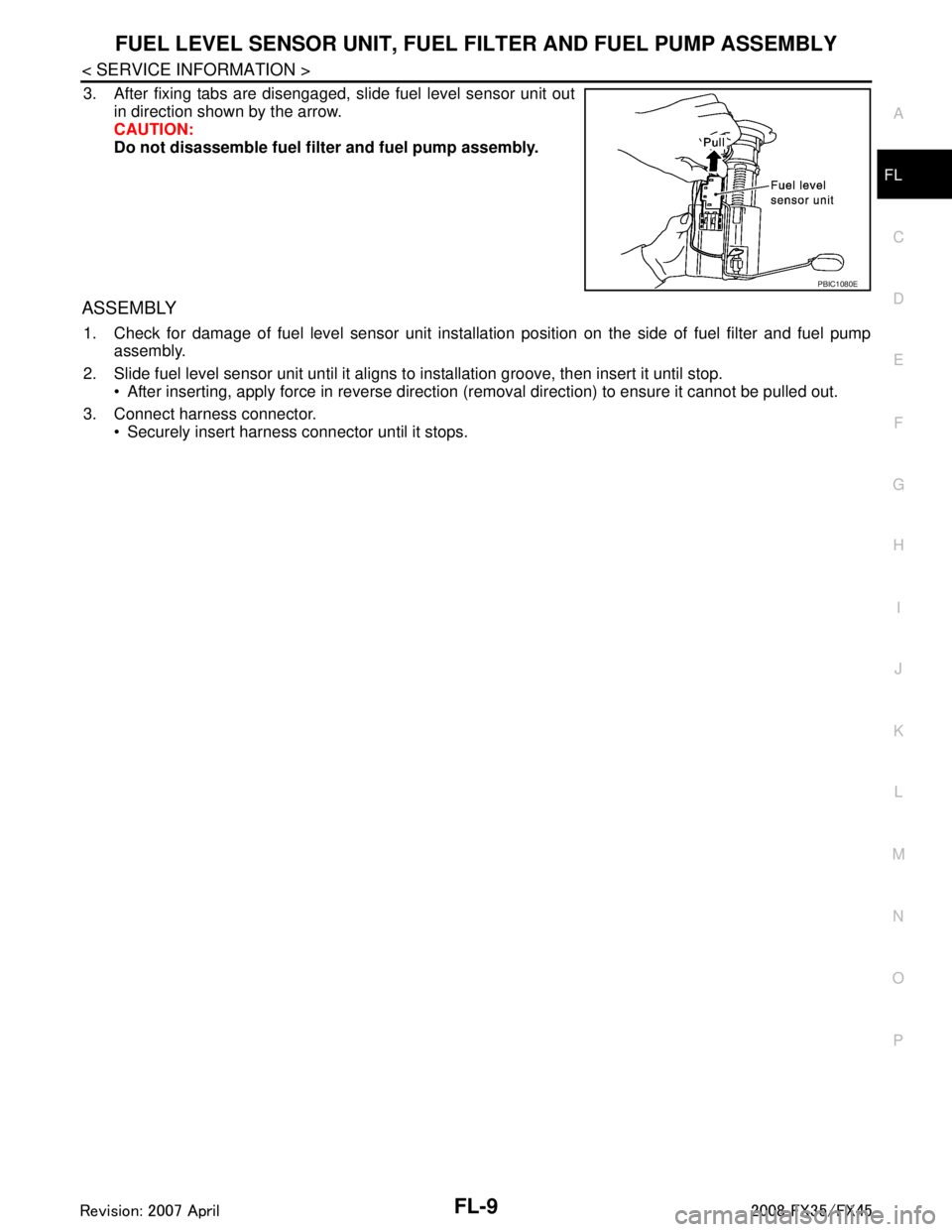
3. After fixing tabs are disengaged, slide fuel level sensor unit out
in direction shown by the arrow.
CAUTION:
Do not disassemble fuel filt er and fuel pump assembly.
ASSEMBLY
1. Check for damage of fuel level sensor unit installa tion position on the side of fuel filter and fuel pump
assembly.
2. Slide fuel level sensor unit until it aligns to installation groove, then insert it until stop. After inserting, apply force in reverse direction (removal direction) to ensure it cannot be pulled out.
3. Connect harness connector. Securely insert harness connector until it stops.
PBIC1080E
3AA93ABC3ACD3AC03ACA3AC03AC63AC53A913A773A893A873A873A8E3A773A983AC73AC93AC03AC3
3A893A873A873A8F3A773A9D3AAF3A8A3A8C3A863A9D3AAF3A8B3A8C
Page 2855 of 3924
COIL SPRING AND STRUTFSU-11
< SERVICE INFORMATION >
C
DF
G H
I
J
K L
M A
B
FSU
N
O P
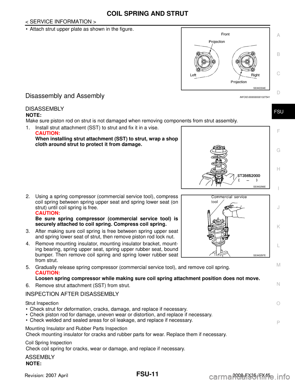
Attach strut upper plate as shown in the figure.
Disassembly and AssemblyINFOID:0000000001327541
DISASSEMBLY
NOTE:
Make sure piston rod on strut is not damaged when removing components from strut assembly.
1. Install strut attachment (SST) to strut and fix it in a vise. CAUTION:
When installing strut attachment (SST) to strut, wrap a shop
cloth around strut to protect it from damage.
2. Using a spring compressor (commercial service tool), compress coil spring between spring upper seat and spring lower seat (on
strut) until coil spring is free.
CAUTION:
Be sure spring compressor (commercial service tool) is
securely attached to coil sp ring. Compress coil spring.
3. After making sure coil spring is free between spring upper seat and spring lower seat of strut, then remove piston rod lock nut.
4. Remove mounting insulator, mounting insulator bracket, mount- ing bearing, spring upper seat, spring upper rubber seat, bound
bumper. Then remove coil spring and spring lower rubber seat
from strut.
5. Gradually release spring compressor (commercial service tool), and remove coil spring. CAUTION:
Loosen spring compressor whil e making sure coil spring attachment position does not move.
6. Remove strut attachment (SST) from strut.
INSPECTION AFTER DISASSEMBLY
Strut Inspection
Check strut for deformation, cracks, damage, and replace if necessary.
Check piston rod for damage, uneven wear or distortion, and replace if necessary.
Check welded and sealed areas for oil leakage, and replace if necessary.
Mounting Insulator and Rubber Parts Inspection
Check mounting insulator for cracks and rubber parts for wear. Replace them if necessary.
Coil Spring Inspection
Check coil spring for cracks, wear or damage, and replace if necessary.
ASSEMBLY
NOTE:
SEIA0334E
SEIA0296E
SEIA0297E
3AA93ABC3ACD3AC03ACA3AC03AC63AC53A913A773A893A873A873A8E3A773A983AC73AC93AC03AC3
3A893A873A873A8F3A773A9D3AAF3A8A3A8C3A863A9D3AAF3A8B3A8C
Page 2856 of 3924
FSU-12
< SERVICE INFORMATION >
COIL SPRING AND STRUT
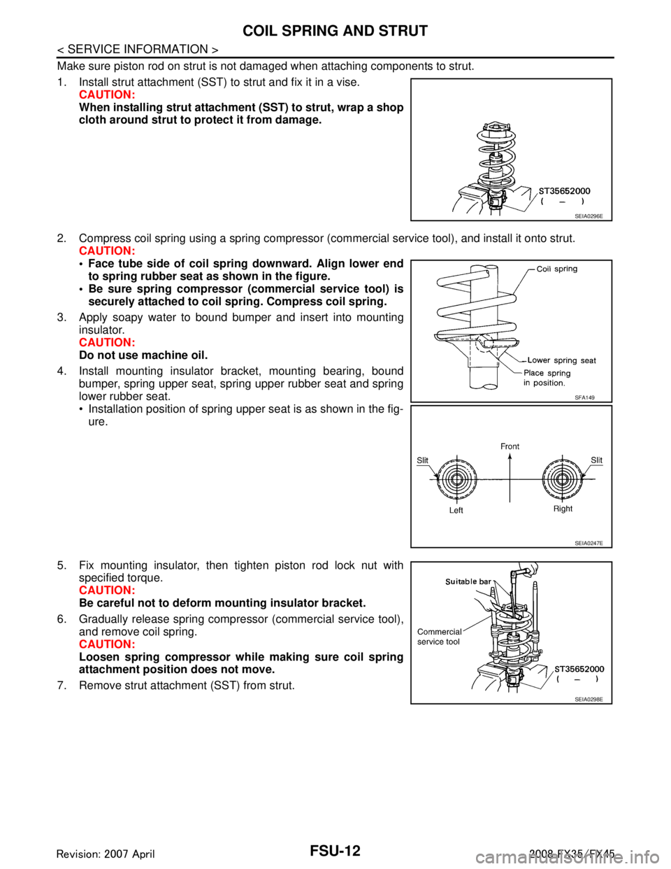
Make sure piston rod on strut is not damaged when attaching components to strut.
1. Install strut attachment (SST) to strut and fix it in a vise.CAUTION:
When installing strut attachment (SST) to strut, wrap a shop
cloth around strut to protect it from damage.
2. Compress coil spring using a spring compressor (c ommercial service tool), and install it onto strut.
CAUTION:
Face tube side of coil spri ng downward. Align lower end
to spring rubber seat as shown in the figure.
Be sure spring compressor (commercial service tool) is securely attached to coil sp ring. Compress coil spring.
3. Apply soapy water to bound bumper and insert into mounting insulator.
CAUTION:
Do not use machine oil.
4. Install mounting insulator bracket, mounting bearing, bound bumper, spring upper seat, spring upper rubber seat and spring
lower rubber seat.
Installation position of spring upper seat is as shown in the fig-ure.
5. Fix mounting insulator, then tighten piston rod lock nut with specified torque.
CAUTION:
Be careful not to deform mounting insulator bracket.
6. Gradually release spring compressor (commercial service tool), and remove coil spring.
CAUTION:
Loosen spring compressor whil e making sure coil spring
attachment position does not move.
7. Remove strut attachment (SST) from strut.
SEIA0296E
SFA149
SEIA0247E
SEIA0298E
3AA93ABC3ACD3AC03ACA3AC03AC63AC53A913A773A893A873A873A8E3A773A983AC73AC93AC03AC3
3A893A873A873A8F3A773A9D3AAF3A8A3A8C3A863A9D3AAF3A8B3A8C
Page 2868 of 3924
GI-6
< SERVICE INFORMATION >
PRECAUTIONS
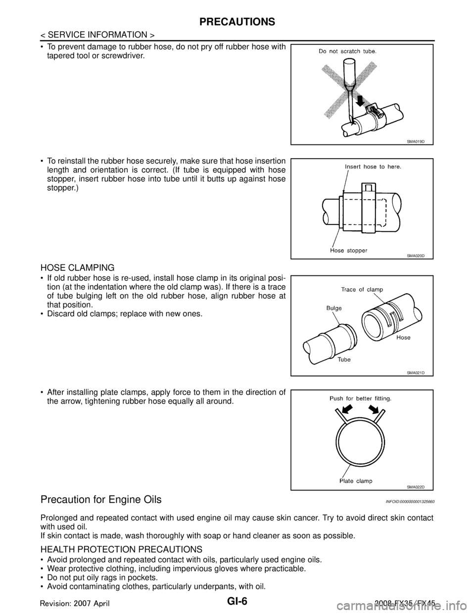
To prevent damage to rubber hose, do not pry off rubber hose withtapered tool or screwdriver.
To reinstall the rubber hose securely, make sure that hose insertion length and orientation is correct. (If tube is equipped with hose
stopper, insert rubber hose into tube until it butts up against hose
stopper.)
HOSE CLAMPING
If old rubber hose is re-used, install hose clamp in its original posi-tion (at the indentation where the old clamp was). If there is a trace
of tube bulging left on the old rubber hose, align rubber hose at
that position.
Discard old clamps; replace with new ones.
After installing plate clamps, apply force to them in the direction of the arrow, tightening rubber hose equally all around.
Precaution for Engine OilsINFOID:0000000001325660
Prolonged and repeated contact with used engine oil may cause skin cancer. Try to avoid direct skin contact
with used oil.
If skin contact is made, wash thoroughly with soap or hand cleaner as soon as possible.
HEALTH PROTECTION PRECAUTIONS
Avoid prolonged and repeated contact with oils, particularly used engine oils.
Wear protective clothing, including impervious gloves where practicable.
Do not put oily rags in pockets.
Avoid contaminating clothes, pa rticularly underpants, with oil.
SMA019D
SMA020D
SMA021D
SMA022D
3AA93ABC3ACD3AC03ACA3AC03AC63AC53A913A773A893A873A873A8E3A773A983AC73AC93AC03AC3
3A893A873A873A8F3A773A9D3AAF3A8A3A8C3A863A9D3AAF3A8B3A8C
Page 2892 of 3924
GI-30
< SERVICE INFORMATION >
SERVICE INFORMATION FOR ELECTRICAL INCIDENT
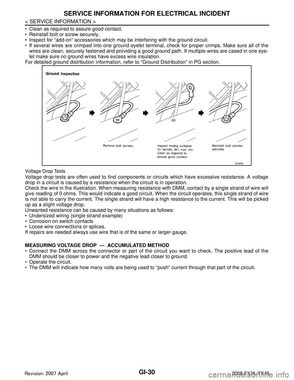
Clean as required to assure good contact.
Reinstall bolt or screw securely.
Inspect for “add-on” accessories which may be interfering with the ground circuit.
If several wires are crimped into one ground eyelet terminal, check for proper crimps. Make sure all of thewires are clean, securely fastened and providing a good ground path. If multiple wires are cased in one eye-
let make sure no ground wires have excess wire insulation.
For detailed ground distribution information, re fer to “Ground Distribution” in PG section.
Voltage Drop Tests
Voltage drop tests are often used to find components or circuits which have excessive resistance. A voltage
drop in a circuit is caused by a resistance when the circuit is in operation.
Check the wire in the illustration. When measuring resist ance with DMM, contact by a single strand of wire will
give reading of 0 ohms. This would indicate a good circui t. When the circuit operates, this single strand of wire
is not able to carry the current. The single strand will have a high resistance to the current. This will be picked
up as a slight voltage drop.
Unwanted resistance can be caused by many situations as follows:
Undersized wiring (single strand example)
Corrosion on switch contacts
Loose wire connections or splices.
If repairs are needed always use wire that is of the same or larger gauge.
MEASURING VOLTAGE DROP — ACCUMULATED METHOD
Connect the DMM across the connector or part of the ci rcuit you want to check. The positive lead of the
DMM should be closer to power and the negative lead closer to ground.
Operate the circuit.
The DMM will indicate how many volts are being used to “push” current through that part of the circuit.
SGI853
3AA93ABC3ACD3AC03ACA3AC03AC63AC53A913A773A893A873A873A8E3A773A983AC73AC93AC03AC3
3A893A873A873A8F3A773A9D3AAF3A8A3A8C3A863A9D3AAF3A8B3A8C
Page 2896 of 3924
GI-34
< SERVICE INFORMATION >
CONSULT-III/GST CHECKING SYSTEM
CONSULT-III/GST CHECKING SYSTEM
DescriptionINFOID:0000000001572193
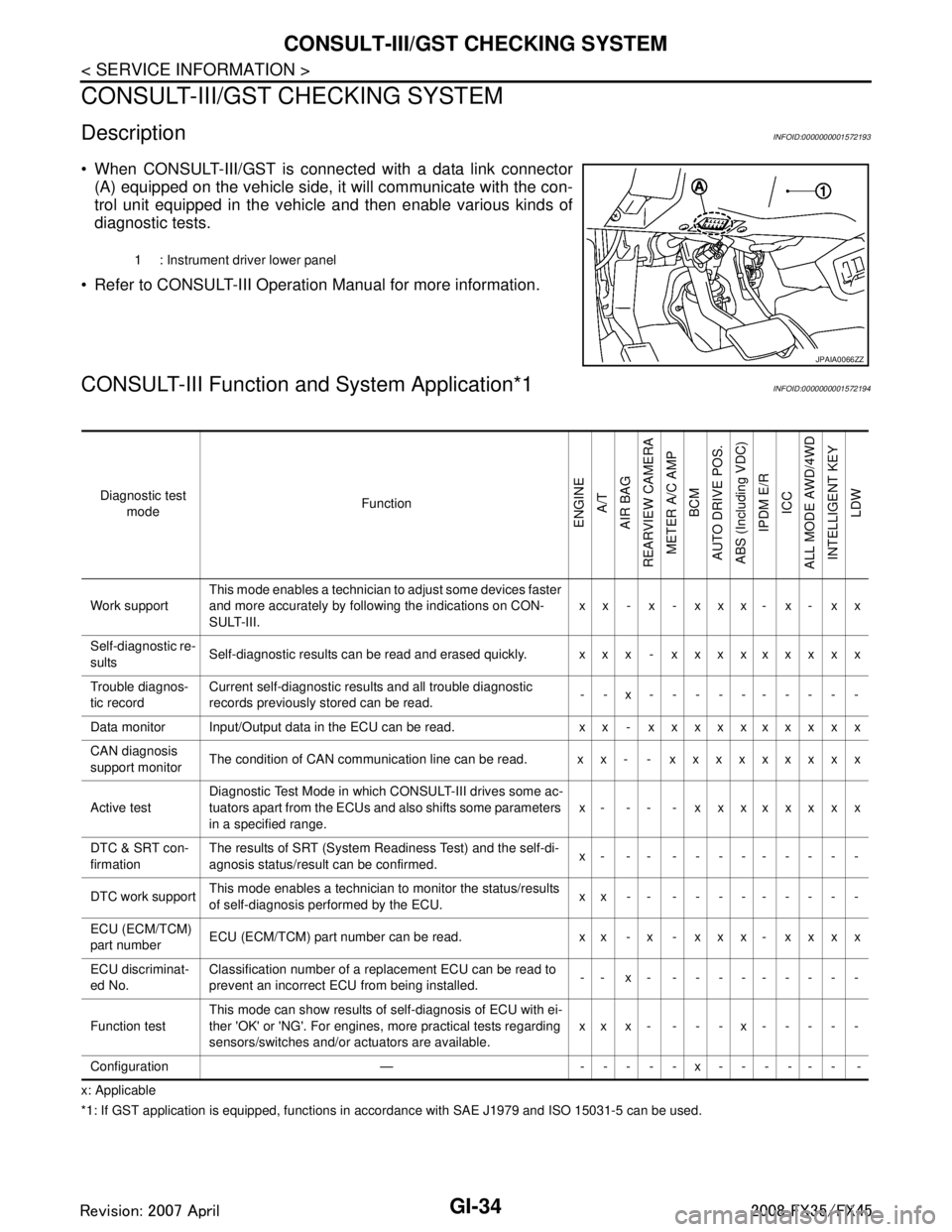
When CONSULT-III/GST is connected with a data link connector
(A) equipped on the vehicle side, it will communicate with the con-
trol unit equipped in the vehicle and then enable various kinds of
diagnostic tests.
Refer to CONSULT-III Operation Manual for more information.
CONSULT-III Function a nd System Application*1INFOID:0000000001572194
x: Applicable
*1: If GST application is eq uipped, functions in accordance with SAE J1979 and ISO 15031-5 can be used.
1 : Instrument driver lower panel
JPAIA0066ZZ
Diagnostic test
mode Function
ENGINE
A/T
AIR BAG
REARVIEW CAMERA
METER A/C AMP BCM
AUTO DRIVE POS.
ABS (Including VDC) IPDM E/R
ICC
ALL MODE AWD/4WD INTELLIGENT KEY LDW
Work support This mode enables a technician to adjust some devices faster
and more accurately by following the indications on CON-
SULT-III. xx - x - xxx- x- xx
Self-diagnostic re-
sults Self-diagnostic results can be read and erased quickly. xxx - xxxxxxxxx
Trouble diagnos-
tic record Current self-diagnostic results and all trouble diagnostic
records previously stored can be read.
--x----------
Data monitor Input/Output data in the ECU can be read. xx - xxxxxxxxxx
CAN diagnosis
support monitor The condition of CAN communication line can be read. xx- - xxxxxxxxx
Active test Diagnostic Test Mode in whic
h CONSULT-III drives some ac-
tuators apart from the ECUs and also shifts some parameters
in a specified range. x- -- - xxxxxxxx
DTC & SRT con-
firmation The results of SRT (System Readiness Test) and the self-di-
agnosis status/result can be confirmed.
x- -- ---------
DTC work support This mode enables a technician to monitor the status/results
of self-diagnosis performed by the ECU. xx-- ---------
ECU (ECM/TCM)
part number ECU (ECM/TCM) part number can be read. x x - x - x x x - x x x x
ECU discriminat-
ed No. Classification number of a replacement ECU can be read to
prevent an incorrect ECU from being installed.
-- x- ---------
Function test This mode can show results of self-diagnosis of ECU with ei-
ther 'OK' or 'NG'. For engines, more practical tests regarding
sensors/switches and/or actuators are available.
xxx- ---x-----
Configuration — -----x------ -
3AA93ABC3ACD3AC03ACA3AC03AC63AC53A913A773A893A873A873A8E3A773A983AC73AC93AC03AC3
3A893A873A873A8F3A773A9D3AAF3A8A3A8C3A863A9D3AAF3A8B3A8C