2008 INFINITI FX35 key
[x] Cancel search: keyPage 3263 of 3924

INTERIOR ROOM LAMPLT-161
< SERVICE INFORMATION >
C
DE
F
G H
I
J
L
M A
B
LT
N
O P
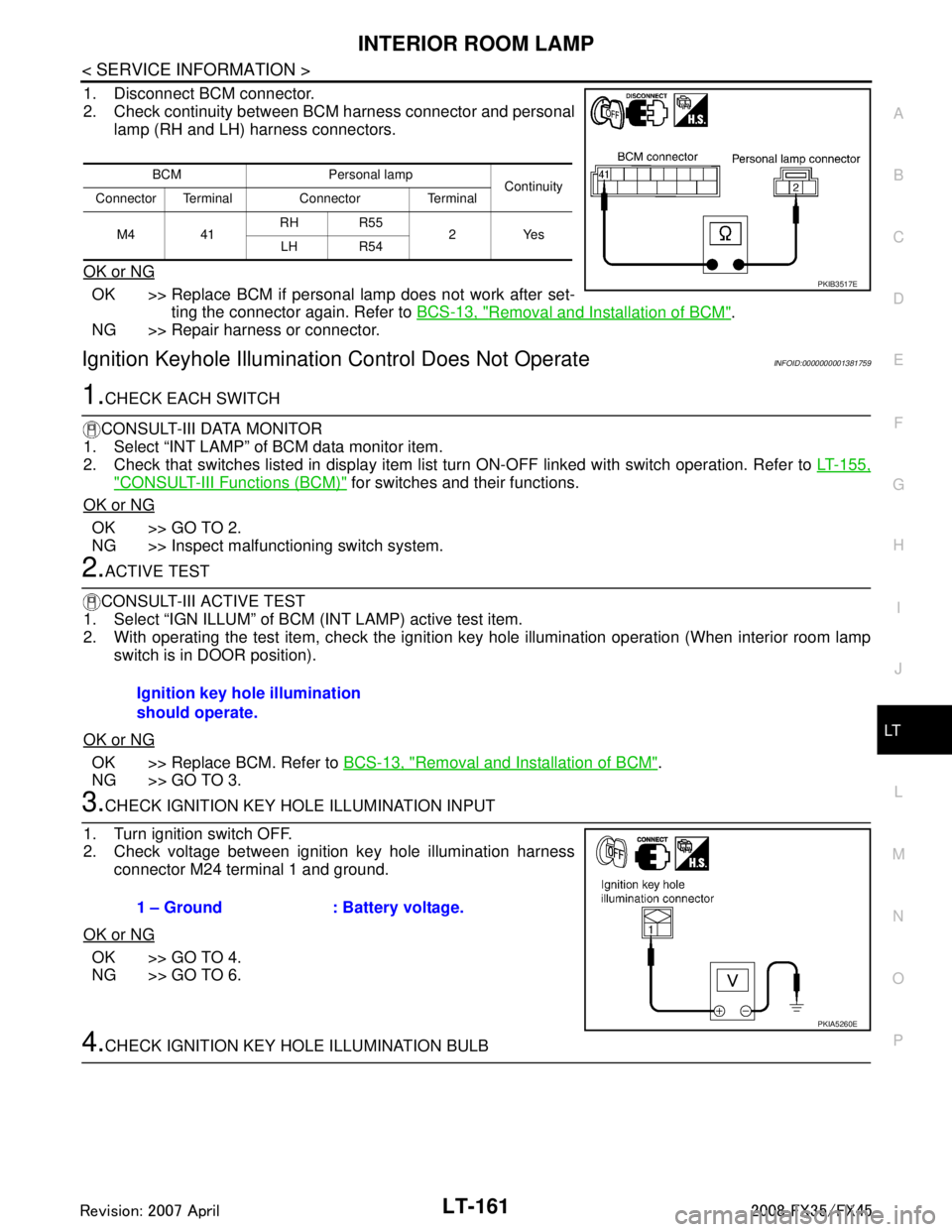
1. Disconnect BCM connector.
2. Check continuity between BCM harness connector and personal lamp (RH and LH) harness connectors.
OK or NG
OK >> Replace BCM if personal lamp does not work after set- ting the connector again. Refer to BCS-13, "
Removal and Installation of BCM".
NG >> Repair harness or connector.
Ignition Keyhole Illumination Control Does Not OperateINFOID:0000000001381759
1.CHECK EACH SWITCH
CONSULT-III DATA MONITOR
1. Select “INT LAMP” of BCM data monitor item.
2. Check that switches listed in display item list turn ON-OFF linked with switch operation. Refer to LT-155,
"CONSULT-III Functions (BCM)" for switches and their functions.
OK or NG
OK >> GO TO 2.
NG >> Inspect malfunctioning switch system.
2.ACTIVE TEST
CONSULT-III ACTIVE TEST
1. Select “IGN ILLUM” of BCM (INT LAMP) active test item.
2. With operating the test item, check the ignition ke y hole illumination operation (When interior room lamp
switch is in DOOR position).
OK or NG
OK >> Replace BCM. Refer to BCS-13, "Removal and Installation of BCM".
NG >> GO TO 3.
3.CHECK IGNITION KEY HOLE ILLUMINATION INPUT
1. Turn ignition switch OFF.
2. Check voltage between ignition key hole illumination harness connector M24 terminal 1 and ground.
OK or NG
OK >> GO TO 4.
NG >> GO TO 6.
4.CHECK IGNITION KEY HOLE ILLUMINATION BULB
BCM Personal lamp Continuity
Connector Terminal Connector Terminal
M4 41 RH R55
2Yes
LH R54
PKIB3517E
Ignition key hole illumination
should operate.
1 – Ground : Battery voltage.
PKIA5260E
3AA93ABC3ACD3AC03ACA3AC03AC63AC53A913A773A893A873A873A8E3A773A983AC73AC93AC03AC3
3A893A873A873A8F3A773A9D3AAF3A8A3A8C3A863A9D3AAF3A8B3A8C
Page 3264 of 3924

LT-162
< SERVICE INFORMATION >
INTERIOR ROOM LAMP
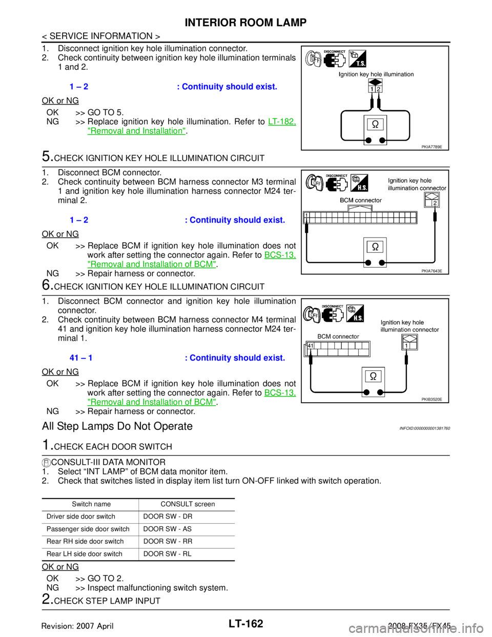
1. Disconnect ignition key hole illumination connector.
2. Check continuity between ignition key hole illumination terminals1 and 2.
OK or NG
OK >> GO TO 5.
NG >> Replace ignition key hole illumination. Refer to LT-182,
"Removal and Installation".
5.CHECK IGNITION KEY HOLE ILLUMINATION CIRCUIT
1. Disconnect BCM connector.
2. Check continuity between BCM harness connector M3 terminal 1 and ignition key hole illumination harness connector M24 ter-
minal 2.
OK or NG
OK >> Replace BCM if ignition key hole illumination does not work after setting the connector again. Refer to BCS-13,
"Removal and Installation of BCM".
NG >> Repair harness or connector.
6.CHECK IGNITION KEY HOLE ILLUMINATION CIRCUIT
1. Disconnect BCM connector and ignition key hole illumination connector.
2. Check continuity between BCM harness connector M4 terminal
41 and ignition key hole illumination harness connector M24 ter-
minal 1.
OK or NG
OK >> Replace BCM if ignition key hole illumination does not work after setting the connector again. Refer to BCS-13,
"Removal and Installation of BCM".
NG >> Repair harness or connector.
All Step Lamps Do Not OperateINFOID:0000000001381760
1.CHECK EACH DOOR SWITCH
CONSULT-III DATA MONITOR
1. Select “INT LAMP” of BCM data monitor item.
2. Check that switches listed in display item list turn ON-OFF linked with switch operation.
OK or NG
OK >> GO TO 2.
NG >> Inspect malfunctioning switch system.
2.CHECK STEP LAMP INPUT 1 – 2 : Continuity should exist.
PKIA7789E
1 – 2 : Continuity should exist.
PKIA7643E
41 – 1 : Continuity should exist.
PKIB3520E
Switch name CONSULT screen
Driver side door switch DOOR SW - DR
Passenger side door switch DOOR SW - AS
Rear RH side door switch DOOR SW - RR
Rear LH side door switch DOOR SW - RL
3AA93ABC3ACD3AC03ACA3AC03AC63AC53A913A773A893A873A873A8E3A773A983AC73AC93AC03AC3
3A893A873A873A8F3A773A9D3AAF3A8A3A8C3A863A9D3AAF3A8B3A8C
Page 3266 of 3924

LT-164
< SERVICE INFORMATION >
INTERIOR ROOM LAMP
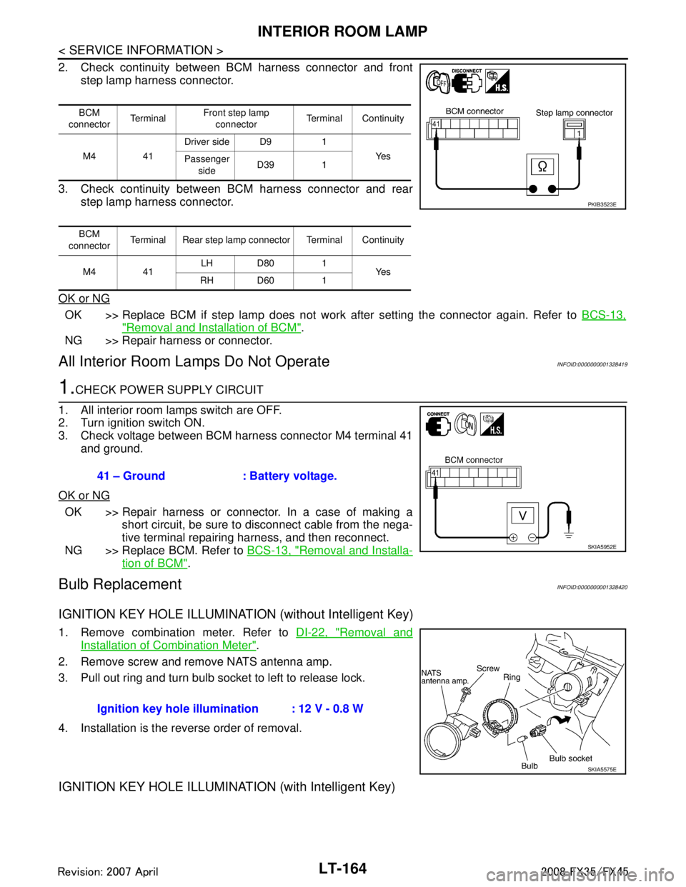
2. Check continuity between BCM harness connector and frontstep lamp harness connector.
3. Check continuity between BCM harness connector and rear step lamp harness connector.
OK or NG
OK >> Replace BCM if step lamp does not work after setting the connector again. Refer to BCS-13,
"Removal and Installation of BCM".
NG >> Repair harness or connector.
All Interior Room La mps Do Not OperateINFOID:0000000001328419
1.CHECK POWER SUPPLY CIRCUIT
1. All interior room lamps switch are OFF.
2. Turn ignition switch ON.
3. Check voltage between BCM harness connector M4 terminal 41 and ground.
OK or NG
OK >> Repair harness or connector. In a case of making a short circuit, be sure to disconnect cable from the nega-
tive terminal repairing harness, and then reconnect.
NG >> Replace BCM. Refer to BCS-13, "
Removal and Installa-
tion of BCM".
Bulb ReplacementINFOID:0000000001328420
IGNITION KEY HOLE ILLUMINATION (without Intelligent Key)
1. Remove combination meter. Refer to DI-22, "Removal and
Installation of Combination Meter".
2. Remove screw and remove NATS antenna amp.
3. Pull out ring and turn bulb socket to left to release lock.
4. Installation is the reverse order of removal.
IGNITION KEY HOLE ILLUMINA TION (with Intelligent Key)
BCM
connector Te r m i n a l Front step lamp
connector Terminal Continuity
M4 41 Driver side D9 1
Ye s
Passenger
side D39 1
BCM
connector Terminal Rear step lamp connector Terminal Continuity
M4 41 LH D80 1
Ye s
RH D60 1
PKIB3523E
41 – Ground : Battery voltage.
SKIA5952E
Ignition key hole illu mination : 12 V - 0.8 W
SKIA5575E
3AA93ABC3ACD3AC03ACA3AC03AC63AC53A913A773A893A873A873A8E3A773A983AC73AC93AC03AC3
3A893A873A873A8F3A773A9D3AAF3A8A3A8C3A863A9D3AAF3A8B3A8C
Page 3267 of 3924

INTERIOR ROOM LAMPLT-165
< SERVICE INFORMATION >
C
DE
F
G H
I
J
L
M A
B
LT
N
O P
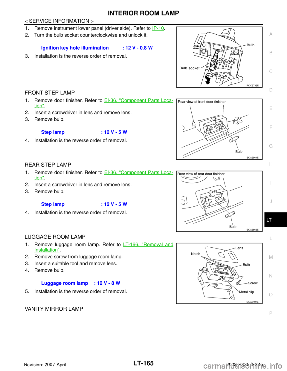
1. Remove instrument lower panel (driver side). Refer to IP-10.
2. Turn the bulb socket counterclockwise and unlock it.
3. Installation is the reverse order of removal.
FRONT STEP LAMP
1. Remove door finisher. Refer to EI-36, "Component Parts Loca-
tion".
2. Insert a screwdriver in lens and remove lens.
3. Remove bulb.
4. Installation is the reverse order of removal.
REAR STEP LAMP
1. Remove door finisher. Refer to EI-36, "Component Parts Loca-
tion".
2. Insert a screwdriver in lens and remove lens.
3. Remove bulb.
4. Installation is the reverse order of removal.
LUGGAGE ROOM LAMP
1. Remove luggage room lamp. Refer to LT-166, "Removal and
Installation".
2. Remove screw from luggage room lamp.
3. Insert a suitable tool and remove lens.
4. Remove bulb.
5. Installation is the reverse order of removal.
VANITY MIRROR LAMP
Ignition key hole illumination : 12 V - 0.8 W
PKIC9733E
Step lamp : 12 V - 5 W
SKIA5564E
Step lamp : 12 V - 5 W
SKIA5565E
Luggage room lamp : 12 V - 8 W
SKIA6197E
3AA93ABC3ACD3AC03ACA3AC03AC63AC53A913A773A893A873A873A8E3A773A983AC73AC93AC03AC3
3A893A873A873A8F3A773A9D3AAF3A8A3A8C3A863A9D3AAF3A8B3A8C
Page 3285 of 3924

BULB SPECIFICATIONSLT-183
< SERVICE INFORMATION >
C
DE
F
G H
I
J
L
M A
B
LT
N
O P
BULB SPECIFICATIONS
HeadlampINFOID:0000000001328429
Exterior LampINFOID:0000000001328430
Interior Lamp/IlluminationINFOID:0000000001328431
Item Wattage (W)
High/Low (Xenon type) 35 (D2S)
Item Wattage (W)
Front combination lamp Front turn signal lamp 21 (amber)
Daytime/Parking lamp 21/5
Front side marker lamp 3.8
Rear combination lamp Stop/Tail lamp and Rear Turn signal lamp LED
Rear side marker lamp 3.8
Front fog lamp 35 (H8)
Back-up lamp 18
License plate lamp 5
High-mounted stop lamp (back door mount) LED
Item Wattage (W)
Map lamp 8
Interior room lamp 10
Personal lamp 8
Luggage room lamp 8
Step lamp 5
Glove box lamp 1.4
Vanity mirror lamp 1.32
Ignition key hole illumination 0.8
A/T device illumination lamp 1.4
Coin box illumination lamp 1.4
3AA93ABC3ACD3AC03ACA3AC03AC63AC53A913A773A893A873A873A8E3A773A983AC73AC93AC03AC3
3A893A873A873A8F3A773A9D3AAF3A8A3A8C3A863A9D3AAF3A8B3A8C
Page 3315 of 3924
![INFINITI FX35 2008 Service Manual
LU-30
< SERVICE INFORMATION >[VK45DE]
OIL PUMP
a. Insert oil pump drive spacer according to the directions of crank-
shaft key and the two flat surfaces of oil pump inner rotor.
If the positional INFINITI FX35 2008 Service Manual
LU-30
< SERVICE INFORMATION >[VK45DE]
OIL PUMP
a. Insert oil pump drive spacer according to the directions of crank-
shaft key and the two flat surfaces of oil pump inner rotor.
If the positional](/manual-img/42/57017/w960_57017-3314.png)
LU-30
< SERVICE INFORMATION >[VK45DE]
OIL PUMP
a. Insert oil pump drive spacer according to the directions of crank-
shaft key and the two flat surfaces of oil pump inner rotor.
If the positional relationship does not allow the insertion, rotateoil pump inner rotor with a finger to allow spacer.
b. After confirming that the position of each part is in correct condi- tion to allow for spacer, force fit spacer by lightly tapping with
plastic hammer until it contacts and does not go further.
3. Install in the reverse order of removal after this step.
INSPECTION AFTER INSTALLATION
1. Check the engine oil level. refer to LU-23, "Inspection".
2. Start engine, and check there is no leak of engine oil.
3. Stop engine and wait for 15 minutes.
4. Check the engine oil level and adjust engine oil. Refer to LU-23, "
Inspection".
Disassembly and AssemblyINFOID:0000000001325836
DISASSEMBLY
1. Remove oil pump cover.
2. Remove oil pump inner rotor and oil pump outer rotor from oil pump body.
3. After removing regulator valve plug, remove regulator valve spring and regulator valve.
INSPECTION AFTER DISASSEMBLY
Oil Pump Clearance
Measure the clearance with feeler gauge.
- Clearance between oil pump outer rotor and oil pump body (Posi-
tion 1)
- Tip clearance between oil pump inner rotor and oil pump outer rotor (Position 2)
Measure the clearance with feeler gauge and straightedge.
- Side clearance between oil pump inner rotor and oil pump body (Position 3)
- Side clearance between oil pump outer rotor and oil pump body (Position 4)
Calculate the clearance between oil pump inner rotor and oil pump body as follows:
OIL PUMP INNER ROTOR OUTER DIAMETER
PBIC0058E
Standard : 0.114 - 0.200 mm (0.0045 - 0.0079 in)
Standard : Below 0.180 mm (0.0071 in)
PBIC0139E
Standard : 0.030 - 0.070 mm (0.0012 - 0.0028 in)
Standard : 0.030 - 0.090 mm (0.0012 - 0.0035 in)
PBIC0140E
3AA93ABC3ACD3AC03ACA3AC03AC63AC53A913A773A893A873A873A8E3A773A983AC73AC93AC03AC3
3A893A873A873A8F3A773A9D3AAF3A8A3A8C3A863A9D3AAF3A8B3A8C
Page 3383 of 3924

IPDM E/R (INTELLIGENT POWER DISTRIBUTION MODULE ENGINE ROOM)
PG-19
< SERVICE INFORMATION >
C
D E
F
G H
I
J
L
M A
B
PG
N
O P
NOTE: The details for display of the period are as follows:
CRNT: Error currently de tected with IPDM E/R.
PAST: Error detected in the past and memorized with IPDM E/R.
DATA MONITOR
NOTE:
Perform monitoring of IPDM E/R data with the ignition switch ON. When the ignition switch is at ACC, the display may not be co rrect.
*1: The vehicle without the Intelligent Key system displays only ON without change.
*2:The cornering lamp item is displayed, but it cannot be monitored.
ACTIVE TEST
DTC Display Items Malfunction detecting condition TIME
Possible causes
CRNT PAST
— NO DTC IS DETECT-
ED.FURTHER TEST-
ING MAY BE
REQUIRED. ————
U1000 CAN COMM CIRCUIT If CAN communication reception/transmission
data has a malfunction, or if any of the control
units malfunction, data reception/transmission
cannot be confirmed.
When the data in CAN communication is not re- ceived before the specified time ××
Any of or several items
below have errors.
TRANSMIT DIAG
ECM
BCM/SEC
Item name
CONSULT-III screen dis-
play Display or unit MAIN SIG-
NALS Description
Motor fan request MOTOR FAN REQ 1/2/3/4 ×Signal status input from ECM
Compressor request A C COMP REQ On/Off ×Signal status input from ECM
Tail & clear request TAIL&CLR REQ On/Off ×Signal status input from BCM
H/L LO request HL LO REQ On/Off ×Signal status input from BCM
H/L HI request HL HI REQ On/Off ×Signal status input from BCM
FR fog request FR FOG REQ On/Off ×Signal status input from BCM
FR wiper request FR WIP REQ Stop/1LOW/Lo/Hi ×Signal status input from BCM
Wiper auto stop WIP AUTO STOP ACT P/STOP P ×Output status of IPDM E/R
Wiper protection WIP PROT Off/BLOCK ×Control status of IPDM E/R
Starter request ST RLY REQ
*1On/Off Status of input signal
Ignition relay status IGN RLY On/Off ×Ignition relay status monitored with
IPDM E/R
Rear window defogger re-
quest RR DEF REQ On/Off
×Signal status input from BCM
Oil pressure switch OIL P SW Open/Close Signal status input in IPDM E/R
Hood switch HOOD SW On/Off Input signal status
Theft warning horn re-
quest THFT HRN REQ On/Off Signal st
atus input from BCM
Horn chirp HORN CHIRP On/Off Ou tput status of IPDM E/R
Cornering lamp request CRNRNG LMP REQ
*2Off Signal status input from BCM
Test item CONSULT-III screen display Description
Tail lamp operation TAIL LAMP With a certain On-Off operation, the tail lamp relay can be operated.
Rear window defogger opera-
tion REAR DEFOGGER
With a certain On-Off operation, the rear window defogger relay can be
operated.
3AA93ABC3ACD3AC03ACA3AC03AC63AC53A913A773A893A873A873A8E3A773A983AC73AC93AC03AC3
3A893A873A873A8F3A773A9D3AAF3A8A3A8C3A863A9D3AAF3A8B3A8C
Page 3426 of 3924

PG-62
< SERVICE INFORMATION >
HARNESS
H/AIM LT Headlamp Aiming Control System
H/LAMP LT Headlamp
H/PHON AV Hands Free Telephone
HORN WW Horn
HSEAT SE Heated Seat
I/KEY BL Intelligent Key System
I/MIRR GW Inside Mirror (Auto Anti-Dazzling Mirror)
IATS EC Intake Air Temperature Sensor
ICC ACS Intelligent Cruise Control System
ICC/BS EC ICC Brake Switch
ICC/SW EC ICC Steering Switch
ICCBOF EC ICC Brake Switch
IGNSYS EC Ignition System
ILL LT Illumination
INF/D AV Vehicle Information and Integrated Switch System
INJECT EC Injector
IVCB1 EC Intake Valve Timing Control Solenoid Valve Bank 1
IVCB2 EC Intake Valve Timing Control Solenoid Valve Bank 2
IVCSB1 EC Intake Valve Timing Control Position Sensor Bank 1
IVCSB2 EC Intake Valve Timing Control Position Sensor Bank 2
IVTB1 EC Intake Valve Timing Control System (Bank 1)
IVTB2 EC Intake Valve Timing Control System (Bank 2)
KEYLES BL Remote Keyless Entry System
KS EC Knock Sensor
LDW DI Lane Departure Warning System
M/ANT AV Manual Antenna
MAFS EC Mass Air Flow Sensor
MAIN AT Main Power Supply and Ground Circuit
MAIN EC Main Power Supply and Ground Circuit
MES AV Mobile Entertainment System
METER DI Speedometer, Tachometer, Temp. and Fuel Gauges
MIL/DL EC MIL & Data Link Connector
MIRROR GW Power Door Mirror
MMSW AT Manual Mode Switch
NATS BL Nissan Anti-Theft System
NAVI AV Navigation System
NONDTC AT Non-Detective Items
O2H2B1 EC Heated Oxygen Sensor 2 Heater Bank 1
O2H2B2 EC Heated Oxygen Sensor 2 Heater Bank 2
O2S2B1 EC Heated Oxygen Sensor 2 Bank 1
O2S2B2 EC Heated Oxygen Sensor 2 Bank 2
P/SCKT WW Power Socket
PGC/V EC EVAP Canister Purge Volume Control Solenoid Valve
PHASE EC Camshaft Position Sensor (PHASE) Code Section Wiri
ng Diagram Name
3AA93ABC3ACD3AC03ACA3AC03AC63AC53A913A773A893A873A873A8E3A773A983AC73AC93AC03AC3
3A893A873A873A8F3A773A9D3AAF3A8A3A8C3A863A9D3AAF3A8B3A8C