2008 INFINITI FX35 key
[x] Cancel search: keyPage 2957 of 3924

GW-44
< SERVICE INFORMATION >
POWER WINDOW SYSTEM
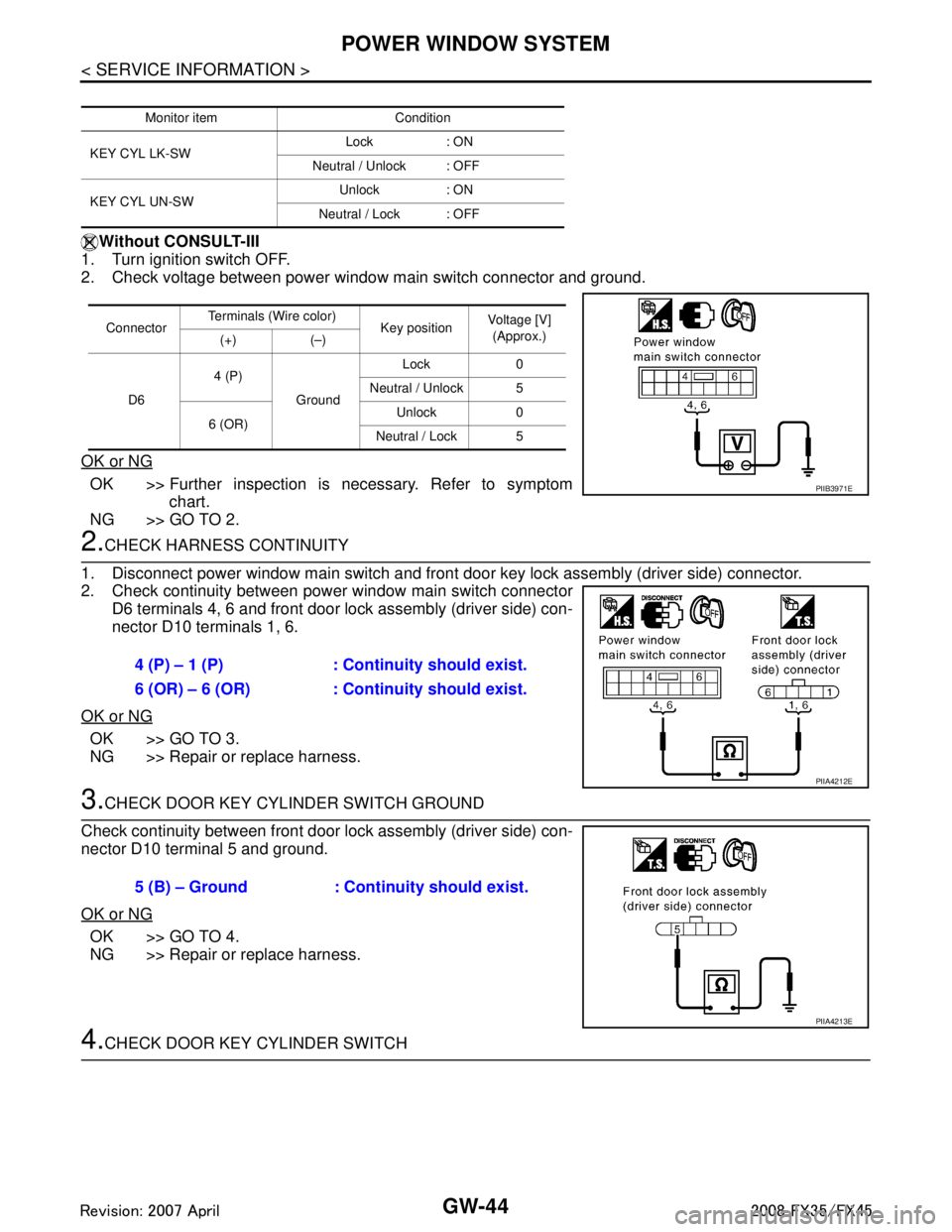
Without CONSULT-III
1. Turn ignition switch OFF.
2. Check voltage between power window main switch connector and ground.
OK or NG
OK >> Further inspection is necessary. Refer to symptom chart.
NG >> GO TO 2.
2.CHECK HARNESS CONTINUITY
1. Disconnect power window main switch and front door key lock assembly (driver side) connector.
2. Check continuity between power window main switch connector D6 terminals 4, 6 and front door lock assembly (driver side) con-
nector D10 terminals 1, 6.
OK or NG
OK >> GO TO 3.
NG >> Repair or replace harness.
3.CHECK DOOR KEY CYLINDER SWITCH GROUND
Check continuity between front door lock assembly (driver side) con-
nector D10 terminal 5 and ground.
OK or NG
OK >> GO TO 4.
NG >> Repair or replace harness.
4.CHECK DOOR KEY CYLINDER SWITCH
Monitor item Condition
KEY CYL LK-SW Lock : ON
Neutral / Unlock : OFF
KEY CYL UN-SW Unlock : ON
Neutral / Lock : OFF
Connector Terminals (Wire color)
Key position Voltage [V]
(Approx.)
(+) (–)
D6 4 (P)
Ground Lock 0
Neutral / Unlock 5
6 (OR) Unlock 0
Neutral / Lock 5
PIIB3971E
4 (P) – 1 (P) : Conti nuity should exist.
6 (OR) – 6 (OR) : Cont inuity should exist.
PIIA4212E
5 (B) – Ground : Continuity should exist.
PIIA4213E
3AA93ABC3ACD3AC03ACA3AC03AC63AC53A913A773A893A873A873A8E3A773A983AC73AC93AC03AC3
3A893A873A873A8F3A773A9D3AAF3A8A3A8C3A863A9D3AAF3A8B3A8C
Page 2958 of 3924

POWER WINDOW SYSTEMGW-45
< SERVICE INFORMATION >
C
DE
F
G H
J
K L
M A
B
GW
N
O P
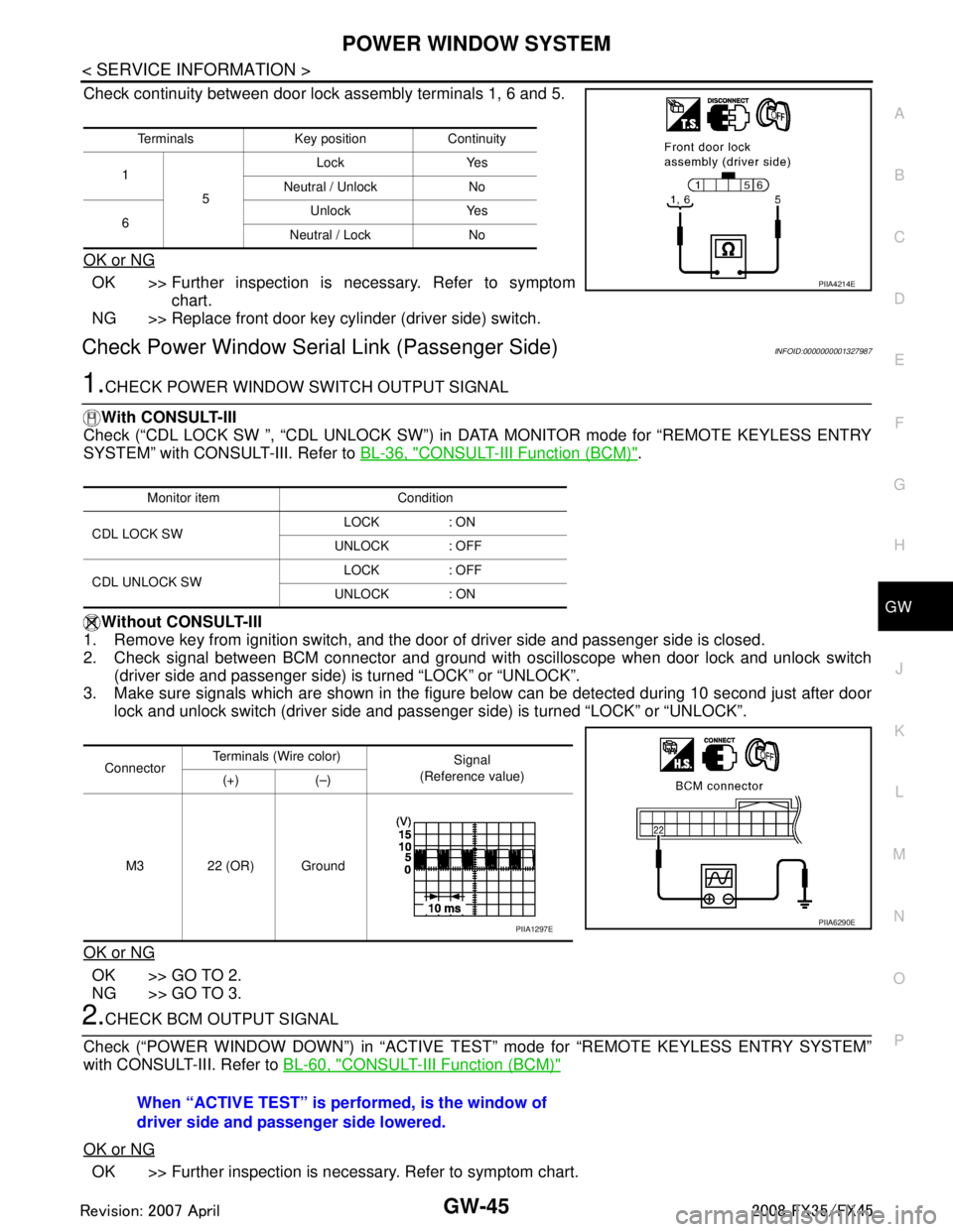
Check continuity between door lock assembly terminals 1, 6 and 5.
OK or NG
OK >> Further inspection is necessary. Refer to symptom chart.
NG >> Replace front door key cylinder (driver side) switch.
Check Power Window Serial Link (Passenger Side)INFOID:0000000001327987
1.CHECK POWER WINDOW SWITCH OUTPUT SIGNAL
With CONSULT-III
Check (“CDL LOCK SW ”, “CDL UNLOCK SW”) in DATA MONITOR mode for “REMOTE KEYLESS ENTRY
SYSTEM” with CONSULT-III. Refer to BL-36, "
CONSULT-III Function (BCM)".
Without CONSULT-III
1. Remove key from ignition switch, and the door of driver side and passenger side is closed.
2. Check signal between BCM connector and ground wit h oscilloscope when door lock and unlock switch
(driver side and passenger side) is turned “LOCK” or “UNLOCK”.
3. Make sure signals which are shown in the figure below can be detected during 10 second just after door
lock and unlock switch (driver side and passenger side) is turned “LOCK” or “UNLOCK”.
OK or NG
OK >> GO TO 2.
NG >> GO TO 3.
2.CHECK BCM OUTPUT SIGNAL
Check (“POWER WINDOW DOWN”) in “ACTIVE T EST” mode for “REMOTE KEYLESS ENTRY SYSTEM”
with CONSULT-III. Refer to BL-60, "
CONSULT-III Function (BCM)"
OK or NG
OK >> Further inspection is necessary. Refer to symptom chart.
Terminals Key position Continuity
1 5 Lock Yes
Neutral / Unlock No
6 Unlock Yes
Neutral / Lock No
PIIA4214E
Monitor item Condition
CDL LOCK SW LOCK : ON
UNLOCK : OFF
CDL UNLOCK SW LOCK : OFF
UNLOCK : ON
Connector Terminals (W
ire color)
Signal
(Reference value)
(+) (–)
M3 22 (OR) Ground
PIIA6290EPIIA1297E
When “ACTIVE TEST” is performed, is the window of
driver side and passenger side lowered.
3AA93ABC3ACD3AC03ACA3AC03AC63AC53A913A773A893A873A873A8E3A773A983AC73AC93AC03AC3
3A893A873A873A8F3A773A9D3AAF3A8A3A8C3A863A9D3AAF3A8B3A8C
Page 3021 of 3924

LAN-1
ELECTRICAL
C
DE
F
G H
I
J
L
M
SECTION LAN
A
B
LAN
N
O P
CONTENTS
LAN SYSTEM
CAN FUNDAMENTAL
SERVICE INFORMATION .. ..........................
3
PRECAUTIONS .............................................. .....3
Precaution for Trouble Diagnosis ........................ ......3
Precaution for Harness Repair ..................................3
SYSTEM DESCRIPTION .....................................4
CAN Communication System .............................. ......4
Diag on CAN .............................................................5
TROUBLE DIAGNOSIS ......................................7
Condition of Error Detection ................................ ......7
Symptom When Error Occurs in CAN Communi-
cation System ...................................................... ......
7
Self-Diagnosis .........................................................10
CAN Diagnostic Support Monitor ............................10
TROUBLE DIAGNOSES WORK FLOW ............13
Information Needed for Trouble Diagnosis ......... ....13
How to Use CAN Communication Signal Chart ......13
Trouble Diagnosis Flow Chart .................................14
Trouble Diagnosis Procedure ..................................14
CAN
SERVICE INFORMATION .. .........................
36
INDEX FOR DTC ............................................ ....36
DTC No. Index .................................................... ....36
HOW TO USE THIS SECTION ...........................37
Caution ................................................................ ....37
Abbreviation List ......................................................37
PRECAUTIONS ..................................................38
Precaution for Supplemental Restraint System
(SRS) "AIR BAG" and "SEAT BELT PRE-TEN-
SIONER" ............................................................. ....
38
Precaution for Trouble Diagnosis ............................38
Precaution for Harness Repair ................................38
TROUBLE DIAGNOSIS ....................................39
CAN Diagnostic Support Monitor ......................... ....39
CAN System Specification Chart .............................43
CAN Communication Signal Chart ..........................44
Schematic ................................................................54
Wiring Diagram - CAN - ...........................................55
Interview Sheet ........................................................58
Data Sheet ...............................................................58
CAN System (Type 1) ..............................................60
CAN System (Type 2) ..............................................61
CAN System (Type 3) ..............................................62
CAN System (Type 4) ..............................................63
CAN System (Type 5) ..............................................64
CAN System (Type 6) ..............................................65
CAN System (Type 7) ..............................................66
CAN system (Type 8) ..............................................67
Component Parts Location ......................................68
Harness Layout .......................................................68
Malfunction Area Chart ............................................68
Main Line Between TCM and Data Link Connector
....
69
Main Line Between Data Link Connector and Uni-
fied Meter and A/C Amp. .........................................
69
Main Line Between Unified Meter and A/C Amp.
and ABS Actuator and Electric Unit (Control Unit) ....
70
Main Line Between ABS Actu ator and Electric Unit
(Control Unit) and Driver Seat Control Unit .............
71
ECM Branch Line Circuit ..................................... ....72
AWD Control Unit Branch Line Circuit .....................72
Display Control Unit Branch Line Circuit .................73
ICC Unit Branch Line Circuit ................................ ....74
TCM Branch Line Circuit .........................................74
BCM Branch Line Circuit .........................................75
Data Link Connector Branch Line Circuit ................75
Intelligent Key Unit Branch Line Circuit ...................76
LDW Camera Unit Branch Line Circuit ....................76
Steering Angle Sensor Branch Line Circuit .............77
Unified Meter and A/C Amp. Branch Line Circuit ....78
ABS Actuator and Electric Unit (Control Unit)
Branch Line Circuit ..................................................
78
3AA93ABC3ACD3AC03ACA3AC03AC63AC53A913A773A893A873A873A8E3A773A983AC73AC93AC03AC3
3A893A873A873A8F3A773A9D3AAF3A8A3A8C3A863A9D3AAF3A8B3A8C
Page 3043 of 3924
![INFINITI FX35 2008 Service Manual
TROUBLE DIAGNOSES WORK FLOWLAN-23
< SERVICE INFORMATION > [CAN FUNDAMENTAL]
C
D
E
F
G H
I
J
L
M A
B
LAN
N
O P
c. Reception item of “AV”: “UNKWN” is not indicat ed. This indicates normal commu INFINITI FX35 2008 Service Manual
TROUBLE DIAGNOSES WORK FLOWLAN-23
< SERVICE INFORMATION > [CAN FUNDAMENTAL]
C
D
E
F
G H
I
J
L
M A
B
LAN
N
O P
c. Reception item of “AV”: “UNKWN” is not indicat ed. This indicates normal commu](/manual-img/42/57017/w960_57017-3042.png)
TROUBLE DIAGNOSES WORK FLOWLAN-23
< SERVICE INFORMATION > [CAN FUNDAMENTAL]
C
D
E
F
G H
I
J
L
M A
B
LAN
N
O P
c. Reception item of “AV”: “UNKWN” is not indicat ed. This indicates normal communication between AV and
its receiving units. Do not draw any line.
d. Reception item of “BCM”: On “TCM”, “UNKWN” is indicated. This means BCM cannot receive the signal
from TCM. Draw a line to indicate an error between BCM and TCM (line 2-d in the figure below).
e. Reception item of “EPS” and “I-KEY”: “UNKWN” is not indicated. This indicates normal communication
between EPS and I-KEY and their receiving units. Do not draw any line.
NOTE:
PKID1215E
3AA93ABC3ACD3AC03ACA3AC03AC63AC53A913A773A893A873A873A8E3A773A983AC73AC93AC03AC3
3A893A873A873A8F3A773A9D3AAF3A8A3A8C3A863A9D3AAF3A8B3A8C
Page 3057 of 3924
![INFINITI FX35 2008 Service Manual
HOW TO USE THIS SECTIONLAN-37
< SERVICE INFORMATION > [CAN]
C
D
E
F
G H
I
J
L
M A
B
LAN
N
O P
HOW TO USE THIS SECTION
CautionINFOID:0000000001328628
This section describes information peculiar to a INFINITI FX35 2008 Service Manual
HOW TO USE THIS SECTIONLAN-37
< SERVICE INFORMATION > [CAN]
C
D
E
F
G H
I
J
L
M A
B
LAN
N
O P
HOW TO USE THIS SECTION
CautionINFOID:0000000001328628
This section describes information peculiar to a](/manual-img/42/57017/w960_57017-3056.png)
HOW TO USE THIS SECTIONLAN-37
< SERVICE INFORMATION > [CAN]
C
D
E
F
G H
I
J
L
M A
B
LAN
N
O P
HOW TO USE THIS SECTION
CautionINFOID:0000000001328628
This section describes information peculiar to a v ehicle, sheets for trouble diagnosis, and inspection proce-
dures.
For trouble diagnosis procedure LAN-14, "
Trouble Diagnosis Procedure".
Abbreviation ListINFOID:0000000001328629
Abbreviations in CAN communication signal chart, and the diagnosis sheet are as per the following list.
Abbreviation Unit name SELECT SYSTEM
(CONSULT-III) CAN DIAG SUPPORT MNTR
(CONSULT-III)
4WD AWD control unit ALL MODE AWD/4WD AWD/4WD
A-BAG Air bag diagnosis sensor unit AIR BAG – ABS ABS actuator and electric un it (control unit) ABS VDC/TCS/ABS
ADP Driver seat control unit AUTO DRIVE POS. –
BCM BCM BCM BCM/SEC
DISP Display control unit – DISPLAY DLC Data link connector – –
ECM ECM ENGINE ECM
ICC ICC unit ICC ICC
ICC/e4WD
I-KEY Intelligent Key unit INTELLIGENT KEY I-KEY
IPDM-E IPDM E/R IPDM E/R IPDM E/R LANE LDW camera unit LDW –
LASER ICC sensor – ICC SENSOR M&A Unified meter and A/C amp. METER/M&A METER/M&A
STRG Steering angle sensor – STRG TCM TCM TRANSMISSION TCM
3AA93ABC3ACD3AC03ACA3AC03AC63AC53A913A773A893A873A873A8E3A773A983AC73AC93AC03AC3
3A893A873A873A8F3A773A9D3AAF3A8A3A8C3A863A9D3AAF3A8B3A8C
Page 3060 of 3924
![INFINITI FX35 2008 Service Manual
LAN-40
< SERVICE INFORMATION >[CAN]
TROUBLE DIAGNOSIS
TCM
NOTE:
Replace the unit when “NG” is i
ndicated on the “INITIAL DIAG”.
BCM
NOTE:
Replace the unit when “NG” is indicated on the � INFINITI FX35 2008 Service Manual
LAN-40
< SERVICE INFORMATION >[CAN]
TROUBLE DIAGNOSIS
TCM
NOTE:
Replace the unit when “NG” is i
ndicated on the “INITIAL DIAG”.
BCM
NOTE:
Replace the unit when “NG” is indicated on the �](/manual-img/42/57017/w960_57017-3059.png)
LAN-40
< SERVICE INFORMATION >[CAN]
TROUBLE DIAGNOSIS
TCM
NOTE:
Replace the unit when “NG” is i
ndicated on the “INITIAL DIAG”.
BCM
NOTE:
Replace the unit when “NG” is indicated on the “INITIAL DIAG”.
Intelligent Key Unit
ITEMCAN DIAG SUP-
PORT MNTR DescriptionNormal Error
PRSNT
ICC INITIAL DIAG Status of CAN controller
OKNG
TRANSMIT DIAG Signal transmission status
UNKWN
ECM Signal receiving status from the ECM
VDC/TCS/ABS
Signal receiving status from th
e ABS actuator and electric unit
(control unit)
TCM Signal receiving status from the TCM
METER/M&A Not used even though indicated
LANE KEEP
ECM(l)
ICC SENSOR Signal receiving status from the ICC sensor OK UNKWN
STRG
Not used even though indicated
METER/M&A(l)
ERROR(l)
LANE DETEC-
TOR
TCM(l)
BCM/SEC Signal receiving status from the BCM OK UNKWN
ITEM
CAN DIAG SUP-
PORT MNTR DescriptionNormal Error
PRSNT
TCM INITIAL DIAG Status of CAN controller
OKNG
TRANSMIT DIAG Signal transmission status
UNKWN
ECM Signal receiving status from the ECM
VDC/TCS/ABS
Signal receiving status from th
e ABS actuator and electric unit
(control unit)
METER/M&A Signal receiving status from the unified meter and A/C amp.
ICC/e4WD Signal receiving status from the ICC unit
AWD/4WD Signal receiving status from the AWD control unit
ITEM CAN DIAG SUP-
PORT MNTR DescriptionNormal Error
PRSNT
BCM INITIAL DIAG Status of CAN controller
OKNG
TRANSMIT DIAG Signal transmission status
UNKWN
ECM Signal receiving status from the ECM
IPDM E/R Signal receiving status from the IPDM E/R
METER/M&A Signal receiving status from the unified meter and A/C amp.
I-KEY Not used even though indicated
3AA93ABC3ACD3AC03ACA3AC03AC63AC53A913A773A893A873A873A8E3A773A983AC73AC93AC03AC3
3A893A873A873A8F3A773A9D3AAF3A8A3A8C3A863A9D3AAF3A8B3A8C
Page 3061 of 3924
![INFINITI FX35 2008 Service Manual
TROUBLE DIAGNOSISLAN-41
< SERVICE INFORMATION > [CAN]
C
D
E
F
G H
I
J
L
M A
B
LAN
N
O P
0: Error at present, 1 – 39: Error in the past (Number m eans the number of times the ignition switch is turn INFINITI FX35 2008 Service Manual
TROUBLE DIAGNOSISLAN-41
< SERVICE INFORMATION > [CAN]
C
D
E
F
G H
I
J
L
M A
B
LAN
N
O P
0: Error at present, 1 – 39: Error in the past (Number m eans the number of times the ignition switch is turn](/manual-img/42/57017/w960_57017-3060.png)
TROUBLE DIAGNOSISLAN-41
< SERVICE INFORMATION > [CAN]
C
D
E
F
G H
I
J
L
M A
B
LAN
N
O P
0: Error at present, 1 – 39: Error in the past (Number m eans the number of times the ignition switch is turned OFF →ON)
*: 39 or higher number is fixed at 39 until the self-diagnosis result is erased.
LDW Camera Unit
0: Error at present, 1 – 39: Error in the past (Number m eans the number of times the ignition switch is turned OFF →ON)
*: 39 or higher number is fixed at 39 until the self-diagnosis result is erased.
Unified Meter and A/C Amp.
0: Error at present, 1 – 39: Error in the past (Number m eans the number of times the ignition switch is turned OFF →ON)
*: 39 or higher number is fixed at 39 until the self-diagnosis result is erased.
ABS Actuator and Electric Unit (Control Unit)
ITEM CAN DIAG SUP-
PORT MNTR Description Normal Error
PRSNT PAST PRSNT PAST
I-KEY TRANSMIT DIAG Signal transmission status
OKOK
or
1 – 39
*UNKWN 0
ECM Signal receiving status from the ECM
METER/M&A
Signal receiving status from the unified
meter and A/C amp.
BCM/SEC Signal receiving status from the BCM
ITEM CAN DIAG SUP-
PORT MNTR Description Normal Error
PRSNT PAST PRSNT PAST
LKS TRANSMIT DIAG Not used even though indicated
ECM Signal receiving status from the ECM
OKOK
or
1 – 39
*UNKWN 0
VDC/TCS/ABS
Signal receiving status from the ABS actu-
ator and electric unit (control unit)
BCM/SEC Signal receiving status from the BCM
TCM Signal receiving status from the TCM
ITEM CAN DIAG SUP-
PORT MNTR Description Normal Error
PRSNT PAST PRSNT PAST
M&A TRANSMIT DIAG Signal transmission status
OKOK
or
1 – 39
*UNKWN 0
ECM Signal receiving status from the ECM
TCM Signal receiving status from the TCM
BCM/SEC Signal receiving status from the BCM
VDC/TCS/ABS
Signal receiving status from the ABS actu-
ator and electric unit (control unit)
IPDM E/R Not used even though indicated
DISPLAY Signal receiving status from the display
control unit
OKOK
or
1 – 39
*UNKWN 0
I-KEY Signal receiving status from the Intelligent
Key unit
EPS Not used even though indicated
AWD/4WD Signal receiving status from the AWD con-
trol unit OKOK
or
1 – 39
*UNKWN 0
e4WD Not used even though indicated
ICC Signal receiving status from the ICC unit OK OK
or
1 – 39
*UNKWN 0
LANE KEEP Not used even though indicated
TIRE-P
3AA93ABC3ACD3AC03ACA3AC03AC63AC53A913A773A893A873A873A8E3A773A983AC73AC93AC03AC3
3A893A873A873A8F3A773A9D3AAF3A8A3A8C3A863A9D3AAF3A8B3A8C
Page 3063 of 3924
![INFINITI FX35 2008 Service Manual
TROUBLE DIAGNOSISLAN-43
< SERVICE INFORMATION > [CAN]
C
D
E
F
G H
I
J
L
M A
B
LAN
N
O P
*: The error counter stops counting when it reaches “50” and holds “50” until it is deleted.
CAN System INFINITI FX35 2008 Service Manual
TROUBLE DIAGNOSISLAN-43
< SERVICE INFORMATION > [CAN]
C
D
E
F
G H
I
J
L
M A
B
LAN
N
O P
*: The error counter stops counting when it reaches “50” and holds “50” until it is deleted.
CAN System](/manual-img/42/57017/w960_57017-3062.png)
TROUBLE DIAGNOSISLAN-43
< SERVICE INFORMATION > [CAN]
C
D
E
F
G H
I
J
L
M A
B
LAN
N
O P
*: The error counter stops counting when it reaches “50” and holds “50” until it is deleted.
CAN System Specification ChartINFOID:0000000001328635
Determine CAN system type from the following specific ation chart. Then choose the correct diagnosis sheet.
NOTE:
Refer to LAN-14, "
Trouble Diagnosis Procedure" for how to use CAN system specification chart.
VEHICLE EQUIPMENT IDENTIFICATION INFORMATION
NOTE:
Unit name Diagnosis item Description Indicated items on CAN DIAG SUPPORT MONITOR
Normal Error
Result indi- cated Error
counter
(Reference) Result indi-
cated Error
counter
(Reference)
Display control
unit CAN_COMM Status of CAN controller
OK0
or
1 – 50* NG
1 – 50*
CAN_CIRC_1 Signal transmission status
UNKWN
CAN_CIRC_2 Signal receiving status from the
BCM
CAN_CIRC_3 Signal receiving status from the
ECM
CAN_CIRC_4 Not used even though indicated
CAN_CIRC_5 Signal receiving status from the uni-
fied meter and A/C amp. OK0
or
1 – 50* UNKWN 1 – 50*
CAN_CIRC_6 Not used even though indicated
CAN_CIRC_7 Signal receiving status from the
IPDM E/R
OK0
or
1 – 50* UNKWN 1 – 50*
CAN_CIRC_8 Not used even though indicated
CAN_CIRC_9
Body type Wagon
Axle 2WD AWD
Engine VQ35DE VK45DE
Transmission A/T
Brake control VDC
ICC system ×××
Intelligent Key system ×× ××××
Lane departure warning system ×××
CAN system type 12345678
Diagnosis sheet LAN-60
LAN-61LAN-62LAN-63LAN-64LAN-65LAN-66LAN-67
CAN communication signal chart “TYPE 1/TYPE 2” “TYPE 3” “TYPE 4/TYPE 5/
TYPE 7” “TYPE 6/
TYPE 8” “TYPE 4/
TYPE 5/
TYPE 7” “TYPE 6/
TYPE 8”
3AA93ABC3ACD3AC03ACA3AC03AC63AC53A913A773A893A873A873A8E3A773A983AC73AC93AC03AC3
3A893A873A873A8F3A773A9D3AAF3A8A3A8C3A863A9D3AAF3A8B3A8C