2008 INFINITI FX35 belt
[x] Cancel search: beltPage 3611 of 3924
SC-2
< SERVICE INFORMATION >
PRECAUTIONS
SERVICE INFORMATION
PRECAUTIONS
Precaution for Supplemental Restraint System (SRS) "AIR BAG" and "SEAT BELT
PRE-TENSIONER"
INFOID:0000000001612927
The Supplemental Restraint System such as “A IR BAG” and “SEAT BELT PRE-TENSIONER”, used along
with a front seat belt, helps to reduce the risk or severi ty of injury to the driver and front passenger for certain
types of collision. This system includes seat belt switch inputs and dual stage front air bag modules. The SRS
system uses the seat belt switches to determine the front air bag deployment, and may only deploy one front
air bag, depending on the severity of a collision and w hether the front occupants are belted or unbelted.
Information necessary to service the system safely is included in the “SUPPLEMENTAL RESTRAINT SYS-
TEM” and “SEAT BELTS” of this Service Manual.
WARNING:
• To avoid rendering the SRS inopera tive, which could increase the risk of personal injury or death in
the event of a collision which would result in air bag inflation, all maintenance must be performed by
an authorized NISS AN/INFINITI dealer.
Improper maintenance, including in correct removal and installation of the SRS, can lead to personal
injury caused by unintent ional activation of the system. For re moval of Spiral Cable and Air Bag
Module, see the “SUPPLEMEN TAL RESTRAINT SYSTEM”.
Do not use electrical test equipmen t on any circuit related to the SRS unless instructed to in this
Service Manual. SRS wiring harnesses can be identi fied by yellow and/or orange harnesses or har-
ness connectors.
3AA93ABC3ACD3AC03ACA3AC03AC63AC53A913A773A893A873A873A8E3A773A983AC73AC93AC03AC3
3A893A873A873A8F3A773A9D3AAF3A8A3A8C3A863A9D3AAF3A8B3A8C
Page 3632 of 3924
CHARGING SYSTEMSC-23
< SERVICE INFORMATION >
C
DE
F
G H
I
J
L
M A
B
SC
N
O P
Check if battery terminals are clean and tight.
OK or NG
OK >> GO TO 2.
NG >> Repair battery terminals connection.
2.CHECK FUSE AND FUSIBLE LINK
Check for blown alternator and combination meter fuses.
OK or NG
OK >> GO TO 3.
NG >> If fuse is blown, be sure eliminate cause of malfunction before installing new fuse.
3.CHECK “E” TERMINAL CONNECTION
Check if “E” terminal (alternator ground harness) is clean and tight.
OK or NG
OK >> GO TO 4.
NG >> Repair “E” terminal connection.
4.CHECK ALTERNATOR DRIVE BELT TENSION
Check alternator drive belt tension. Refer to EM-170, "
Checking Drive Belts" (VK45DE) or EM-14, "Checking
Drive Belts" (VQ35DE).
OK or NG
OK >> INSPECTION END
NG >> Repair as needed.
DIAGNOSTIC PROCEDURE 1
Check “L” Terminal Circuit (Open)
1.CHECK “L” TERMINAL CONNECTION
1. Turn ignition switch OFF.
2. Check if “L” terminal is clean and tight.
OK or NG
OK >> GO TO 2.
NG >> Repair “L” terminal connection. Confirm repa ir by performing complete Starting/Charging system
test. Refer to Technical Service Bulletin.
2.CHECK “L” TERMINAL CIRCUIT (OPEN)
1. Disconnect alternator connector.
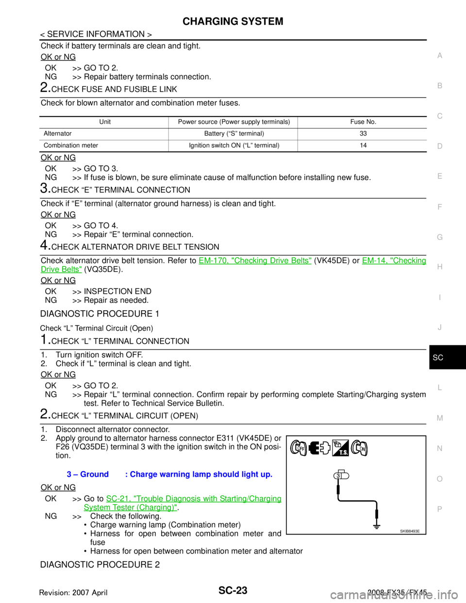
2. Apply ground to alternator harness connector E311 (VK45DE) or F26 (VQ35DE) terminal 3 with the ignition switch in the ON posi-
tion.
OK or NG
OK >> Go to SC-21, "Trouble Diagnosis with Starting/Charging
System Tester (Charging)".
NG >> Check the following. Charge warning lamp (Combination meter)
Harness for open between combination meter and
fuse
Harness for open between combination meter and alternator
DIAGNOSTIC PROCEDURE 2
Unit Power source (Power supply terminals) Fuse No.
Alternator Battery (“S” terminal) 33
Combination meter Ignition switch ON (“L” terminal) 14
3 – Ground : Charge warning lamp should light up.
SKIB8493E
3AA93ABC3ACD3AC03ACA3AC03AC63AC53A913A773A893A873A873A8E3A773A983AC73AC93AC03AC3
3A893A873A873A8F3A773A9D3AAF3A8A3A8C3A863A9D3AAF3A8B3A8C
Page 3635 of 3924
SC-26
< SERVICE INFORMATION >
CHARGING SYSTEM
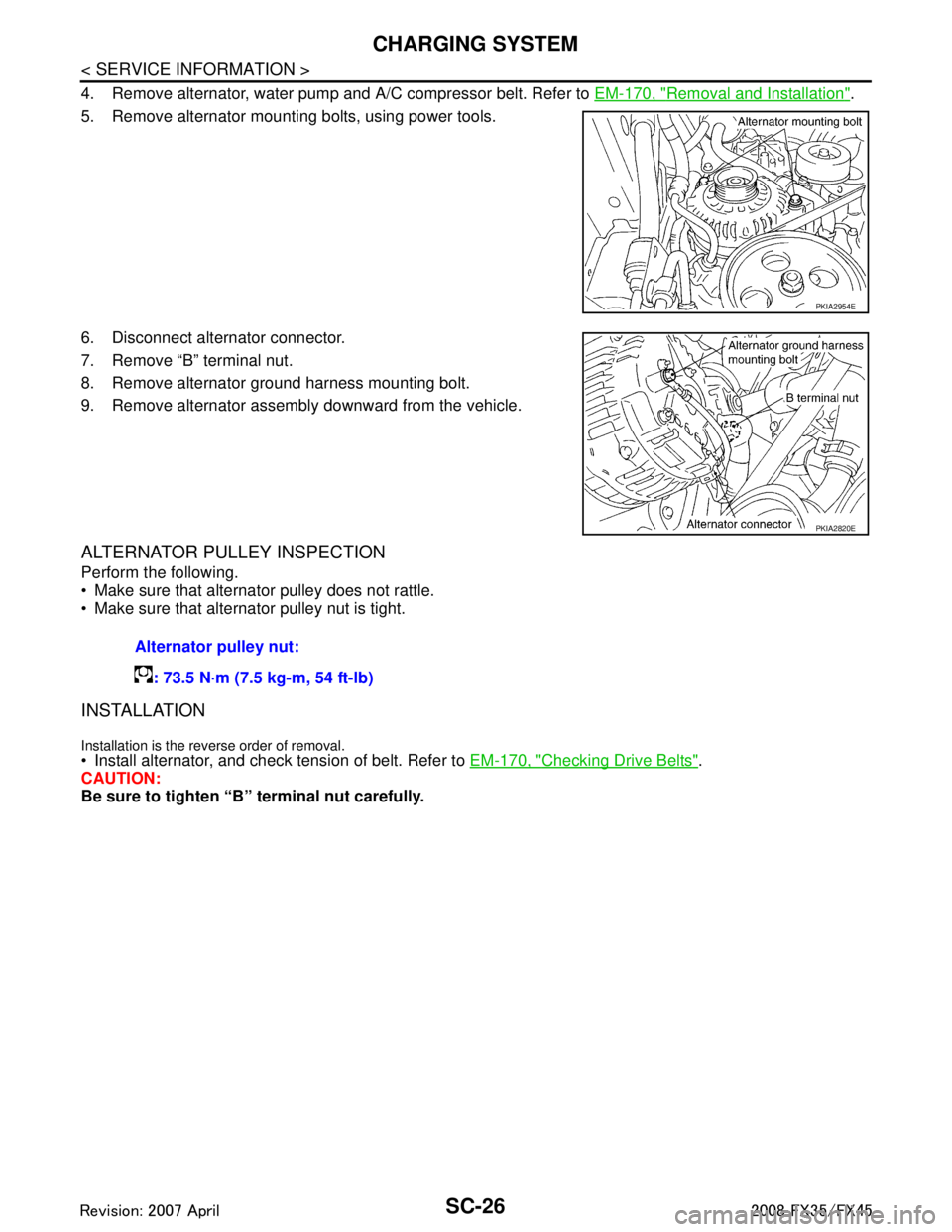
4. Remove alternator, water pump and A/C compressor belt. Refer to EM-170, "Removal and Installation".
5. Remove alternator mounting bolts, using power tools.
6. Disconnect alternator connector.
7. Remove “B” terminal nut.
8. Remove alternator ground harness mounting bolt.
9. Remove alternator assembly downward from the vehicle.
ALTERNATOR PULLEY INSPECTION
Perform the following.
Make sure that alternator pulley does not rattle.
Make sure that alternator pulley nut is tight.
INSTALLATION
Installation is the reverse order of removal. Install alternator, and check tension of belt. Refer to EM-170, "Checking Drive Belts".
CAUTION:
Be sure to tighten “B” terminal nut carefully.
PKIA2954E
PKIA2820E
Alternator pulley nut:
: 73.5 N·m (7.5 kg-m, 54 ft-lb)
3AA93ABC3ACD3AC03ACA3AC03AC63AC53A913A773A893A873A873A8E3A773A983AC73AC93AC03AC3
3A893A873A873A8F3A773A9D3AAF3A8A3A8C3A863A9D3AAF3A8B3A8C
Page 3636 of 3924
CHARGING SYSTEMSC-27
< SERVICE INFORMATION >
C
DE
F
G H
I
J
L
M A
B
SC
N
O P
Removal and Installation (VQ35DE Engine Models)INFOID:0000000001328258
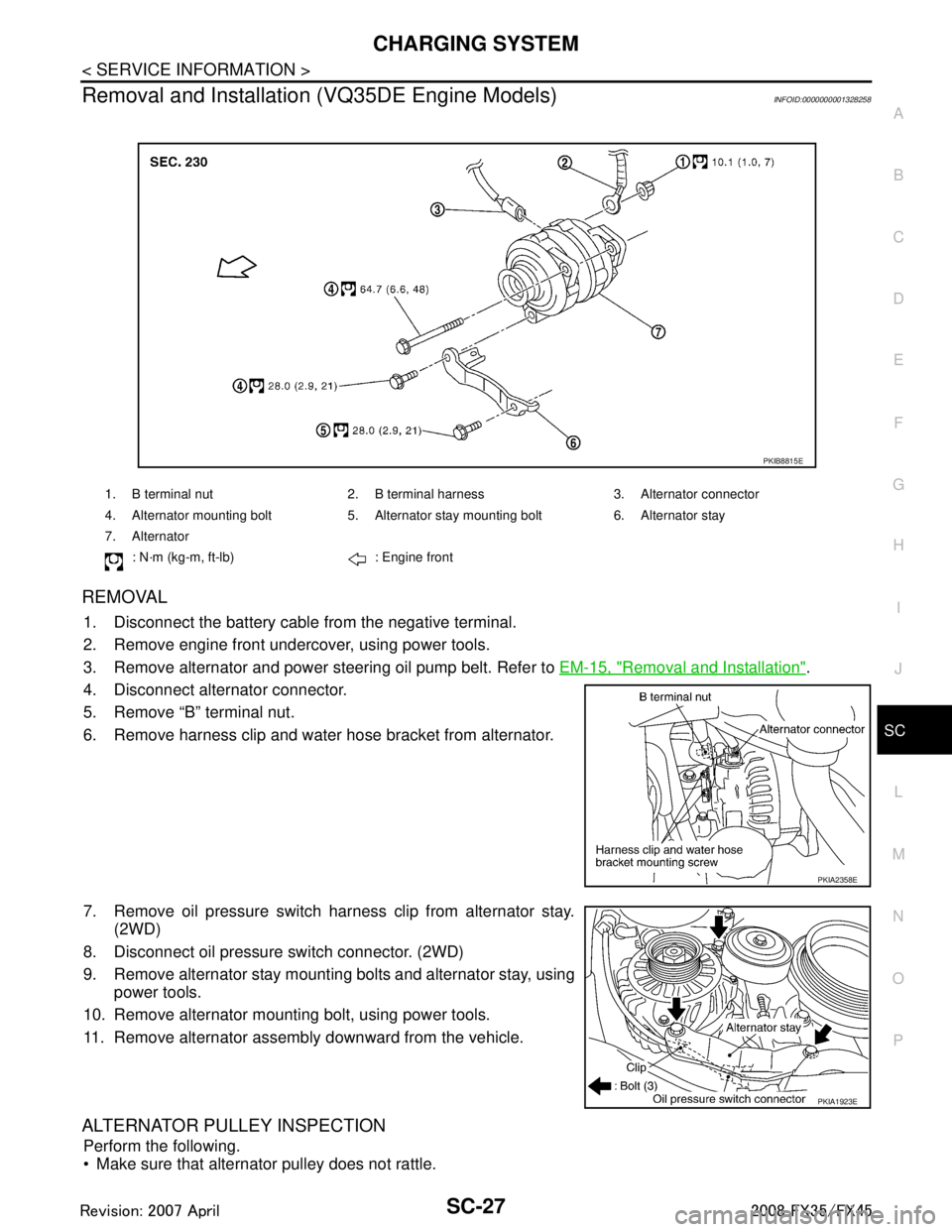
REMOVAL
1. Disconnect the battery cabl e from the negative terminal.
2. Remove engine front undercover, using power tools.
3. Remove alternator and power steering oil pump belt. Refer to EM-15, "
Removal and Installation".
4. Disconnect alternator connector.
5. Remove “B” terminal nut.
6. Remove harness clip and water hose bracket from alternator.
7. Remove oil pressure switch harness clip from alternator stay. (2WD)
8. Disconnect oil pressure switch connector. (2WD)
9. Remove alternator stay mounting bolts and alternator stay, using power tools.
10. Remove alternator mounting bolt, using power tools.
11. Remove alternator assembly downward from the vehicle.
ALTERNATOR PULLEY INSPECTION
Perform the following.
Make sure that alternator pulley does not rattle.
1. B terminal nut 2. B terminal harness 3. Alternator connector
4. Alternator mounting bolt 5. Alternator stay mounting bolt 6. Alternator stay
7. Alternator
: N·m (kg-m, ft-lb) : Engine front
PKIB8815E
PKIA2358E
PKIA1923E
3AA93ABC3ACD3AC03ACA3AC03AC63AC53A913A773A893A873A873A8E3A773A983AC73AC93AC03AC3
3A893A873A873A8F3A773A9D3AAF3A8A3A8C3A863A9D3AAF3A8B3A8C
Page 3637 of 3924
SC-28
< SERVICE INFORMATION >
CHARGING SYSTEM
Make sure that alternator pulley nut is tight.
INSTALLATION
Installation is the reverse order of removal.
Install alternator, and check tension of belt. Refer to EM-14, "Checking Drive Belts".
CAUTION:
Be sure to tighten “B” terminal nut carefully.
Disassembly and AssemblyINFOID:0000000001328259
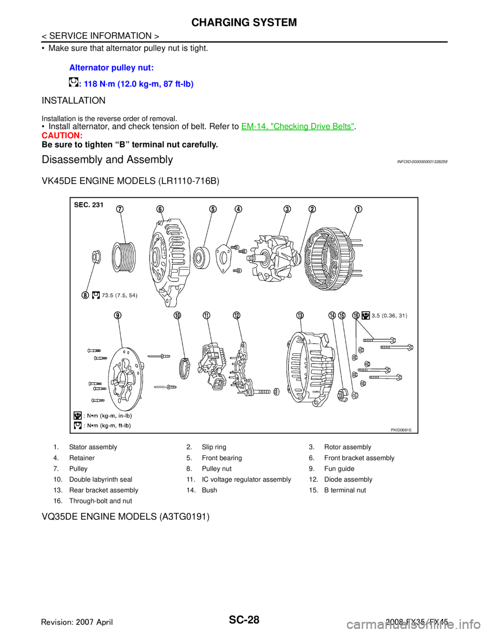
VK45DE ENGINE MODELS (LR1110-716B)
VQ35DE ENGINE MODELS (A3TG0191)
Alternator pulley nut:
: 118 N·m (12.0 kg-m, 87 ft-lb)
1. Stator assembly 2. Slip ring 3. Rotor assembly
4. Retainer 5. Front bearing 6. Front bracket assembly
7. Pulley 8. Pulley nut 9. Fun guide
10. Double labyrinth seal 11. IC voltage regulator assembly 12. Diode assembly
13. Rear bracket assembly 14. Bush 15. B terminal nut
16. Through-bolt and nut
PKID0691E
3AA93ABC3ACD3AC03ACA3AC03AC63AC53A913A773A893A873A873A8E3A773A983AC73AC93AC03AC3
3A893A873A873A8F3A773A9D3AAF3A8A3A8C3A863A9D3AAF3A8B3A8C
Page 3640 of 3924
SE-1
BODY
C
DE
F
G H
J
K L
M
SECTION SE
A
B
SE
N
O P
CONTENTS
SEAT
SERVICE INFORMATION .. ..........................3
DTC INDEX ..................................................... .....3
U1000 .................................................................. ......3
B2112-B2128 ............................................................3
PRECAUTIONS ...................................................4
Precaution for Supplemental Restraint System
(SRS) "AIR BAG" and "SEAT BELT PRE-TEN-
SIONER" ............................................................. ......
4
Service Notice ...........................................................4
PREPARATION ...................................................5
Special Service Tool ........................................... ......5
Commercial Service Tool ..........................................5
SQUEAK AND RATTLE TROUBLE DIAG-
NOSES ................................................................
6
Work Flow ........................................................... ......6
Generic Squeak and Rattle Troubleshooting ............8
Diagnostic Worksheet .............................................10
AUTOMATIC DRIVE POSITIONER ...................12
System Description ............................................. ....12
Component Parts and Harness Connector Loca-
tion ..........................................................................
16
CAN Communication System Description ...............17
CAN Communication Unit .......................................17
Schematic ...............................................................18
Wiring Diagram - AUT/DP - .....................................20
Terminal and Reference Value for BCM .................32
Terminal and Reference Value for Automatic
Drive Positioner Control Unit ...................................
32
Terminal and Reference Value for Driver Seat
Control Unit .............................................................
34
Work Flow ...............................................................37
Preliminary Check ...................................................37
CONSULT-III Function (AUTO DRIVE POS.) .........40
Check CAN Communication System ......................42
Symptom Chart .......................................................43
Check Sliding Motor Circuit .....................................44
Check Reclining Motor Circuit ............................. ....45
Check Front Lifting Motor Circuit .............................46
Check Rear Lifting Motor Circuit ..............................47
Check Telescopic Motor Circuit ...............................48
Check Tilt Motor Circuit ...........................................49
Check Driver Side Mirror Motor Circuit ....................50
Check Passenger Side Mirror Motor Circuit ............52
Check Sliding Sensor Circuit ...................................53
Check Reclining Sensor Circuit ...............................54
Check Front Lifting Sensor Circuit ...........................55
Check Rear Lifting Sensor Circuit ...........................56
Check Telescopic Sensor Circuit .............................57
Check Tilt Sensor Circuit .........................................58
Check Driver Side Mirror Sensor Circuit ..................59
Check Passenger Side Mirror Sensor Circuit ..........60
Check Steering and Door Mirror Sensor Power
Supply and Ground Circuit .................................. ....
61
Check Front Door Switch (Driver Side) Circuit ........62
Check Sliding Switch Circuit ....................................63
Check Reclining Switch Circuit ................................64
Check Front Lifting Switch Circuit ............................66
Check Rear Lifting Switch Circuit ............................67
Check Power Seat Switch Ground Circuit ...............68
Check Telescopic Switch Circuit .............................68
Check Tilt Switch Circuit ..........................................70
Check Door Mirror Remote Control Switch
(Changeover Switch) Circuit ................................ ....
71
Check Door Mirror Remote Control Switch (Mirror
Switch) Circuit ...................................................... ....
73
Check A/T Device (Park Position Switch) Circuit ....74
Check Key Switch Circuit (With Intelligent Key) ......76
Check Key Switch Circuit (Without Intelligent Key) ....77
Check Seat Memory Switch Circuit ..................... ....78
Check Seat Memory Indicator Lamp Circuit ............79
Check UART Communication Line Circuit ...............80
Check Lumbar Support Circuit ............................ ....82
POWER SEAT ...................................................84
Wiring Diagram - SEAT - .........................................84
HEATED SEAT .................................................86
3AA93ABC3ACD3AC03ACA3AC03AC63AC53A913A773A893A873A873A8E3A773A983AC73AC93AC03AC3
3A893A873A873A8F3A773A9D3AAF3A8A3A8C3A863A9D3AAF3A8B3A8C
Page 3643 of 3924
SE-4
< SERVICE INFORMATION >
PRECAUTIONS
PRECAUTIONS
Precaution for Supplemental Restraint System (SRS) "AIR BAG" and "SEAT BELT
PRE-TENSIONER"
INFOID:0000000001612906
The Supplemental Restraint System such as “A IR BAG” and “SEAT BELT PRE-TENSIONER”, used along
with a front seat belt, helps to reduce the risk or severi ty of injury to the driver and front passenger for certain
types of collision. This system includes seat belt switch inputs and dual stage front air bag modules. The SRS
system uses the seat belt switches to determine the front air bag deployment, and may only deploy one front
air bag, depending on the severity of a collision and w hether the front occupants are belted or unbelted.
Information necessary to service the system safely is included in the “SUPPLEMENTAL RESTRAINT SYS-
TEM” and “SEAT BELTS” of this Service Manual.
WARNING:
• To avoid rendering the SRS inopera tive, which could increase the risk of personal injury or death in
the event of a collision which would result in air bag inflation, all maintenance must be performed by
an authorized NISS AN/INFINITI dealer.
Improper maintenance, including in correct removal and installation of the SRS, can lead to personal
injury caused by unintent ional activation of the system. For re moval of Spiral Cable and Air Bag
Module, see the “SUPPLEMEN TAL RESTRAINT SYSTEM”.
Do not use electrical test equipmen t on any circuit related to the SRS unless instructed to in this
Service Manual. SRS wiring harnesses can be identi fied by yellow and/or orange harnesses or har-
ness connectors.
Service NoticeINFOID:0000000001328091
When removing or installing various parts, place a cloth or padding onto the vehicle body to prevent
scratches.
Handle trim, molding, instruments, grille, etc. carefull y during removing or installing. Be careful not to oil or
damage them.
Apply sealing compound where necessary when installing parts.
When applying sealing compound, be careful that the sealing compound does not protrude from parts.
When replacing any metal parts (for example body outer panel, members, etc.), be sure to take rust preven-
tion measures.
3AA93ABC3ACD3AC03ACA3AC03AC63AC53A913A773A893A873A873A8E3A773A983AC73AC93AC03AC3
3A893A873A873A8F3A773A9D3AAF3A8A3A8C3A863A9D3AAF3A8B3A8C
Page 3729 of 3924
SE-90
< SERVICE INFORMATION >
FRONT SEAT
REMOVAL
When removing or installing the seat trim, carefully handle it to keep dirt out and avoid damage.
CAUTION:
Before removing the front seat, turn ignition switch OFF, disconnect both battery cables and wait at
least 3 minutes.
When checking the power seat circuit for continuity using a circuit tester, do not confuse its connec-
tor with the side air bag modul e connector. Such an error may cause the air bag to deploy.
Do not drop, tilt, or bump the side air bag module installing in the seat. Always handle it with care.
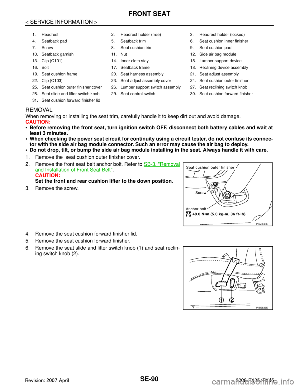
1. Remove the seat cushion outer finisher cover.
2. Remove the front seat belt anchor bolt. Refer to SB-3, "
Removal
and Installation of Front Seat Belt".
CAUTION:
Set the front and rear cushion lifter to the down position.
3. Remove the screw.
4. Remove the seat cushion forward finisher lid.
5. Remove the seat cushion forward finisher.
6. Remove the seat slide and lifter switch knob (1) and seat reclin- ing switch knob (2).
1. Headrest 2. Headrest holder (free) 3. Headrest holder (locked)
4. Seatback pad 5. Seatback trim 6. Seat cushion inner finisher
7. Screw 8. Seat cushion trim 9. Seat cushion pad
10. Seatback garnish 11. Nut 12. Side air bag module
13. Clip (C101) 14. Inner cloth stay 15. Lumber support device
16. Bolt 17. Seatback frame 18. Reclining device assembly
19. Seat cushion frame 20. Seat harness assembly 21. Seat adjust assembly
22. Clip (C103) 23. Seat adjust assembly cover 24. Seat cushion outer finisher
25. Seat cushion outer finisher cover 26. Lumber support switch assembly 27. Seat reclining switch knob
28. Seat slide and lifter switch knob 29. Seat control switch 30. Seat cushion forward finisher
31. Seat cushion forward finisher lid
PIIA6040E
PIIB8525E
3AA93ABC3ACD3AC03ACA3AC03AC63AC53A913A773A893A873A873A8E3A773A983AC73AC93AC03AC3
3A893A873A873A8F3A773A9D3AAF3A8A3A8C3A863A9D3AAF3A8B3A8C