2008 INFINITI FX35 ECU
[x] Cancel search: ECUPage 989 of 3924

BRAKE PEDALBR-5
< SERVICE INFORMATION >
C
DE
G H
I
J
K L
M A
B
BR
N
O P
BRAKE PEDAL
Inspection and AdjustmentINFOID:0000000001327607
Play and clearance between brake pedal and floor panel with pedal depressed
1. Check brake pedal height from dash lower panel.
2. Adjust height referring to the following specifications.
ADJUSTMENT
1. Loosen stop lamp switch and ASCD cancel switch (or brake switch) by rotating it counterclockwise by 45 °.
2. Loosen lock nut (A) on input rod, then rotate input rod to set pedal to the specified height, and tighten lock nut (A). Refer to
BR-14, "
Component".
CAUTION:
Make sure the threaded end of input rod stays inside clevis.
3. With pedal pulled and held by hand, press stop lamp switch and ASCD cancel switch (or brake switch) until its threaded end con-
tacts stopper rubber.
4. With the threaded end of stop lamp switch and ASCD cancel switch (or brake switch) contacting stopper rubber, rotate switch
clockwise by 45 ° to secure.
CAUTION:
Make sure that the clearance “C” between stopper rubber
and threaded end of stop lamp switch and ASCD cancel
switch (or brake switch) is within the standard.
5. Check pedal play. CAUTION:
Make sure that stop lamps go off when pedal is released.
6. Start engine to check brake pedal depressed height.
H Brake pedal height (from dash low-
er panel top surface) 161.5
− 171.5 mm (6.358 − 6.752 in)
D Depressed pedal height [under a
force of 490 N (50 kg, 110 lb) with
engine running] More than 95 mm (3.74 in)
C Clearance between stopper rubber
and the threaded end of stop lamp
switch and ASCD cancel switch (or
brake switch) 0.74
− 1.96 mm (0.0291 −0.0772 in)
A Pedal play 3 − 11 mm (0.12 − 0.43 in)
SFIA2380E
PFIA0819E
3AA93ABC3ACD3AC03ACA3AC03AC63AC53A913A773A893A873A873A8E3A773A983AC73AC93AC03AC3
3A893A873A873A8F3A773A9D3AAF3A8A3A8C3A863A9D3AAF3A8B3A8C
Page 994 of 3924

BR-10
< SERVICE INFORMATION >
BRAKE TUBE AND HOSE
BRAKE TUBE AND HOSE
Hydraulic CircuitINFOID:0000000001327613
CAUTION:
All brake hoses and tubes must be free from excessive bending, twisting and pulling.
Make sure there is no interference with other part s when turning steering both clockwise and coun-
terclockwise.
The brake tubes and hoses is an important safety pa rt. If a brake fluid leak is detected, always disas-
semble the parts. Replace applicable part with a new one, if necessary.
Be careful not to splash brake fluid on painted areas; it way cause paint damage. If brake fluid is
splashed on painted surfaces of bo dy, immediately wipe it off and them wash it away with water
immediately.
Do not bend or twist brake hose sharply, or strongly pull it.
When removing components, cover br ake line connections so that no dirt, no dust, or other foreign
matter gets in.
Refill with new brake fluid “ DOT 3 ”.
Do not reuse drained brake fluid.
Removal and Installation of Fr ont Brake Tube and Brake HoseINFOID:0000000001327614
REMOVAL
1. Drain brake fluid. Refer to BR-8, "Drain and Refill".
2. Using a flare nut wrench, remove brake tube from brake hose.
3. Remove union bolt and remove brake hose from caliper assembly.
4. Remove lock plate and remove brake hose from vehicle.
INSTALLATION
1. Position brake hose by aligning with the protrusion on caliper assembly, and them tighten union bolt to the specified torque.
CAUTION:
Do not reuse copper washer.
2. Install brake hose to brake tube. Temporarily tighten flare nut by hand as much as possible. Secure them it to bracket with lock
plate.
3. Using a flare nut torque wrench, tighten flare nut to the specified
torque.
4. Refill brake fluid and bleed air. Refer to BR-8, "
Bleeding Brake
System".
PFIA0818E
SFIA1204E
3AA93ABC3ACD3AC03ACA3AC03AC63AC53A913A773A893A873A873A8E3A773A983AC73AC93AC03AC3
3A893A873A873A8F3A773A9D3AAF3A8A3A8C3A863A9D3AAF3A8B3A8C
Page 1003 of 3924
FRONT DISC BRAKEBR-19
< SERVICE INFORMATION >
C
DE
G H
I
J
K L
M A
B
BR
N
O P
While removing cylinder body, never depr ess brake pedal because piston will pop out.
It is not necessary to remove bolts on torq ue member and brake hose except for disassembly or
replacement of caliper assembly. In this case, suspe nd cylinder body with wire so as not to stretch
brake hose.
Do not damage piston boot.
If any shim is subject to serious corrosion, replace it with a new one.
Always replace shims and shim covers as a set when replacing brake pads.
Keep rotor clean, from brake fluid.
Burnish brake contact surface after refinishing or replacing rotors, after replacing pads, or it a soft
pedal occurs at very low mileage. Refer to BR-23, "
Brake Burnishing Procedure".
Removal and Installation of Brake PadINFOID:0000000001327629
REMOVAL
1. Remove tires from vehicle with power tool.
2. Remove lower sliding pin bolt.
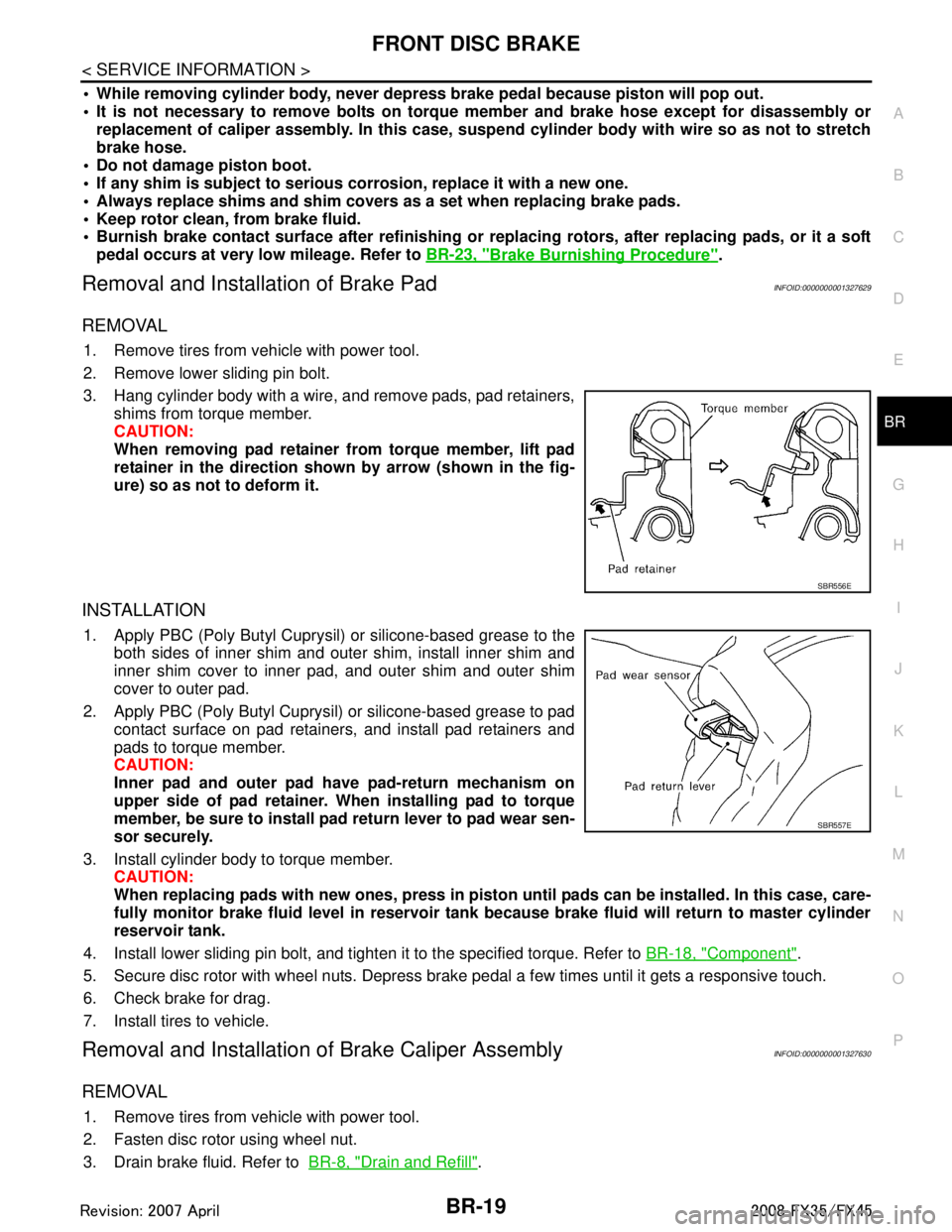
3. Hang cylinder body with a wire, and remove pads, pad retainers,
shims from torque member.
CAUTION:
When removing pad retainer from torque member, lift pad
retainer in the direction show n by arrow (shown in the fig-
ure) so as not to deform it.
INSTALLATION
1. Apply PBC (Poly Butyl Cuprysil) or silicone-based grease to the both sides of inner shim and outer shim, install inner shim and
inner shim cover to inner pad, and outer shim and outer shim
cover to outer pad.
2. Apply PBC (Poly Butyl Cuprysil) or silicone-based grease to pad contact surface on pad retainers, and install pad retainers and
pads to torque member.
CAUTION:
Inner pad and outer pad have pad-return mechanism on
upper side of pad retainer. When installing pad to torque
member, be sure to install pad return lever to pad wear sen-
sor securely.
3. Install cylinder body to torque member. CAUTION:
When replacing pads with new ones, press in piston until pads can be installed. In this case, care-
fully monitor brake fluid level in reservoir tank because brake fluid will return to master cylinder
reservoir tank.
4. Install lower sliding pin bolt, and tighten it to the specified torque. Refer to BR-18, "
Component".
5. Secure disc rotor with wheel nuts. Depress brake pedal a few times until it gets a responsive touch.
6. Check brake for drag.
7. Install tires to vehicle.
Removal and Installation of Brake Caliper AssemblyINFOID:0000000001327630
REMOVAL
1. Remove tires from vehicle with power tool.
2. Fasten disc rotor using wheel nut.
3. Drain brake fluid. Refer to BR-8, "
Drain and Refill".
SBR556E
SBR557E
3AA93ABC3ACD3AC03ACA3AC03AC63AC53A913A773A893A873A873A8E3A773A983AC73AC93AC03AC3
3A893A873A873A8F3A773A9D3AAF3A8A3A8C3A863A9D3AAF3A8B3A8C
Page 1004 of 3924
BR-20
< SERVICE INFORMATION >
FRONT DISC BRAKE
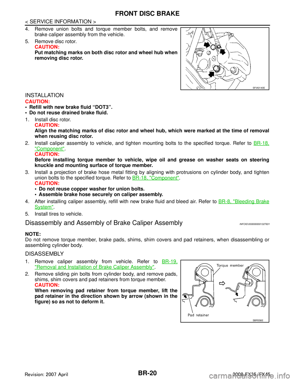
4. Remove union bolts and torque member bolts, and removebrake caliper assembly from the vehicle.
5. Remove disc rotor. CAUTION:
Put matching marks on both disc rotor and wheel hub when
removing disc rotor.
INSTALLATION
CAUTION:
Refill with new brake fluid “DOT3”.
Do not reuse drained brake fluid.
1. Install disc rotor.
CAUTION:
Align the matching marks of disc rotor and wheel hub, which were marked at the time of removal
when reusing disc rotor.
2. Install caliper assembly to vehicle, and tighten mounting bolts to the specified torque. Refer to BR-18,
"Component".
CAUTION:
Before installing torque member to vehicle, wipe oil and grease on washer seats on steering
knuckle and mounting surface of torque member.
3. Install a projection of brake hose metal fitting by aligning with protrusions on cylinder body, and tighten
union bolts to the specified torque. Refer to BR-18, "
Component".
CAUTION:
Do not reuse copper washer for union bolts.
Assemble brake hose securely on caliper assembly.
4. After installing caliper assembly, refill with new brake fluid and bleed air. Refer to BR-8, "
Bleeding Brake
System".
5. Install tires to vehicle.
Disassembly and Assembly of Brake Caliper AssemblyINFOID:0000000001327631
NOTE:
Do not remove torque member, brake pads, shims, shim covers and pad retainers, when disassembling or
assembling cylinder body.
DISASSEMBLY
1. Remove caliper assembly from vehicle. Refer to BR-19,
"Removal and Installation of Brake Caliper Assembly".
2. Remove sliding pin bolts from cylinder body, and remove pads, shims, shim covers and pad retainers from torque member.
CAUTION:
When removing pad retainer fr om torque member, lift the
pad retainer in the direction shown by arrow (shown in the
figure) so as not to deform it.
SFIA0140E
SBR556E
3AA93ABC3ACD3AC03ACA3AC03AC63AC53A913A773A893A873A873A8E3A773A983AC73AC93AC03AC3
3A893A873A873A8F3A773A9D3AAF3A8A3A8C3A863A9D3AAF3A8B3A8C
Page 1006 of 3924
BR-22
< SERVICE INFORMATION >
FRONT DISC BRAKE
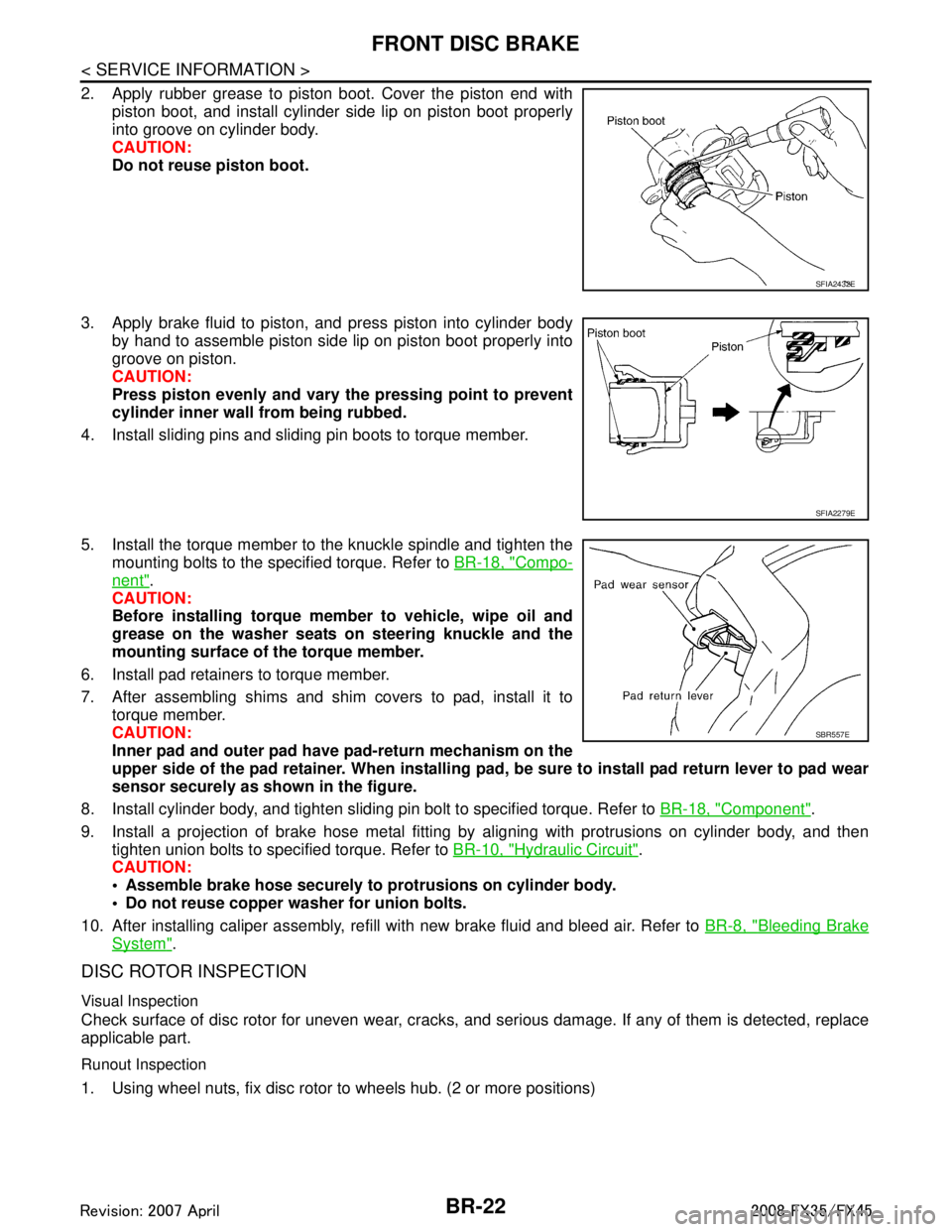
2. Apply rubber grease to piston boot. Cover the piston end withpiston boot, and install cylinder side lip on piston boot properly
into groove on cylinder body.
CAUTION:
Do not reuse piston boot.
3. Apply brake fluid to piston, and press piston into cylinder body by hand to assemble piston side lip on piston boot properly into
groove on piston.
CAUTION:
Press piston evenly and vary the pressing point to prevent
cylinder inner wall from being rubbed.
4. Install sliding pins and sliding pin boots to torque member.
5. Install the torque member to the knuckle spindle and tighten the mounting bolts to the specified torque. Refer to BR-18, "
Compo-
nent".
CAUTION:
Before installing torque member to vehicle, wipe oil and
grease on the washer seats on steering knuckle and the
mounting surface of the torque member.
6. Install pad retainers to torque member.
7. After assembling shims and shim covers to pad, install it to torque member.
CAUTION:
Inner pad and outer pad have pad-return mechanism on the
upper side of the pad retainer. When installing pad, be sure to install pad return lever to pad wear
sensor securely as shown in the figure.
8. Install cylinder body, and tighten sliding pin bolt to specified torque. Refer to BR-18, "
Component".
9. Install a projection of brake hose metal fitting by aligning with protrusions on cylinder body, and then tighten union bolts to specified torque. Refer to BR-10, "
Hydraulic Circuit".
CAUTION:
Assemble brake hose securely to protrusions on cylinder body.
Do not reuse copper washer for union bolts.
10. After installing caliper assembly, refill with new brake fluid and bleed air. Refer to BR-8, "
Bleeding Brake
System".
DISC ROTOR INSPECTION
Visual Inspection
Check surface of disc rotor for uneven wear, cracks, and serious damage. If any of them is detected, replace
applicable part.
Runout Inspection
1. Using wheel nuts, fix disc rotor to wheels hub. (2 or more positions)
SFIA2432E
SFIA2279E
SBR557E
3AA93ABC3ACD3AC03ACA3AC03AC63AC53A913A773A893A873A873A8E3A773A983AC73AC93AC03AC3
3A893A873A873A8F3A773A9D3AAF3A8A3A8C3A863A9D3AAF3A8B3A8C
Page 1007 of 3924
FRONT DISC BRAKEBR-23
< SERVICE INFORMATION >
C
DE
G H
I
J
K L
M A
B
BR
N
O P
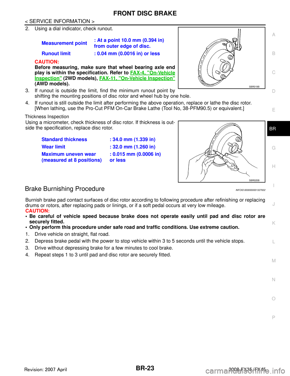
2. Using a dial indicator, check runout.
CAUTION:
Before measuring, make sure that wheel bearing axle end
play is within the sp ecification. Refer to FA X - 4 , "
On-Vehicle
Inspection" (2WD models), FA X - 11 , "On-Vehicle Inspection"
(AWD models).
3. If runout is outside the limit, find the minimum runout point by shifting the mounting positions of disc rotor and wheel hub by one hole.
4. If runout is still outside the limit after performing the above operation, replace or lathe the disc rotor.
[When lathing, use the Pro-Cut PFM On-Car Br ake Lathe (Tool No, 38-PFM90.5) or equivalent.]
Thickness Inspection
Using a micrometer, check thickness of disc rotor. If thickness is out-
side the specification, replace disc rotor.
Brake Burnishing ProcedureINFOID:0000000001327632
Burnish brake pad contact surfaces of disc rotor according to following procedure after refinishing or replacing
drums or rotors, after replacing pads or linings, or if a soft pedal occurs at very low mileage.
CAUTION:
Be careful of vehicle speed because brake does no t operate easily until pad and disc rotor are
securely fitted.
Only perform this procedure under safe road and traffic conditions. Use extreme caution.
1. Drive vehicle on straight, flat road.
2. Depress brake pedal with the power to stop vehicl e within 3 to 5 seconds until the vehicle stops.
3. Drive without depressing brake for a few minutes to cool brake.
4. Repeat steps 1 to 3 until pad and disc rotor are securely fitted. Measurement point
: At a point 10.0 mm (0.394 in)
from outer edge of disc.
Runout limit : 0.04 mm (0.0016 in) or less
SBR019B
Standard thickness : 34.0 mm (1.339 in)
Wear limit : 32.0 mm (1.260 in)
Maximum uneven wear
(measured at 8 positions) : 0.015 mm (0.0006 in)
or less
SBR020B
3AA93ABC3ACD3AC03ACA3AC03AC63AC53A913A773A893A873A873A8E3A773A983AC73AC93AC03AC3
3A893A873A873A8F3A773A9D3AAF3A8A3A8C3A863A9D3AAF3A8B3A8C
Page 1010 of 3924
BR-26
< SERVICE INFORMATION >
REAR DISC BRAKE
CAUTION:
Refill with new brake fluid “DOT 3”.
Do not reuse drained brake fluid.
1. Install disc rotor.CAUTION:
Align the matching marks of disc rotor and wheel hub, which were marked at the time of removal
when reusing disc rotor.
2. Install caliper assembly to the vehicle, and tighten bolts to the specified torque. Refer to BR-24, "
Compo-
nent".
CAUTION:
Before installing caliper assembly to the vehicle , wipe off oil and grease on washer seats on axle
assembly and mounting surface of caliper assembly.
3. Install brake hose to caliper assembly and tighten union bolt to the specified torque. Refer to BR-24,
"Component".
CAUTION:
Do not reuse copper washer for union bolts.
Securely install brake hose to protrusion on caliper assembly.
4. After installing caliper assembly, refill with new brake fluid and bleed air. Refer to BR-8, "
Bleeding Brake
System".
5. Install tires to the vehicle.
Disassembly and Assembly of Brake Caliper AssemblyINFOID:0000000001327637
NOTE:
Do not remove torque member, brake pads, shims, shim cover and pad retainers, when disassembling or
assembling cylinder body.
DISASSEMBLY
1. Remove sliding pin bolts, and then remove brake pads, shims, shim cover, and pad retainer from torque
member and cylinder.
CAUTION:
Do not drop brake pads, shims, shim cover and pad retainer from torque member.
2. Remove sliding pin boot from torque member.
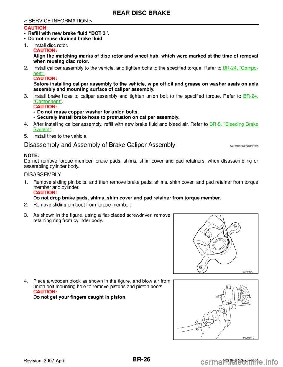
3. As shown in the figure, using a flat-bladed screwdriver, remove retaining ring from cylinder body.
4. Place a wooden block as shown in the figure, and blow air from union bolt mounting hole to remove pistons and piston boots.
CAUTION:
Do not get your fingers caught in piston.
SBR028A
BRD0041D
3AA93ABC3ACD3AC03ACA3AC03AC63AC53A913A773A893A873A873A8E3A773A983AC73AC93AC03AC3
3A893A873A873A8F3A773A9D3AAF3A8A3A8C3A863A9D3AAF3A8B3A8C
Page 1013 of 3924
REAR DISC BRAKEBR-29
< SERVICE INFORMATION >
C
DE
G H
I
J
K L
M A
B
BR
N
O P
4. If runout is still outside the limit after performing the above operation, replace or lathe the disc rotor.
[When lathing, use the Pro-Cut PFM On-Car Br ake Lathe (Tool No, 38-PFM90.5) or equivalent.]
Thickness Inspection
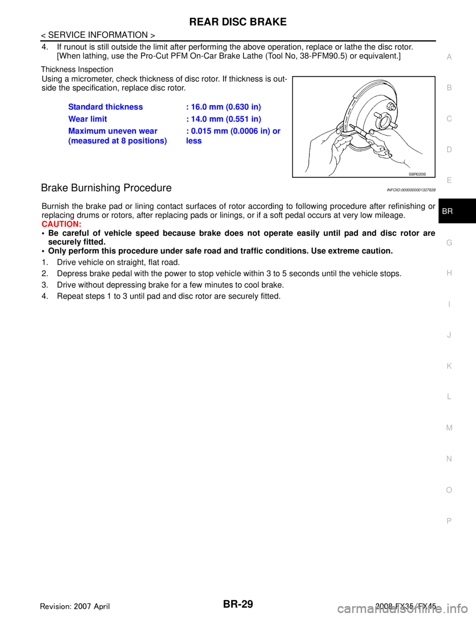
Using a micrometer, check thickness of disc rotor. If thickness is out-
side the specification, replace disc rotor.
Brake Burnishing ProcedureINFOID:0000000001327638
Burnish the brake pad or lining contact surfaces of rotor according to following procedure after refinishing or
replacing drums or rotors, after replacing pads or li nings, or if a soft pedal occurs at very low mileage.
CAUTION:
Be careful of vehicle speed because brake does no t operate easily until pad and disc rotor are
securely fitted.
Only perform this procedure under safe road and traffic conditions. Use extreme caution.
1. Drive vehicle on straight, flat road.
2. Depress brake pedal with the power to stop vehicl e within 3 to 5 seconds until the vehicle stops.
3. Drive without depressing brake for a few minutes to cool brake.
4. Repeat steps 1 to 3 until pad and disc rotor are securely fitted. Standard thickness : 16.0 mm (0.630 in)
Wear limit : 14.0 mm (0.551 in)
Maximum uneven wear
(measured at 8 positions)
: 0.015 mm (0.0006 in) or
less
SBR020B
3AA93ABC3ACD3AC03ACA3AC03AC63AC53A913A773A893A873A873A8E3A773A983AC73AC93AC03AC3
3A893A873A873A8F3A773A9D3AAF3A8A3A8C3A863A9D3AAF3A8B3A8C