2008 INFINITI FX35 ignition
[x] Cancel search: ignitionPage 3532 of 3924
SUNROOFRF-17
< SERVICE INFORMATION >
C
DE
F
G H
J
K L
M A
B
RF
N
O P
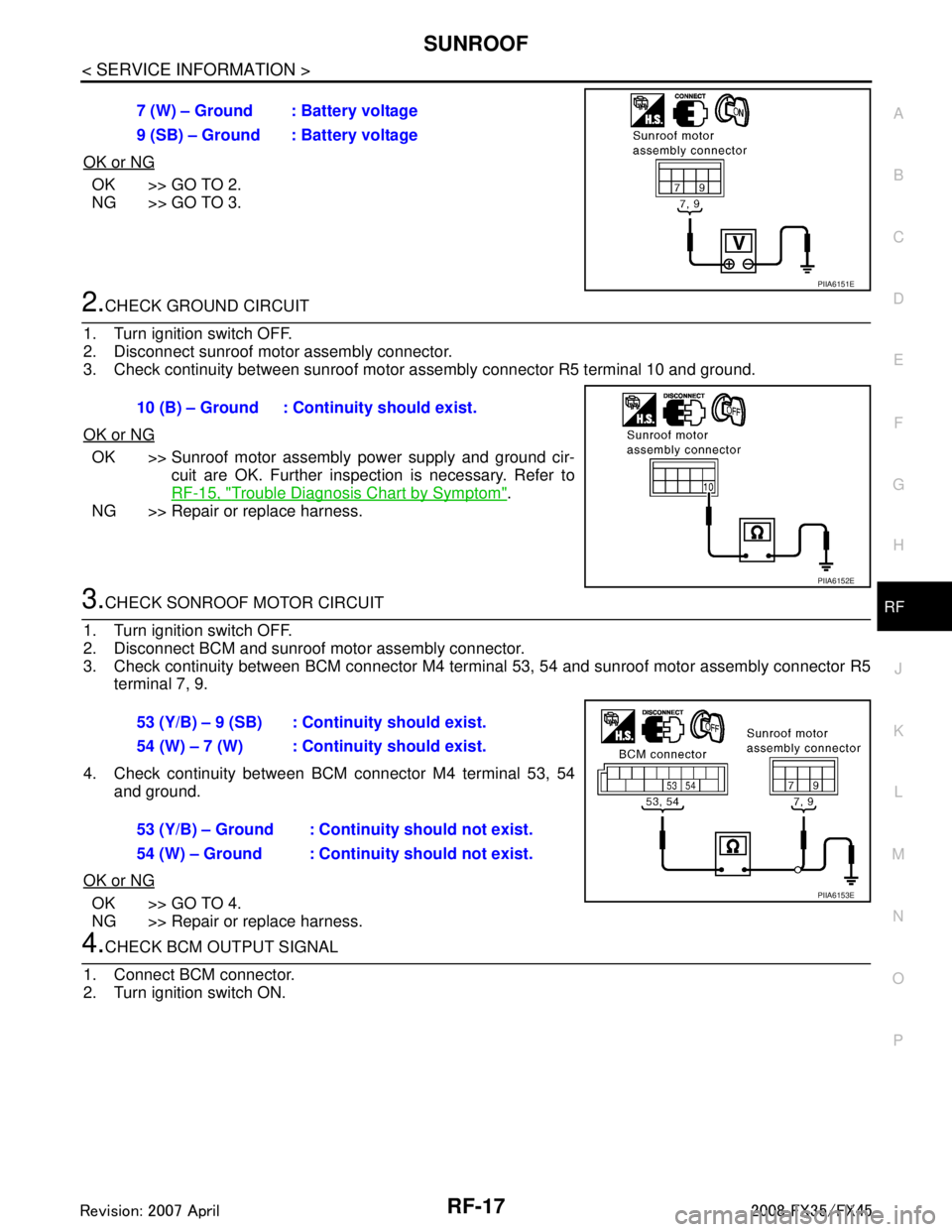
OK or NG
OK >> GO TO 2.
NG >> GO TO 3.
2.CHECK GROUND CIRCUIT
1. Turn ignition switch OFF.
2. Disconnect sunroof motor assembly connector.
3. Check continuity between sunroof motor assembly connector R5 terminal 10 and ground.
OK or NG
OK >> Sunroof motor assembly power supply and ground cir- cuit are OK. Further inspection is necessary. Refer to
RF-15, "
Trouble Diagnosis Chart by Symptom".
NG >> Repair or replace harness.
3.CHECK SONROOF MOTOR CIRCUIT
1. Turn ignition switch OFF.
2. Disconnect BCM and sunroof motor assembly connector.
3. Check continuity between BCM connector M4 terminal 53, 54 and sunroof motor assembly connector R5 terminal 7, 9.
4. Check continuity between BCM connector M4 terminal 53, 54 and ground.
OK or NG
OK >> GO TO 4.
NG >> Repair or replace harness.
4.CHECK BCM OUTPUT SIGNAL
1. Connect BCM connector.
2. Turn ignition switch ON. 7 (W) – Ground : Battery voltage
9 (SB) – Ground : Battery voltage
PIIA6151E
10 (B) – Ground : Continuity should exist.
PIIA6152E
53 (Y/B) – 9 (SB) : Cont
inuity should exist.
54 (W) – 7 (W) : Cont inuity should exist.
53 (Y/B) – Ground : Continuity should not exist.
54 (W) – Ground : Continuity should not exist.
PIIA6153E
3AA93ABC3ACD3AC03ACA3AC03AC63AC53A913A773A893A873A873A8E3A773A983AC73AC93AC03AC3
3A893A873A873A8F3A773A9D3AAF3A8A3A8C3A863A9D3AAF3A8B3A8C
Page 3533 of 3924
RF-18
< SERVICE INFORMATION >
SUNROOF
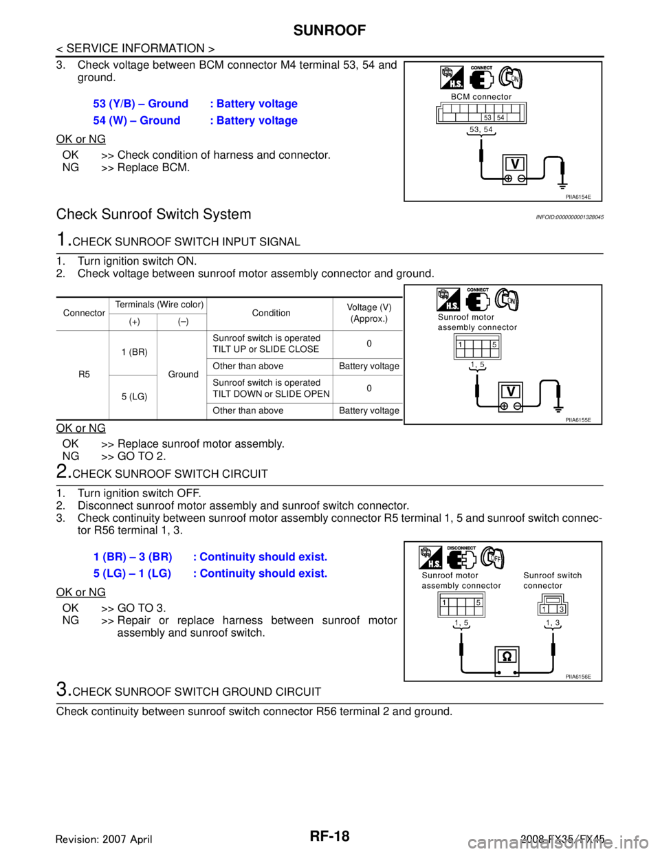
3. Check voltage between BCM connector M4 terminal 53, 54 andground.
OK or NG
OK >> Check condition of harness and connector.
NG >> Replace BCM.
Check Sunroof Switch SystemINFOID:0000000001328045
1.CHECK SUNROOF SWITCH INPUT SIGNAL
1. Turn ignition switch ON.
2. Check voltage between sunroof motor assembly connector and ground.
OK or NG
OK >> Replace sunroof motor assembly.
NG >> GO TO 2.
2.CHECK SUNROOF SWITCH CIRCUIT
1. Turn ignition switch OFF.
2. Disconnect sunroof motor assembly and sunroof switch connector.
3. Check continuity between sunroof motor assembly c onnector R5 terminal 1, 5 and sunroof switch connec-
tor R56 terminal 1, 3.
OK or NG
OK >> GO TO 3.
NG >> Repair or replace harness between sunroof motor assembly and sunroof switch.
3.CHECK SUNROOF SWITCH GROUND CIRCUIT
Check continuity between sunroof switch connector R56 terminal 2 and ground. 53 (Y/B) – Ground : Battery voltage
54 (W) – Ground : Battery voltage
PIIA6154E
Connector
Terminals (Wire color)
ConditionVoltage (V)
(Approx.)
(+) (–)
R5 1 (BR)
GroundSunroof switch is operated
TILT UP or SLIDE CLOSE
0
Other than above Battery voltage
5 (LG) Sunroof switch is operated
TILT DOWN or SLIDE OPEN
0
Other than above Battery voltage
PIIA6155E
1 (BR) – 3 (BR) : Continuity should exist.
5 (LG) – 1 (LG) : Continuity should exist.
PIIA6156E
3AA93ABC3ACD3AC03ACA3AC03AC63AC53A913A773A893A873A873A8E3A773A983AC73AC93AC03AC3
3A893A873A873A8F3A773A9D3AAF3A8A3A8C3A863A9D3AAF3A8B3A8C
Page 3534 of 3924
SUNROOFRF-19
< SERVICE INFORMATION >
C
DE
F
G H
J
K L
M A
B
RF
N
O P
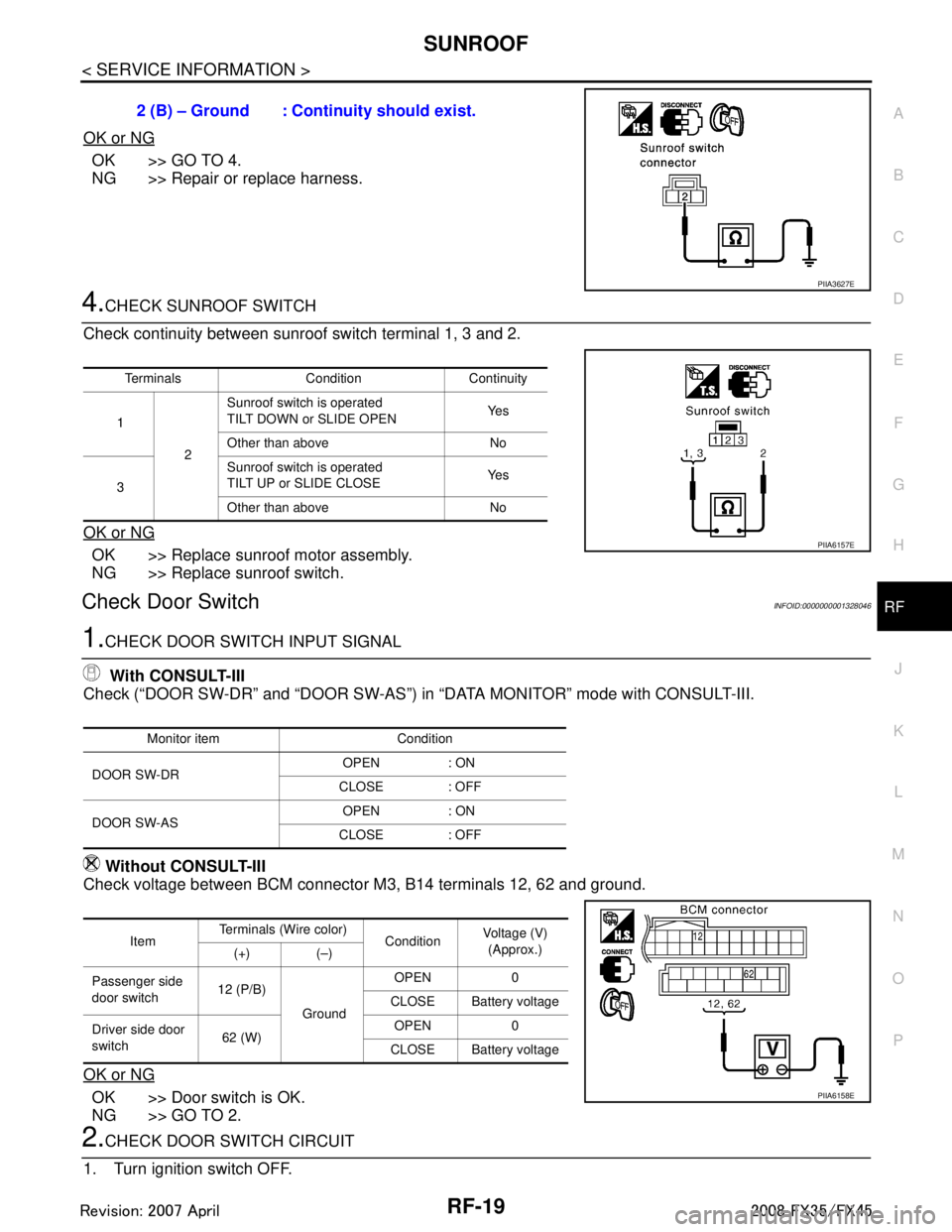
OK or NG
OK >> GO TO 4.
NG >> Repair or replace harness.
4.CHECK SUNROOF SWITCH
Check continuity between sunroof switch terminal 1, 3 and 2.
OK or NG
OK >> Replace sunroof motor assembly.
NG >> Replace sunroof switch.
Check Door SwitchINFOID:0000000001328046
1.CHECK DOOR SWITCH INPUT SIGNAL With CONSULT-III
Check (“DOOR SW-DR” and “DOOR SW-AS”) in “DATA MONITOR” mode with CONSULT-III.
Without CONSULT-III
Check voltage between BCM connector M3, B14 terminals 12, 62 and ground.
OK or NG
OK >> Door switch is OK.
NG >> GO TO 2.
2.CHECK DOOR SWITCH CIRCUIT
1. Turn ignition switch OFF. 2 (B) – Ground : Continuity should exist.
PIIA3627E
Terminals Condition Continuity
1 2Sunroof switch is operated
TILT DOWN or SLIDE OPEN
Ye s
Other than above No
3 Sunroof switch is operated
TILT UP or SLIDE CLOSE
Ye s
Other than above No
PIIA6157E
Monitor item Condition
DOOR SW-DR OPEN : ON
CLOSE : OFF
DOOR SW-AS OPEN : ON
CLOSE : OFF
Item Terminals (Wire color)
ConditionVoltage (V)
(Approx.)
(+) (–)
Passenger side
door switch 12 (P/B)
Ground OPEN 0
CLOSE Battery voltage
Driver side door
switch 62 (W) OPEN 0
CLOSE Battery voltage
PIIA6158E
3AA93ABC3ACD3AC03ACA3AC03AC63AC53A913A773A893A873A873A8E3A773A983AC73AC93AC03AC3
3A893A873A873A8F3A773A9D3AAF3A8A3A8C3A863A9D3AAF3A8B3A8C
Page 3601 of 3924
SB-2
< SERVICE INFORMATION >
PRECAUTIONS
SERVICE INFORMATION
PRECAUTIONS
Precaution for Supplemental Restraint System (SRS) "AIR BAG" and "SEAT BELT
PRE-TENSIONER"
INFOID:0000000001612908
The Supplemental Restraint System such as “A IR BAG” and “SEAT BELT PRE-TENSIONER”, used along
with a front seat belt, helps to reduce the risk or severi ty of injury to the driver and front passenger for certain
types of collision. This system includes seat belt switch inputs and dual stage front air bag modules. The SRS
system uses the seat belt switches to determine the front air bag deployment, and may only deploy one front
air bag, depending on the severity of a collision and w hether the front occupants are belted or unbelted.
Information necessary to service the system safely is included in the “SUPPLEMENTAL RESTRAINT SYS-
TEM” and “SEAT BELTS” of this Service Manual.
WARNING:
• To avoid rendering the SRS inopera tive, which could increase the risk of personal injury or death in
the event of a collision which would result in air bag inflation, all maintenance must be performed by
an authorized NISS AN/INFINITI dealer.
Improper maintenance, including in correct removal and installation of the SRS, can lead to personal
injury caused by unintent ional activation of the system. For re moval of Spiral Cable and Air Bag
Module, see the “SUPPLEMEN TAL RESTRAINT SYSTEM”.
Do not use electrical test equipmen t on any circuit related to the SRS unless instructed to in this
Service Manual. SRS wiring harnesses can be identi fied by yellow and/or orange harnesses or har-
ness connectors.
Precaution for Seat Belt ServiceINFOID:0000000001327733
CAUTION:
Before removing the front seat belt pre-tensione r assembly, turn the ignition switch off, disconnect
the both battery cables and wait at least 3 minutes.
Do not use electrical test equipment for front seat belt pre-tensioner connector.
After replacing or reinstalling front seat belt pr e-tensioner assembly, or reconnecting front seat belt
pre-tensioner connector, check the system function. Refer to SRS-23, "
SRS Operation Check".
Do not use disassemble buckle or seat belt assembly.
Replace anchor bolts if they are deformed or worn out.
Never oil tongue and buckle.
If any component of seat belt assembly is questionable, do not re pair. Replace the whole seat belt
assembly.
If webbing is cut, frayed, or damaged, replace seat belt assembly.
When replacing seat belt assembly, use a genuine NISSAN seat belt assembly.
Disposal, recycling, and transportation of air ba g modules and seat belt pre-tensioners should be
performed in compliance with applicable fede ral, state and local laws and regulations.
AFTER A COLLISION
WARNING:
Inspect all seat belt assemblies including retractors and attaching hardware after any collision.
NISSAN recommends that all seat belt assemblies in use during a collision be replaced unless the col-
lision was minor and the belts show no damage and continue to operate properly. Failure to do so
could result in serious personal injury in an acci dent. Seat belt assemblies not in use during a colli-
sion should also be replaced if either damage or im proper operation is noted. Seat belt pre-tensioner
should be replaced even if the seat belts are not in use during a frontal collision in which the air bags
are deployed.
Replace any seat belt assembly (including anchor bolts) if:
The seat belt was in use at the time of a collision (except for minor collisions and the belts, retractors and
buckles show no damage and continue to operate properly).
The seat belt was damaged in an accident. (i.e. torn webbing, bent retractor or guide).
The seat belt attaching point was damaged in an acci dent. Inspect the seat belt attaching area for damage
or distortion and repair as necessary before installing a new seat belt assembly.
Anchor bolts are deformed or worn out.
The front seat belt pre-tensioner should be replaced even if the seat belts are not in use during the collision
in which the air bags are deployed.
3AA93ABC3ACD3AC03ACA3AC03AC63AC53A913A773A893A873A873A8E3A773A983AC73AC93AC03AC3
3A893A873A873A8F3A773A9D3AAF3A8A3A8C3A863A9D3AAF3A8B3A8C
Page 3602 of 3924
SEAT BELTSSB-3
< SERVICE INFORMATION >
C
DE
F
G
I
J
K L
M A
B
SB
N
O P
SEAT BELTS
System DescriptionINFOID:0000000001327734
SEAT BELT WARNING CHIME
With ignition switch turned ON and seat belt unfastened (seat belt switch ON), warning chime will sound for
approximately 6 seconds.
If warning chime does not sound, refer to DI-61, "
Symptom Chart" in DI section.
SEAT BELT WARNING LAMP
Fasten driver's seat belt.
The seat belt warning lamp should go out.
If the seat belt warning lamp does not go out, refer to DI-36, "
Wiring Diagram - WARN -".
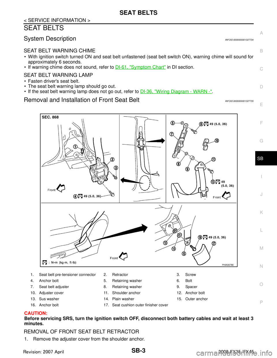
Removal and Installation of Front Seat BeltINFOID:0000000001327735
CAUTION:
Before servicing SRS, turn the igni tion switch OFF, disconnect both ba ttery cables and wait at least 3
minutes.
REMOVAL OF FRONT SEAT BELT RETRACTOR
1. Remove the adjuster cover from the shoulder anchor.
1. Seat belt pre-tensioner connector 2. Retractor 3. Screw
4. Anchor bolt 5. Retaining washer 6. Bolt
7. Seat belt adjuster 8. Retaining washer 9. Spacer
10. Adjuster cover 11. Shoulder anchor 12. Anchor bolt
13. Sus washer 14. Plain washer 15. Outer anchor
16. Anchor bolt 17. Seat cushion outer finisher cover
PHIA0678E
3AA93ABC3ACD3AC03ACA3AC03AC63AC53A913A773A893A873A873A8E3A773A983AC73AC93AC03AC3
3A893A873A873A8F3A773A9D3AAF3A8A3A8C3A863A9D3AAF3A8B3A8C
Page 3605 of 3924
SB-6
< SERVICE INFORMATION >
SEAT BELTS
6. Remove the outer side retractor and center seat retractor mounting anchor bolts.
7. Remove the seat belt assembly.
INSTALLATION OF REAR SEAT BELT RETRACTOR
Install in the reverse order of removal.
Seat Belt InspectionINFOID:0000000001327737
AFTER A COLLISION
WARNING:
Inspect all seat belt assemblies in cluding retractors and attaching hardware after any collision.
NISSAN recommends that all seat belt assemblies in use during a collision be replaced unless the col-
lision was minor and the belts show no damage and continue to operate properly. Failure to do so
could result in serious personal injury in an acci dent. Seat belt assemblies not in use during a colli-
sion should also be replaced if ei ther damage or improper operation is noted. Seat belt pre-tensioners
should be replaced even if the seat belts are not in use during a frontal collision in which the air bags
are deployed.
Replace any seat belt assembly (including anchor bolts) if:
The seat belt was in use at the time of a collision (except for minor collisions and the belts, retractors and
buckles show no damage and continue to operate properly).
The seat belt was damaged in an accident. (i.e. torn webbing, bent retractor or guide).
The seat belt attaching point was damaged in an acci dent. Inspect the seat belt attaching area for damage
or distortion and repair as necessary before installing a new seat belt assembly.
Anchor bolts are deformed or worn out.
The front seat belt pre-tensioner should be replaced even if the seat belts are not in use during the collision
in which the air bags are deployed.
PRELIMINARY CHECK
1. Check the seat belt warning lamp/chime for proper operation as follows:
a. Turn ignition switch ON. The seat belt warning lamp should illuminate. Also, the seat belt warning chime should sound for about six seconds.
b. Fasten driver's seat belt. The seat belt warni ng lamp should go out and the chime (if sounding) should
stop.
2. If the air bag warning lamp is blinking, perform self-diagnosis using CONSULT-II, and air bag warning lamp. Refer to SRS-23, "
SRS Operation Check".
3. Make sure that the seat belt retractor, seat belt anchor and buckle bolts are securely attached.
4. Check the shoulder seat belt guide and shoulder belt height adjuster for\
front seats. Ensure guide swivels freely and that webbing lays flat and does not bind in guide. Ensure height adjuster operates properly and
holds securely.
5. Check retractor operation:
a. Fully extend the seat belt webbing and c heck for twists, tears or other damage.
b. Allow the seat belt to retract. Ensure that webbing returns smoothly and completely into the retractor. If
the seat belt does not return smoothly, wipe the insi de of the loops with a clean paper cloth, because dirt
built up in the loops of the upper anchors can cause the seat belts to retract slowly.
c. Fasten the seat belt. Check the seat belt returns sm oothly and completely to the retractor. If the webbing
does not return smoothly, the cause may be an accumulation of dust or dirt. Use the “SEAT BELT TAPE
SET” and perform the following steps.
Inspect the front seat belt through-anchor:
1. Pull the seat belt out to a length of 500 mm (19.69 in) or more.
2. Use a clip or other device to the fix the seat belt at the center pillar webbing opening.
3. Pass a thin wire through the through-anchor webbing opening. Hold both ends of the wire and pull taut while moving it up and down several times along the webbing opening surface to remove dirt.
4. Any dirt that cannot be removed with the wir e can be removed by cleaning the opening with a clean
cloth.
5. Apply tape at the point where the webbi ng contacts the through-anchor webbing opening.
NOTE:
Apply the tape so that there is no looseness or wrinkling.
6. Remove the clip fixing the seat belt and ensure that the webbing returns smoothly.
3AA93ABC3ACD3AC03ACA3AC03AC63AC53A913A773A893A873A873A8E3A773A983AC73AC93AC03AC3
3A893A873A873A8F3A773A9D3AAF3A8A3A8C3A863A9D3AAF3A8B3A8C
Page 3617 of 3924

SC-8
< SERVICE INFORMATION >
STARTING SYSTEM
STARTING SYSTEM
System DescriptionINFOID:0000000001328246
Power is supplied at all times
through 40A fusible link (letter F, located in the fuse and fusible link block)
to ignition switch terminal 1,
through 15A fuse (No. 78, located in the IPDM E/R)
to CPU of IPDM E/R,
through 10A fuse (No. 71, located in the IPDM E/R)
to CPU of IPDM E/R.
When the selector lever in the P or N position, power is supplied
from TCM, and through A/T assembly terminal 9
to IPDM E/R terminal 53.
Ground is supplied
to IPDM E/R terminals 38, 50 and 60
from grounds E21, E50 and E51.
With the ignition switch in the START position, and provided that the IPDM E/R receives a starter relay ON sig-
nal from the CAN lines, the IPDM E/ R is energized and power is supplied
from ignition switch terminal 5
to IPDM E/R terminal 4 and
through IPDM E/R terminal 3
to starter motor terminal 1.
The starter motor plunger closes and provides a clos ed circuit between the battery and starter motor. The
starter motor is grounded to the engine block. With power and ground supplied, cranking occurs and the
engine starts.
3AA93ABC3ACD3AC03ACA3AC03AC63AC53A913A773A893A873A873A8E3A773A983AC73AC93AC03AC3
3A893A873A873A8F3A773A9D3AAF3A8A3A8C3A863A9D3AAF3A8B3A8C
Page 3621 of 3924
SC-12
< SERVICE INFORMATION >
STARTING SYSTEM
1. Remove fuel pump fuse.
2. Crank or start the engine (where possible) until the fuel pressure is released.
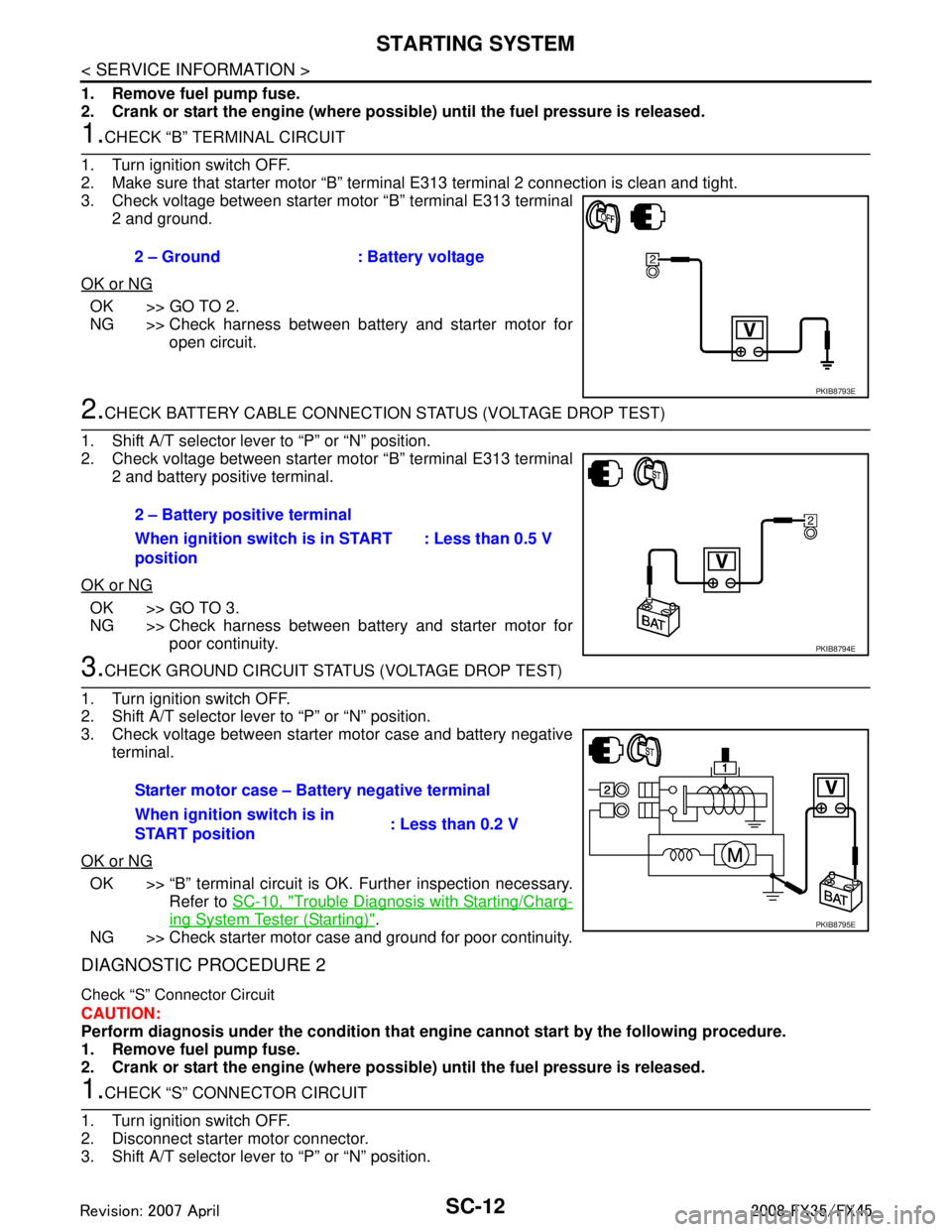
1.CHECK “B” TERMINAL CIRCUIT
1. Turn ignition switch OFF.
2. Make sure that starter motor “B” terminal E313 terminal 2 connection is clean and tight.
3. Check voltage between starter motor “B” terminal E313 terminal 2 and ground.
OK or NG
OK >> GO TO 2.
NG >> Check harness between battery and starter motor for open circuit.
2.CHECK BATTERY CABLE CONNECTION STATUS (VOLTAGE DROP TEST)
1. Shift A/T selector lever to “P” or “N” position.
2. Check voltage between starter motor “B” terminal E313 terminal 2 and battery positive terminal.
OK or NG
OK >> GO TO 3.
NG >> Check harness between battery and starter motor for poor continuity.
3.CHECK GROUND CIRCUIT STATUS (VOLTAGE DROP TEST)
1. Turn ignition switch OFF.
2. Shift A/T selector lever to “P” or “N” position.
3. Check voltage between starter motor case and battery negative terminal.
OK or NG
OK >> “B” terminal circuit is OK. Further inspection necessary. Refer to SC-10, "
Trouble Diagnosis with Starting/Charg-
ing System Tester (Starting)".
NG >> Check starter motor case and ground for poor continuity.
DIAGNOSTIC PROCEDURE 2
Check “S” Connector Circuit
CAUTION:
Perform diagnosis under the condi tion that engine cannot start by the following procedure.
1. Remove fuel pump fuse.
2. Crank or start the engine (where possi ble) until the fuel pressure is released.
1.CHECK “S” CONNECTOR CIRCUIT
1. Turn ignition switch OFF.
2. Disconnect starter motor connector.
3. Shift A/T selector lever to “P” or “N” position. 2 – Ground : Battery voltage
PKIB8793E
2 – Battery positive terminal
When ignition switch is in START
position
: Less than 0.5 V
PKIB8794E
Starter motor case – Battery negative terminal
When ignition switch is in
START position
: Less than 0.2 V
PKIB8795E
3AA93ABC3ACD3AC03ACA3AC03AC63AC53A913A773A893A873A873A8E3A773A983AC73AC93AC03AC3
3A893A873A873A8F3A773A9D3AAF3A8A3A8C3A863A9D3AAF3A8B3A8C