2008 GEELY CK ABS
[x] Cancel search: ABSPage 6 of 392

Section 3 Removal & Installation................................................................................... 262Chapter 8 MK-20 ABS System........................................................................ 2 7 2Section 1 ABS Diagnosis ................................................................................................. 272
Section 2 ABS System Check .......................................................................................... 276
Section 3 Removal and Installation................................................................................. 292Part IV Air Conditioner and Inside & Outside Trim ......................297Chapter 1 A/C System...................................................................................... 2 9 7Section 1 The Structure & Working Principle of Refrigeration System...............................297
Section 2 Heating System ................................................................................................ 299
Section 3 A/C controlling system.................................................................................... 302
Section 4 Service Caution & Notice................................................................................ 304
Section 5 The Refrigeration System Operation Procedure..............................................305
Section 6 Basic System .................................................................................................... 308
Section 7 A/C System Faults Check & Troubleshooting................................................ 313Chapter 2 Inside & outside Trim and Accessory................................................318Section 1 Configuration Index............................................................................................318(I) Outside Trim And Front Accessory.................................................................................318
(II) Outside Trim and Rear Accessory.................................................................................319
(III) Front inside trim..........................................................................................................320
(IV) Rear inside trim ............................................................................................................321Section 2 Inside & Outside Trim and Accessories Removal and Installation.......................322(I) Front Bumper..................................................................................................................322
(II) Engine Hood.................................................................................................................324
(III) Outside Rear View Mirror
(IV) Rear trunk Lid...............................................................................................................327
(V) Rear Bumper...................................................................................................................329
(VI) Seat Removal, Installation and Adjustment...................................................................331
(VII) Seat Belt.....................................................................................................................335
(VIII) Instrument panel and auxiliary console.....................................................................338
(IX) A pillar inside trim and front door sill ............................................................................343
(X) B pillar inside trim........................................................................................................344
(XI) Cpillar inside trim and rear door sill.............................................................................345
(XII) Roof inside trim
(XIII) Carpet and Heat Insulator.............................................................................................347 ...............................................................................................326
...........................................................................................................346
Page 20 of 392

13Section 2 Engine Components Replacement1. Avoid gasoline ejection when work.
2. Drain the coolant to empty.
3. Remove air filter assembly with hose. See (Figure 23)
4. Remove battery
5. Remove fuel delivery pipe sub-assembly
6. Disconnect water hoses, disconnect heater outlet hose
from A/C hose.
7. Loose nut, remove accelerator control cable
8. Remove throttle body assembly
9. Remove power steering pump reservoir assembly
10. Remove front exhaust pipe assembly
11. Remove steering gear boot
12. Seperate steering column assembly. See (Figure 24)
13. Remove front wheel hub nut
14. Disconnect front wheel vehicle speed sensor (with ABS)
15. Detach steering tie rod ball stud pin assembly
16. Detach front lower swing arm sub-assembly
17. Detach front propeller assembly. See (Figure 25)
Detach front propeller from the shaft hub with plastic hammer.
18. Disconnect transmission shift cable or gear shift level assembly
19. Disconnect clutch cylinder assembly or disconnect clutch cable
20. Detach engine assembly and transaxle
(a) Hoisting engine ;
(b) Remove 3 bolts. Detach the right engine mounting bracket. See (Figure 26) ;
(c) Remove 1 bolt. Detach the left engine mounting bracket;
(d) Remove 1 bolt. Detach the rear engine mounting bracket;
(e) Remove engine and transaxle and put them on the pallet;
(f) Jack up the boday.Figure 23
Figure 24
Figure 25 Figure 26
Page 23 of 392

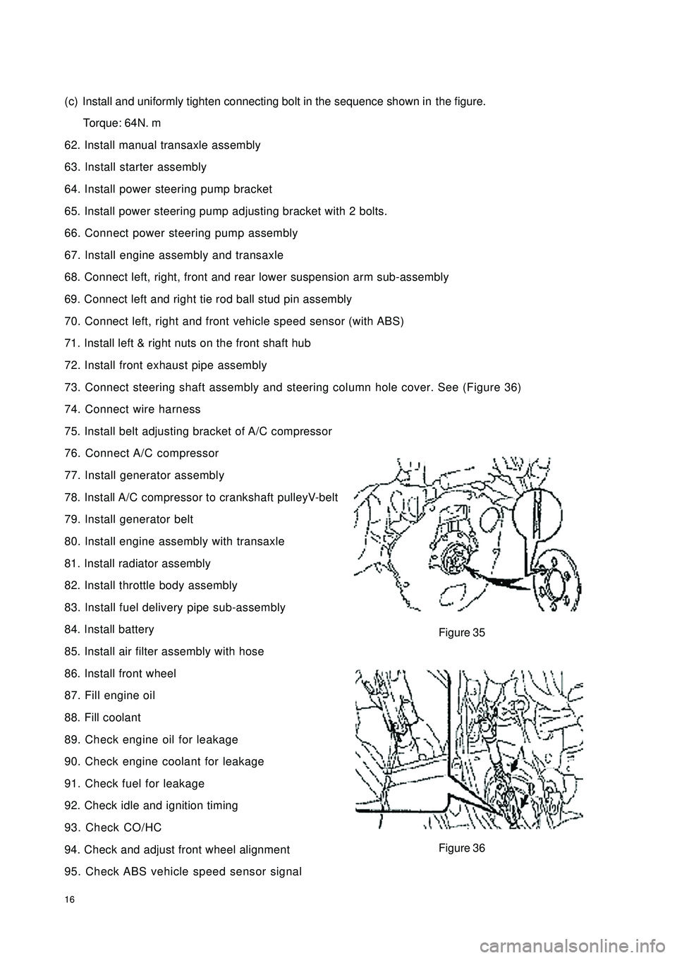
16(c) Install and uniformly tighten connecting bolt in the sequence shown inthe figure.
Torque: 64N. m
62. Install manual transaxle assembly
63. Install starter assembly
64. Install power steering pump bracket
65. Install power steering pump adjusting bracket with 2 bolts.
66. Connect power steering pump assembly
67. Install engine assembly and transaxle
68. Connect left, right, front and rear lower suspension arm sub-assembly
69. Connect left and right tie rod ball stud pin assembly
70. Connect left, right and front vehicle speed sensor (with ABS)
71. Install left & right nuts on the front shaft hub
72. Install front exhaust pipe assembly
73. Connect steering shaft assembly and steering column hole cover. See (Figure 36)
74. Connect wire harness
75. Install belt adjusting bracket of A/C compressor
76. Connect A/C compressor
77. Install generator assembly
78. Install A/C compressor to crankshaft pulleyV-belt
79. Install generator belt
80. Install engine assembly with transaxle
81. Install radiator assembly
82. Install throttle body assembly
83. Install fuel delivery pipe sub-assembly
84. Install battery
85. Install air filter assembly with hose
86. Install front wheel
87. Fill engine oil
88. Fill coolant
89. Check engine oil for leakage
90. Check engine coolant for leakage
91. Check fuel for leakage
92. Check idle and ignition timing
93. Check CO/HC
94. Check and adjust front wheel alignment
95. Check ABS vehicle speed sensor signalFigure 35
Figure 36
Page 67 of 392

60Section 1 Manual Transaxle Replacement1. Open the engine hood
2. Remove the battery
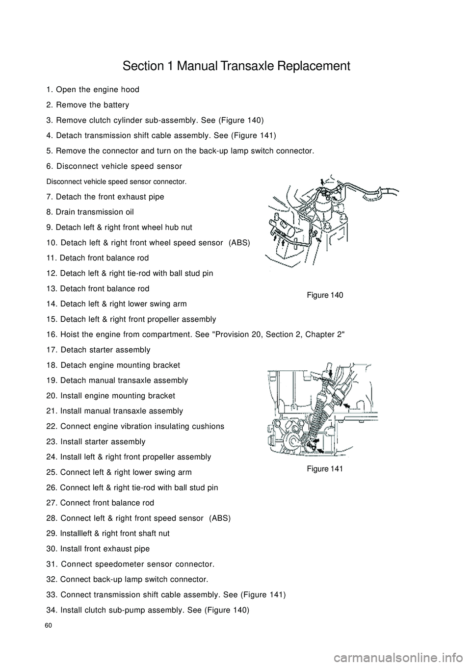
3. Remove clutch cylinder sub-assembly. See (Figure 140)
4. Detach transmission shift cable assembly. See (Figure 141)
5. Remove the connector and turn on the back-up lamp switch connector.
6. Disconnect vehicle speed sensor
Disconnect vehicle speed sensor connector.
7. Detach the front exhaust pipe
8. Drain transmission oil
9. Detach left & right front wheel hub nut
10. Detach left & right front wheel speed sensor (ABS)
11. Detach front balance rod
12. Detach left & right tie-rod with ball stud pin
13. Detach front balance rod
14. Detach left & right lower swing arm
15. Detach left & right front propeller assembly
16. Hoist the engine from compartment. See "Provision 20, Section 2, Chapter 2"
17. Detach starter assembly
18. Detach engine mounting bracket
19. Detach manual transaxle assembly
20. Install engine mounting bracket
21. Install manual transaxle assembly
22. Connect engine vibration insulating cushions
23. Install starter assembly
24. Install left & right front propeller assembly
25. Connect left & right lower swing arm
26. Connect left & right tie-rod with ball stud pin
27. Connect front balance rod
28. Connect left & right front speed sensor (ABS)
29. Installleft & right front shaft nut
30. Install front exhaust pipe
31. Connect speedometer sensor connector.
32. Connect back-up lamp switch connector.
33. Connect transmission shift cable assembly. See (Figure 141)
34. Install clutch sub-pump assembly. See (Figure 140)Figure 140
Figure 141
Page 90 of 392

83ECU microcomputer consists of microprocessor, memory, clock generator, timer, I/O interface and input
level A/D converter that are integrated in a large scale integrated circuit chip, that is SCM (Single Chip
Microcomputer).
1. Input level
The input signals from the sensor are pre-processed by the input level. The input signals are sent to protected
circuit first, sometimes through the signal converter and amplifier, and then sent to microcomputer.
The sensor signal is separated into switch type and analog type. Ignition on/off signal, camshaft position
signal, vehicle speed signal and A/C signal are switch type; Signals such as battery voltage, engine temperature,
intake temperature, airflow, intake manifold absolute pressure, throttle opening, excessive air coefficient,
knock, A/C refrigerant pressure are analog type. Analogy signal can only be processed by the digital micro-
computer after being converted into digital signal by A/D converter. Hence, data collection shall be made
first for analog signal, and the sampling shall be maintained also.
Speed and crankshaft position reference signal from the sensor is processed in a dedicated circuit to restrain
the interference pulse.
2. Microcomputer
The microcomputer of the engine electronic control unit is integrated in a single chip microcomputer, consist-
ing of the following:
(1) Microprocessor, microprocessor is also called as central processing unit (CPU), consisting of the following
three parts:
Arithmetic logic unit.
Register group.
Controller.
(2) System assembly, The data transferred among the internal sections of the single chip microcomputer
(SCM) is performed on the internal bus, while that between the SCM and other components is performed
on the external bus. The external bus is also called system bus. It is separated into data bus, address bus
and control bus.
(3) Memory, the memory is designed to store the binary data. The primary components of the memory are:
Memory.
Data register.
Address register, address decoder.
a. Memory controller
(4) A/D converter
(5) I/O interface.
(6) Clock generator.
(7) Timer
(8) CAPCOM unit.
(9) Watchdog timer.
(10) Interrupt system.
Page 106 of 392

99Service1. Remove the front wheel
2. Remove the ABS sensor signal wire
3. Remove the propeller shaft fixing nut
(1) Remove the cotter pin of the propeller shaft fixing nut
(2) loosen the propeller shaft fixing nut
4. Separate the steering tie rod
(1) Remove the cotter pin and the nut
(2) Separate the tie rod ball stud pin from the knuckle.
5. Detach the swing arm assembly.
(1) Remove the lower swing arm assembly ball stud pin lock bolt and nut on the knuckle
(2) Detach the lower swing arm assembly ball stud pin from the knuckle
6. Remove the constant velocity propeller shaft assembly Appropriately pull the brake outward, use a
rubber hammer or brass bar to tap the propeller shaft to remove itNotice: Actions shall be taken to prevent the propeller from being dropped off, do not damage
the boot and the oil seal7 Inspect the propeller shaft assembly
(1) Check the tripod constant velocity universal joint for looseness
(2) Check the sliding shaft for smooth movement
Page 109 of 392

102(7) Install front wheel, wheel nut torque: 95~115N.m
(8) Make sure that the propeller shafts for 1.3L engine and 1.5L engine are not interchanged
at the time of replacement
(9) Check the ABS sensor signal, check and adjust the front wheel alignment if necessary.
Page 110 of 392

103Chapter 5 Front Suspension SystemSection 1 Front Suspension SystemDescription on front suspension structure
This model uses strut swing arm independent suspension with stabilizer bar.
The shock absorber upper end is flexibly connected to the body through the shock absorber mounting seat,
the lower end is rigidly connected to the steering knuckle. The coil spring encloses the shock absorber (coil
spring geometrical axial line does not coincide with that of the shock absorber piston rod), and is supported
between the upper and lower spring seats.
Both ends of the stabilizer bar are connected to the shock absorber through the strut bar ball pin and the
intermediate part is supported on the lower front body by the rubber bushing and support frame.
The front cushion sleeves the shock absorber piston rod head to restrict the wheel jump limit position and
plays the role of buffer.
The thrust ball bearing, installed between the spring upper seat and the shock absorber mount, is used for the
relative rotation upon steering of the shock absorber rigidly connected to the steering knuckle to the shock
absorber mount flexibly connected to the body.
"L" type lower swing arm is secured to the lower engine compartment with the press plate through elastic
rubber bushing and hinge, and its outer end is connected to the steering knuckle through the ball stud pin
which is attached to the lower swing arm by 3 high intension bolts. The ball stud pin can be removed and
replaced when it is worn.
The ball seat material is saturated polyester containing oil, featured in comparatively high intensity and
wearability and good self-lubrication performance. Proper amount of grease has been added during the
assembly and there is no need for additional filling during the normal operation.
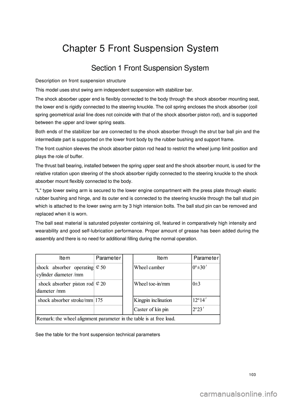
See the table for the front suspension technical parametersItem Parameter Item Parameter
shoc k a bsorbe r ope ra ting
cylinder diameter /mm¢
50 Wheel camber 0°±30′
shoc k a bsorbe r piston rod
diameter /mm¢
20 Wheel toe-in/mm 0±3
shoc k a bsorbe r stroke /mm 175 Kingpin inc lina tion 12°14′
Ca ste r of kin pin 2°23′
Remark: the wheel alignment parameter in the table is at free load.