Page 142 of 392

135Replacement1. Drain the power steering system fluid
2. Remove the power steering high and low pressure pipe
3. Loosen the union screw of the high and low pressure pipe on the steering gear assembly, loosen the pipe
clip.
4. Loosen the drive belt
5. Remove the power steering pump with bracket assembly from the engine
Remove the 4 attaching bolts between the steering pump belt bracket and the engine6.Install the power steering pump bracket assemblySecure the power steering pump bracket assembly to the engine,
The torque of the M10 bolt is 45~79N.m, the torque of the M8 bolt is 16~26N.m7. Install the drive belt, make sure the installation position is correct
8. Install the power steering high and low pressure pipe(1)Connect the union thread of the high and low pressure pipe to the steering gear,
torque: 19~33N.m
(2) Use the retaining clip to secure the low pressure pipe to the cowl baffle panel of the body
(3)Connect the union thread of the high pressure pipe to the power steering pump,
torque: 19~33N.m
(4) Connect the union thread of the low pressure pipe to the reservoir, torque: 19~33N.m
9. Bleed the power steering pipeline system, check the pipeline system for leakage
10. Check the oil reservoir inner fluid level
Page 149 of 392

142(3) The 3 bolts connecting the brake pedal support bracket and cowl panel cross member
Torque : 16-20N.m
(4) The 4 bolts connecting the brake pedal support bracket and the vacuum booster with
brake master cylinder assembly
Torque: 16-20N.mCheck the brake pedal1. Check and adjust brake pedal height
(a) Brake pedal height from the ground: normal height is 176~181 mm.
(b) Adjust brake pedal height
(1) Loosen the brake lamp switch lock nut
(2) Adjust the brake lamp switch to the right position
(3) Check the brake lamp switch
Make sure the brake lamp is light by depressing the brake pedal for5~15mm
(4) Tighten the brake lamp switch lock nut
2. Check pedal freestroke
(1) Shut off the engine and depress the brake pedal several times until there is no more vacuum left in
the booster.
(2) Depress the pedal until the resistance begins to be felt
Pedal freestroke should be: 10~30mmWorn Or DamagedWorn Or DamagedWorn Or
DamagedWorn Or
DamagedWorn Or DamagedWorn Or DamagedDistorted Or DamagedDistorted Or DamagedBent Or DistortedFreestroke
Page 150 of 392

143Section 4 Vacuum Booster with Brake Master Cylinder AssemblyNotice: The vacuum booster with brake master cylinder assembly must be repaired by
manufacturer. Replace it if it is faulty.On-vehicle inspection1. Check vacuum booster
(a) Air tightness check
(1) start the engine, run 1 or 2 minutes then shut off. Depress the brake pedal several times slightly.
Hint: if the pedal rises gradually after depressing the pedal, the booster is airtight.
(2) Depress the brake pedal while the engine is running, and stop the engine with the pedal depressed.
Hint: if there is no change in the pedal reserve stroke after holding the pedal for 30 seconds,
the booster is air--tight.
(b) Operating check
Depress the brake pedal and start the engine. If the pedal goes down slightly, operation is normal.
2. Check the vacuum check valve
(1) Remove the connecting pipe with the check valve
(2) Check the direction from the booster to the engine. Check valve for ventilation. It should not
ventilate in the reverse order.
(3) Replace it if it is faulty.
Notice: Pay attention to the matchmark on the connecting hose when connecting
the hose with vacuum check valve. Do not install it in reverse order.Replacement1. Remove the brake pipe on the brake master cylinder (master cylinder)
2. Refer to Brake Pedal Replacement for other operation
Notice:
(1) The torque of the union thread on the brake master cylinder (master cylinder )
and brake pipe: 12-16 N.m
(2) Bleed all the air in the brake system after installationGoodPoorThird
Second
First
Page 164 of 392

157Part III Electrical EquipmentChapter 1 SurveyThis part refers to the electrical repair of the Free Cruiser, and analyzes the faults from every system. Then
some practicable diagnosis procedure and repair ways are given.I. HAND-HELD TESTER1. Before the tester is used, a through reading of the Tester Operation Manual is commended.
2. Connect the tester to the diagnosis interface with a wire. Turn the ignition switch ON. At this time, if the
tester and ECU control system cannot communicate, the vehicle or the tester may have faults.
(1) Connect the tester lead wire to another vehicle. If the communication is normal, inspect the vehicle
diagnosis Busline or power supply circuit.
(2) If it still cannot communicate when connecting to the other vehicles, it may have faults on tester itself.
Consult the self-inspecting procedure described on the Tester Operation ManualII. HOW TO PROCEED WITH TROUBLESHOOTINGThe basic operation procedure for troubleshooting is as follows.
1. Customer fault analysis
(a) Ask the customer for the conditions and environment when faults happen.
2. Confirm the fault symptoms, and check the DTCs and storage data.
(a) Check the battery positive voltage (Voltage: 10 - 14V when the engine is stopped.)
(b) Inspect the harness, connector and fuse for open and short, etc. by their appearance.
(c) Warm up the engine temperature to the normal operation temperature.
(d) Confirm the fault symptoms and check the DTCs.
(e) Confirm the test procedure for the parts or systems that need checking.
3. Circuit or part inspection
4. Repair
5. Test for checking
(a) After the repair is completed, verify if the fault has been removed.
(If the fault has not appeared yet, a verifying test should be done under the same conditions and environment
when the fault first occurred.)
Page 166 of 392

1594Make a simulation test in a way of symptom simulation
5Inspect DTC
6Confirm symptomV. SYMPTOM SIMULATIONNOTES:
The most difficult conditions to handle in the fault troubleshooting are that the fault symptom dose not appear.
Under the circumstances, make sure first to make a comprehensive analysis to the fault described by the
customer, then to simulate an environment that is similar or the same with the conditions when the fault of the
customer's vehicle occurred. No matter how rich the experience of the technician is and how skillful he is, if
he make a fault troubleshooting analysis without confirm the fault symptom, it is inevitable for him to neglect
some important factors and incorrectly guess, which may cause barriers to repair. For example, if a fault
occurs only when the engine is cool or if a fault occurs only caused by a vibration from pavement and so on,
when the engine is checked in the hot or static state, it is no way to confirm. Because of vibration, high-
temperature or seeping water (Vapor) often causes some faults that are difficult to reappear. So, here are
some effective symptom simulation tests.
KEY POINTS OF SYMPTOM SIMULATION TEST:
In the symptom simulation test, no doubt it is important to confirm the fault symptom, but the fault position or
fault components must be also found out. So, before the test and the pre-inspection of connection, narrow the
range of the circuit where faults may occur according to the fault symptom. Then make a symptom simula-
tion test to see if the circuit measured is normal; the fault symptom is also verified at the same time.
1. Way of Vibration: When vibration may be the major cause of the fault.
For example:
(a) Use your hand to gently vibrate the sensor that is considered the cause of the fault, in order to check if it
is ineffective.
(b) Softly rock the connector and harness in horizontal and vertical direction.
Notes: Hard rock may cause the relay circuit open.
2. Way of Spraying Water: When rainy weather or wet environment may be the major cause of the fault.
(a) Spray water on the vehicle to check if the fault occurs.
NOTES:
�yBe sure not to directly spray water into the engine compartment. Spray the water on the face of the
radiator to change the temperature and humidity indirectly.
�yBe sure not to spray water onto electronic devices and controllers.
Page 173 of 392
166II. CHARGING SYSTEM INSPECTION1. CHECK BATTERY WORKING VOLTAGE
(a) After having driven the vehicle and in the case that 20 minutes have not passed after having stopped the
engine, turn the ignition switch ON and turn on the electrical system (headlight, blower motor) for 60
seconds to remove the surface charge.
(b) Turn the ignition switch OFF and
turn off the electrical systems. Then
measure the battery voltage
between the negative and positive
terminals of the battery.
Standard voltage: 12.5-12.9V at
20°C
HINT:
If the voltage is less than specification, charge the battery.
2. CHECK BATTERY TERMINALS, FUSE BOX AND FUSE
(a) Check that the battery terminals are not loose or corroded.
(b) Check if fuse box and fuse for continuity.
Page 174 of 392
1673. INSPECT DRIVE BELT
(a) Check the belt for excessive wear, frayed cords etc.
HINT:
�yIf any defect has been found, replace the drive belt.
�yCracks on the rib side of a belt are considered acceptable. If
the belt has chunks missing from the ribs, it should be
replaced.
(b) Check that the belt fits properly in the ribbed grooves.
HINT:
Check with your hand to confirm that the belt has not slipped
out of the groove on the pulley.
4. CHECK ALTERNATOR WIRING
�yCheck that the wiring is in good condition.
5. LISTEN FOR ABNORMAL NOISES FROM ALTERNATOR
�y Check that there is no abnormal noise from the alternator while the engine is running.
6. INSPECT CHARGE WARNING LIGHT CIRCUIT
(1) Turn the ignition ON. Check that the charge warning light comes on.
(2) Start the engine. Check that the light goes off.
HINT:
If the light does not operate as specified, troubleshoot the charge warning light circuit.
Page 175 of 392

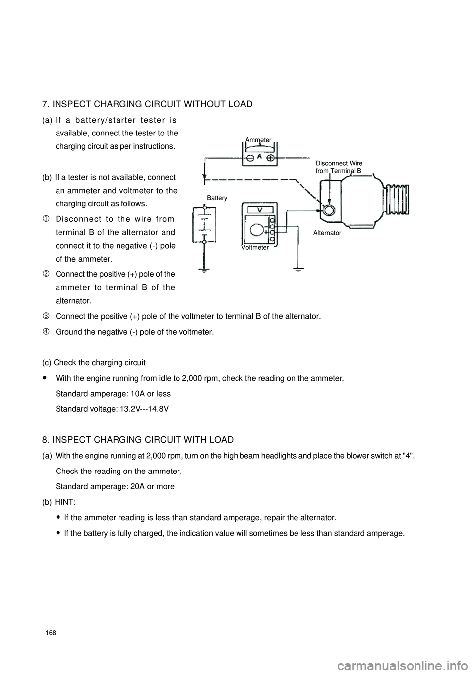
1687. INSPECT CHARGING CIRCUIT WITHOUT LOAD
(a) If a battery/starter tester is
available, connect the tester to the
charging circuit as per instructions.
(b) If a tester is not available, connect
an ammeter and voltmeter to the
charging circuit as follows.
1Disconnect to the wire from
terminal B of the alternator and
connect it to the negative (-) pole
of the ammeter.
2Connect the positive (+) pole of the
ammeter to terminal B of the
alternator.
3Connect the positive (+) pole of the voltmeter to terminal B of the alternator.
4Ground the negative (-) pole of the voltmeter.
(c) Check the charging circuit
�yWith the engine running from idle to 2,000 rpm, check the reading on the ammeter.
Standard amperage: 10A or less
Standard voltage: 13.2V---14.8V
8. INSPECT CHARGING CIRCUIT WITH LOAD
(a) With the engine running at 2,000 rpm, turn on the high beam headlights and place the blower switch at "4".
Check the reading on the ammeter.
Standard amperage: 20A or more
(b) HINT:
�yIf the ammeter reading is less than standard amperage, repair the alternator.
�yIf the battery is fully charged, the indication value will sometimes be less than standard amperage.Ammeter
Disconnect Wire
from Terminal B
Battery
VoltmeterAlternator