Page 91 of 392

843. Output Level
ECU output level is designed to send control signal to the actuators of the electronic control system based on
the orders of the microprocessor in the micro-controller. The microprocessor control the output level by
controlling the occurrence position of the pulse, its length and duty ratio.
(1) Injection output level
The microprocessor controls the pulse length of the injection output level by making sure whether to
trigger to circuit or not in the injection output level.
(2) Ignition input level
The ignition output level is designed to amplify the ignition signal from the microprocessor into the primary
current of the ignition coil.
(3) Electric fuel pump output level
ECU microcontroller control the pump relay through electric fuel pump output level, and then control the
on and off of the electric fuel pump based on the current operating conditions.
(4) Other output levels
Control the output levels of the idle control valve, carbon canister solenoid valve, malfunction indicator
lamp. MR479Q, MR479QA, MR481QA engine idle control are closed loop control system, their injection
and ignition control are also closed loop control system.
Page 92 of 392

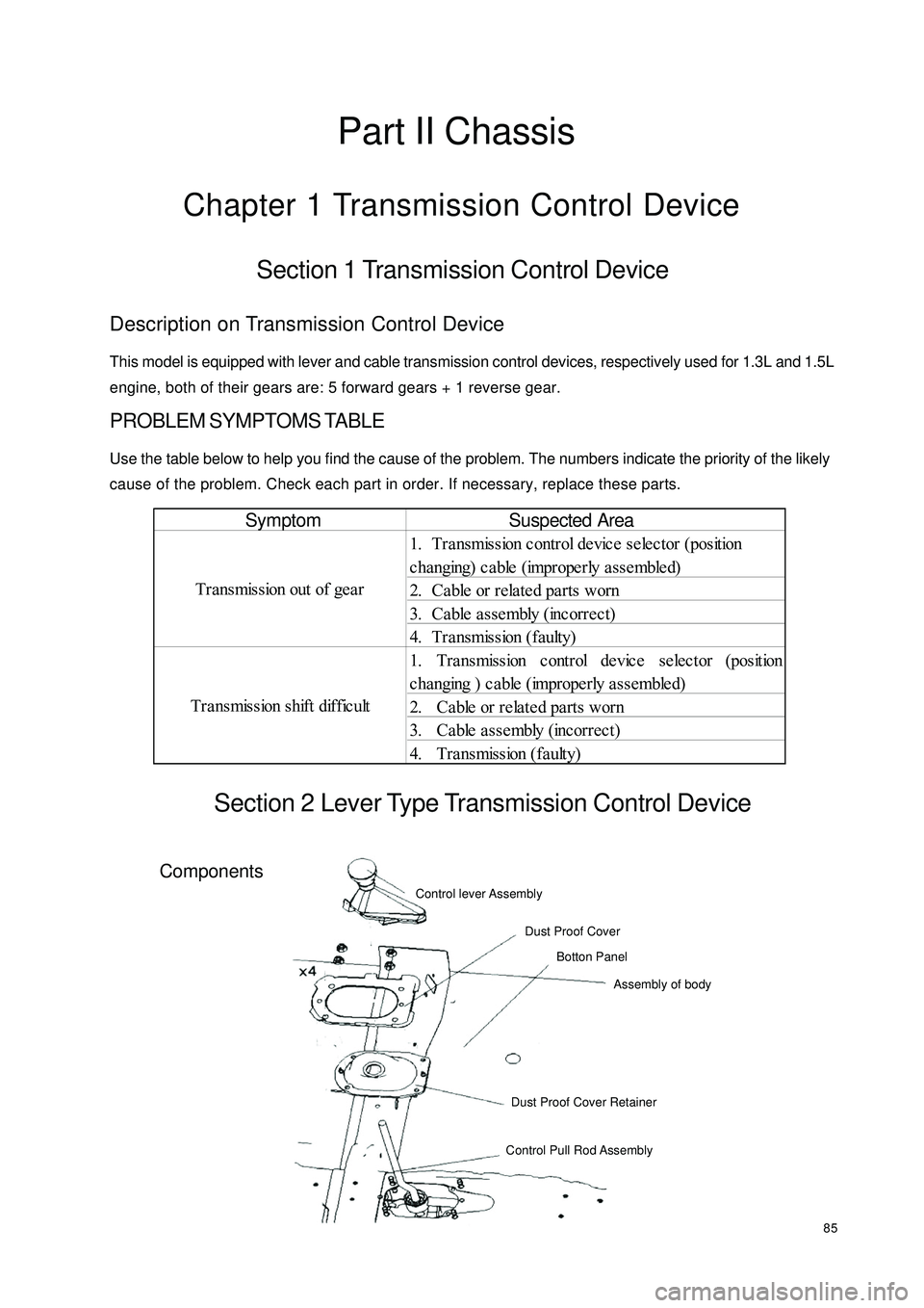
85Part II ChassisChapter 1 Transmission Control DeviceSection 1 Transmission Control DeviceDescription on Transmission Control DeviceThis model is equipped with lever and cable transmission control devices, respectively used for 1.3L and 1.5L
engine, both of their gears are: 5 forward gears + 1 reverse gear.PROBLEM SYMPTOMS TABLEUse the table below to help you find the cause of the problem. The numbers indicate the priority of the likely
cause of the problem. Check each part in order. If necessary, replace these parts.Section 2 Lever Type Transmission Control DeviceComponentsSymptom
1. Tra nsmission c ontrol de vic e se le ctor (position
changing) cable (improperly assembled)
2. Ca ble or rela te d pa rts worn
3. Ca ble a sse mbly (incorrec t)
4. T r a ns mis s ion ( f a ult y)
1. Transmission control device selector (position
changing ) cable (improperly assembled)
2. Ca ble or rela te d pa rts worn
3. Ca ble a sse mbly (incorrec t)
4. Transmission (faulty) Transmission out of gea r
Transmission shift difficultControl lever Assembly
Dust Proof Cover
Botton Panel
Assembly of body
Dust Proof Cover Retainer
Control Pull Rod AssemblySuspected Area
Page 97 of 392
90Chapter 2 Accelerator PedalSection 1 Accelerator PedalComponents
Replacement1. Remove the accelerator cable
Loosen the set nut attaching the accelerator cable to the accelerator
cable bracket on the engine, remove the accelerator cable from
the throttle valve rocker arm
2. Remove accelerator pedal
(1) Remove two set nut between the accelerator pedal
and vehicle body
(2) Separate the accelerator cable
3. Detach the accelerator cable
4.Install the accelerator cable and accelerator pedal assembly in the reverse order of the
Notice:
(1) Accelerator pedal assembly fixing bolt torque: 20~25N.m
(2) Properly adjust the position of the accelerator cable set screw to ensure the adequate
tension of the accelerator cable
(3) Check whether the accelerator control is flexible and reliableCowl BaffleHole Plug
Accelerator
Pedal Assembly Accelerator CableAdjusting NutConnect
The Engineabove procedure.
Page 98 of 392
91Chapter 3 Clutch Control SystemSection 1 Clutch Control SystemClutch operating system descriptionThis model is equipped with hydraulic and cable clutch control system, respectively used for 1.3L engine
1.5L engine.PROBLEM SYMPTOMS TABLEUse the table below to help you find the cause of the problem. The numbers indicate the priority of the likely
cause of the problem. Check each part in order. If necessary, replace these parts.Section 2 Clutch Cable Control MechanismComponentsSympto m Sus pe cte d Are a
1. Clutc h pe da l position (Too low)
2. Control mec ha nism (Stagna tion)
3. Clutc h pe da l fre e stroke (too la rge)
C lut c h doe s not r e le a s e 1. H ydr a ulic pipe line ( A ir in line )
1. Control system (Incorrect assembly & adjustment)
2. Clutc h asse mbly (Fa ulty) Clutch noisyC lut c h s lipsConnect The
Clutch Fork Clutch Cable
Assmbly
Adjusting NutCowl Baffle
Clutch and Brake
Pedal Assembly
Page 109 of 392
102(7) Install front wheel, wheel nut torque: 95~115N.m
(8) Make sure that the propeller shafts for 1.3L engine and 1.5L engine are not interchanged
at the time of replacement
(9) Check the ABS sensor signal, check and adjust the front wheel alignment if necessary.
Page 110 of 392

103Chapter 5 Front Suspension SystemSection 1 Front Suspension SystemDescription on front suspension structure
This model uses strut swing arm independent suspension with stabilizer bar.
The shock absorber upper end is flexibly connected to the body through the shock absorber mounting seat,
the lower end is rigidly connected to the steering knuckle. The coil spring encloses the shock absorber (coil
spring geometrical axial line does not coincide with that of the shock absorber piston rod), and is supported
between the upper and lower spring seats.
Both ends of the stabilizer bar are connected to the shock absorber through the strut bar ball pin and the
intermediate part is supported on the lower front body by the rubber bushing and support frame.
The front cushion sleeves the shock absorber piston rod head to restrict the wheel jump limit position and
plays the role of buffer.
The thrust ball bearing, installed between the spring upper seat and the shock absorber mount, is used for the
relative rotation upon steering of the shock absorber rigidly connected to the steering knuckle to the shock
absorber mount flexibly connected to the body.
"L" type lower swing arm is secured to the lower engine compartment with the press plate through elastic
rubber bushing and hinge, and its outer end is connected to the steering knuckle through the ball stud pin
which is attached to the lower swing arm by 3 high intension bolts. The ball stud pin can be removed and
replaced when it is worn.
The ball seat material is saturated polyester containing oil, featured in comparatively high intensity and
wearability and good self-lubrication performance. Proper amount of grease has been added during the
assembly and there is no need for additional filling during the normal operation.
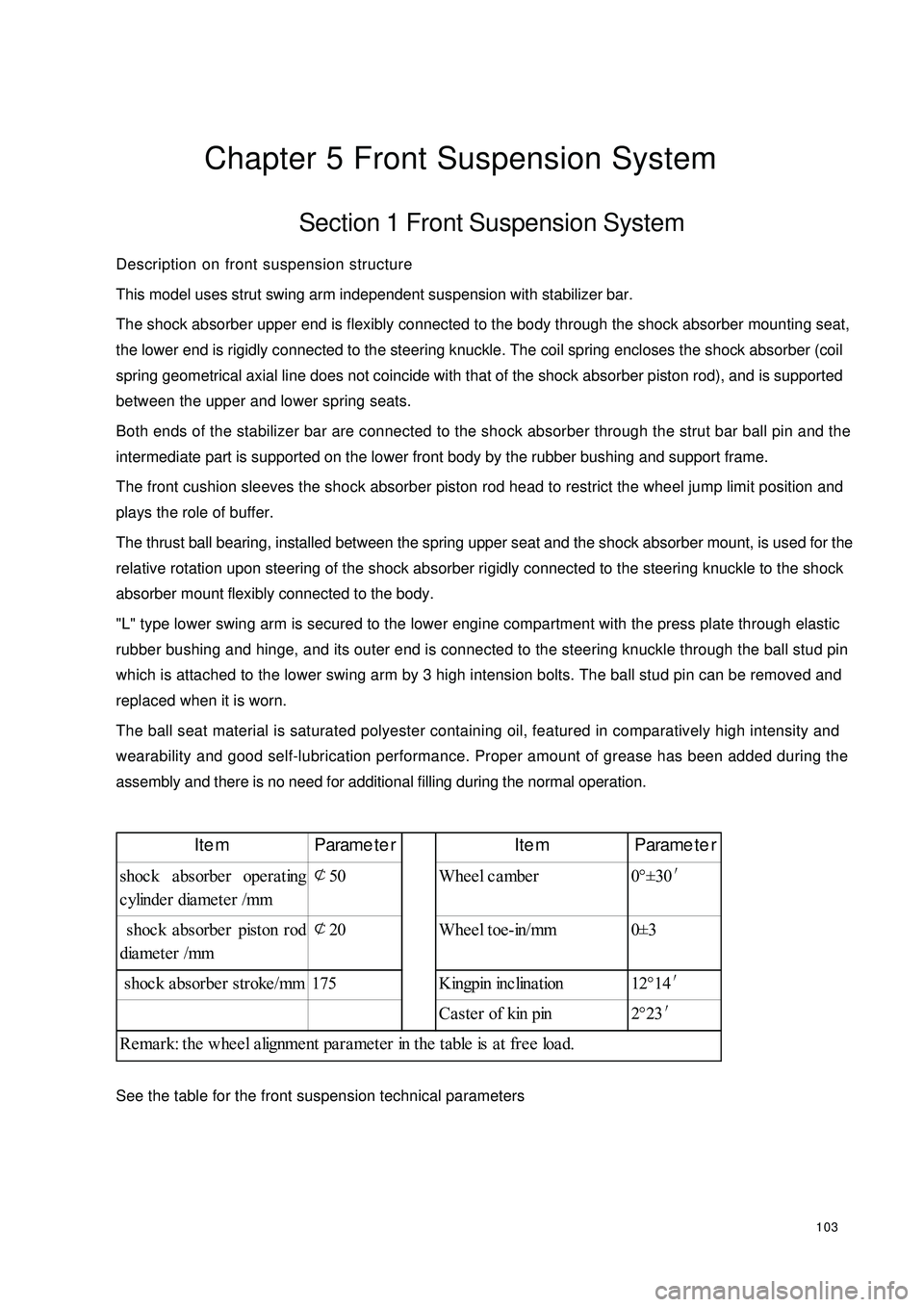
See the table for the front suspension technical parametersItem Parameter Item Parameter
shoc k a bsorbe r ope ra ting
cylinder diameter /mm¢
50 Wheel camber 0°±30′
shoc k a bsorbe r piston rod
diameter /mm¢
20 Wheel toe-in/mm 0±3
shoc k a bsorbe r stroke /mm 175 Kingpin inc lina tion 12°14′
Ca ste r of kin pin 2°23′
Remark: the wheel alignment parameter in the table is at free load.
Page 122 of 392
1155. Install the front stabilizer bar
Install stabilizer bar, 2 rubber bushings, the front stabilizer bar clamp and 4 bolts.
Torque: 50~60N.m
Notice:
(1) Align the inner rubber bushing with the mark on the stabilizer bar.
(2) The 4 bolts connecting the stabilizer bar clamp and front stabilizer bar support
frame welding assembly differ in length. The two short ones are close
6. Install stabilizer bar link rod assembly
(1) Attach the stabilizer bar link rod to the stabilizer bar with nuts.
Torque: 40~50 N.m
(2) Attach the stabilizer bar link rod to the front shock absorber bracket with nuts.
Torque: 40~50 N.mto engine.
Page 141 of 392

134On-vehicle inspection1. check the drive belt
Observe the drive belt for excessive wear and cordline wear. Replace the drive belt if necessary.
Hint: Cracks on the rib side of a belt are considered acceptable. If missing chunks from the
ribs are found on the drive belt, it should be replaced.
2. Bleed the power steering system
(1) Check the fluid level
(2) Jack up the front of the vehicle and make sure it is safe
(3) Rotate the steering wheel
a. With the engine off, turn the steering wheel from LH limit position to RH limit position several
times
(4) Release the jack and lower the vehicle
(5) Start the engine, run the engine at idle for a few minutes
(6) Turn the steering wheel to left or right limit position and keep it there for 2 - 3 seconds, then turn the
steering wheel to the opposite limit position and keep it there for 2 - 3 seconds. Repeat it several
times.
(7) Shut off the engine, check for foaming or emulsification in the reservoir. If there is foaming or
emulsification, bleed power steering system repeatedly
(8) Check the fluid level and for leakage
2. Check the fluid level
(1) Park the vehicle on a level surface
(2) With the engine stopped, check the fluid level in the reservoir. Add power steering fluid AT F
DEXRON if necessary.
Hint: the fluid level should be within the range of lowest level and highest level
(3) Check for foaming or emulsification, if there is, drain the power steering systemNormalAbnormal