Page 130 of 392
123Section 6 Left & Right Trailing Rod AssemblyComponents
Replacement1. Separate parking brake cable assembly
Remove the parking brake cable set bolt on trailing rod
2. Remove the trailing rod assembly
(1) Remove the bolt connecting the trailing rod assembly and rear brake assembly.
(2) Remove the bolt connecting the trailing rod assembly and vehicle body
3. The parts installation is in the reverse order of the removal
Caution:
(1) The torque of the bolt attaching the trailing rod assembly to the body: 81~ 96N.m
(2) The torque of the bolt attaching the trailing rod assembly to the rear brake assembly:
81~96N.m
(3) The above bolts shall be tightened to the specified torque at Non-load.
(4) Check rear wheel alignment, adjust it as necessaryLeft Brake
Manual Brake Cable Trailing Rod Bushing LR Trailing
Trailing Rod
Page 131 of 392
124Section 7 No. 1 Transverse Arm AssemblyComponents
Replacement1. Remove transverse arm assembly No. 1
(1) Remove the bolt connecting the No. 1 transverse arm assembly and rear brake assembly
(2) Remove the bolt connecting the No. 1 transverse arm assembly and vehicle body
2. Install the No. 1 transverse arm assembly
(1) The torque of the thread attaching the transverse arm to the body: 81~ 96N.m
(2) The torque of the thread attaching the transverse arm to the rear brake assembly: 81~96N.m
3. Check the rear wheel alignment, replace it as necessary.Pivot bracket
No. 1 Transverse arm
welding components
No. 1 Trailing arm bushing
Page 132 of 392

125Section 8 No. 2 Transverse Arm AssemblyComponents
Replacement1. Remove the strut rod mount component
Remove the strut rod mount component bolt on the No. 2 transverse arm assembly
2. Remove transverse arm assembly No. 2
(1) Remove the bolt connecting the No. 2 transverse arm assembly and rear brake assembly
(2) Remove the bolt connecting the No. 2 transverse arm assembly and vehicle body, rear wheel toe-in
adjust plate and rear wheel toe-adjust cam
3. Install No. 2 transverse arm assembly
(1) Use the nut, rear wheel toe-in adjust cam, rear wheel toe-in adjust plate to attach the No. 2 transverse
arm assembly to the body
(2) Install the No. 2 transverse arm assembly to the rear brake wheel hub. Torque : 81~96N.m
(3) Use the bolt to attach the strut rod component to the No. 2 transverse arm assembly. Torque :
22~25N.m
4. Check the rear wheel alignment, adjust it by adjusting the rear wheel toe-in adjust cam and adjust plate.
After the adjustment, tighten the bolts to torque 45~55N.mRear Stabilizer Bar
Strut Rod ComponentPivot BracketBody
Bottom PlateNo. 2 Transverse Arm
Welding Component
No. 2 Transverse Arm BushingRear Wheel Toe-in Adjust PlateRear Wheel Toe-in
Adjust Cam
Page 140 of 392

13311. Complete the service or replace the steering column assembly, the installation procedure is in the reverseorder of the removal
Notice:
(1) after the installation of the ignition lock core, check the steering lock operation: the
steering mechanism lock when the ignition key is pulled out; the steering mechanism
unlock when the key is inserted and turned to ACC position
(2)The torque of the 2 bolts and 2 nuts securing the steer column assembly:
16~26N.m
(3) connect the wire harness into place and make sure the wiring is good
(4) After properly adjust the positions of the combination switch and the steering column
upper and lower cover, tighten the 3 screws attaching the combination switch and the
steering column
(5) Torque of the universal joint yoke and steering gear assembly locking bolt: 22~34N.m
(6) Torque of the 4 set bolts of the dust cover and press plate: 16~26N.m
(7) When installing the steering wheel assembly, align the matchmarks of the steering wheel
and steering main shaft assembly,
Torque of the steering wheel specific inner torx bolt: 40~60N.m
(7) Check the air bag, it is not allowed to use the air bag parts from another vehicle
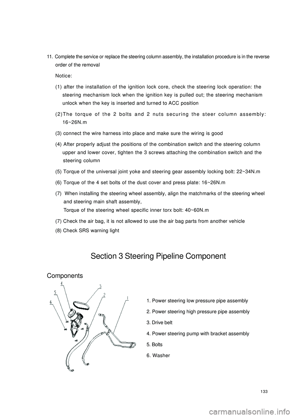
(8) Check SRS warning lightSection 3 Steering Pipeline ComponentComponents1. Power steering low pressure pipe assembly
2. Power steering high pressure pipe assembly
3. Drive belt
4. Power steering pump with bracket assembly
5. Bolts
6. Washer
Page 145 of 392

1383. Loosen the union thread of the high and low pressure pipes on the steering gear assembly
4. Remove the boot band and No. 1, No. 2 boots
5. Disconnect the power steering gear assembly from the steering column
Remove the steering gear pinion shaft spline lock bolt on the universal joint yoke
6. Remove power steering gear assembly
Remove 4 steering gear assembly set bolts, remove the power steering gear assembly
7. Installation is in the reverse order of the removal
Notice:
(1) Insert the steering gear pinion shaft spline into the spline hole of the universal joint
yoke, make sure that the positions of the notch of the steering gear pinion shaft and the
lock bolt of the universal joint yoke are correct
(2) Secure the power steering gear with 4 bolts, torque: 63~93N.m
(3) Tighten the steering gear pinion shaft spline lock bolt on the universal joint yoke, torque:
22~34N.m
(4) Tighten the 4 set bolts of the boot band and boot torque: 16~26N.m
(5) Install the union thread of the power steering high and low pressure pipe to the power
steering gear, torque: 19~33N.m
(6) Connect the tie rod ball stud pin with the steering knuckle, make sure that the mating
surface of the tie rod ball stud pin and the steering knuckle is clean, tighten the slot nut,
torque: 27~39N.m. Install the cotter pin, make sure of the correct installation
(7) Add appropriate amount of specified power steering fluid, bleed the power steering sys-
tem
(8) Check the power steering pipeline system for leakage
(9) Check the front wheel alignment and front wheel left and right limit turn angle, adjust the
toe in if necessary and tighten the tie rod lock nut
(10)Check the position of the steering wheel. It is required that the steering wheel spokes
are basically symmetrical when the vehicle is driven straight ahead, reassemble the steering
wheel if necessary
Page 153 of 392

14615. Remove the front disc
16. Installation is in the reverse order of the above-mentioned procedure
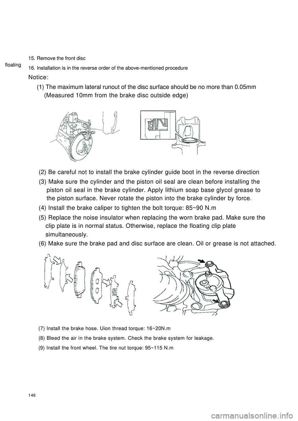
Notice:
(1) The maximum lateral runout of the disc surface should be no more than 0.05mm
(Measured 10mm from the brake disc outside edge)
(2) Be careful not to install the brake cylinder guide boot in the reverse direction
(3) Make sure the cylinder and the piston oil seal are clean before installing the
piston oil seal in the brake cylinder. Apply lithium soap base glycol grease to
the piston surface. Never rotate the piston into the brake cylinder by force.
(4) Install the brake caliper to tighten the bolt torque: 85~90 N.m
(5) Replace the noise insulator when replacing the worn brake pad. Make sure the
clip plate is in normal status. Otherwise, replace the floating clip plate
(6) Make sure the brake pad and disc surface are clean. Oil or grease is not attached.
(7) Install the brake hose. Uion thread torque: 16~20N.m
(8) Bleed the air in the brake system. Check the brake system for leakage.
(9) Install the front wheel. The tire nut torque: 95~115 N.msimultaneously.floating
Page 156 of 392

1499. Remove the parking brake lever accessory
10. Inspect shoe lining thickness
Standard thickness: 4.0mm
Minimum thickness: 1.0mm
Replace the shoe if the lining thickness is less than the minimum or seriously worn.
11.Inspect brake drum and brake shoe lining for proper contact
If the contact between brake drum and shoe lining is improper, repair the lining with a brake shoe
grinder or replace the brake shoe.
12. Check brake wheel cylinder
Check the cylinder wall, piston cup for damage
13. Install brake wheel cylinder accessory
(1) Apply lithium soap base glycol grease to 2 brake wheel cylinder cups and pistons
(2) Replace two new cups and boots
14. Install the brake wheel cylinder
Brake wheel cylinder set bolt torque: 9~13 N.m
15. Apply high temperature grease
Apply high temperature grease to the contact surface of anchor
plate hole and pin. Smear a thin layer grease to back plate.
16. Install parking brake swing arm and other accessories
17. Install brake shoe I, II
18. Install brake shoe return spring