Page 965 of 3000
EM–1562GR-FE ENGINE MECHANICAL – ENGINE UNIT
EM
NOTICE:
• When the contact surfaces are wet, wipe them
with an oil-free cloth before applying seal
packing.
• Install the chain cover within 3 minutes and
tighten the bolts within 15 minutes after
applying seal packing.
• Do not start the engine for at least 2 hours
after installing.
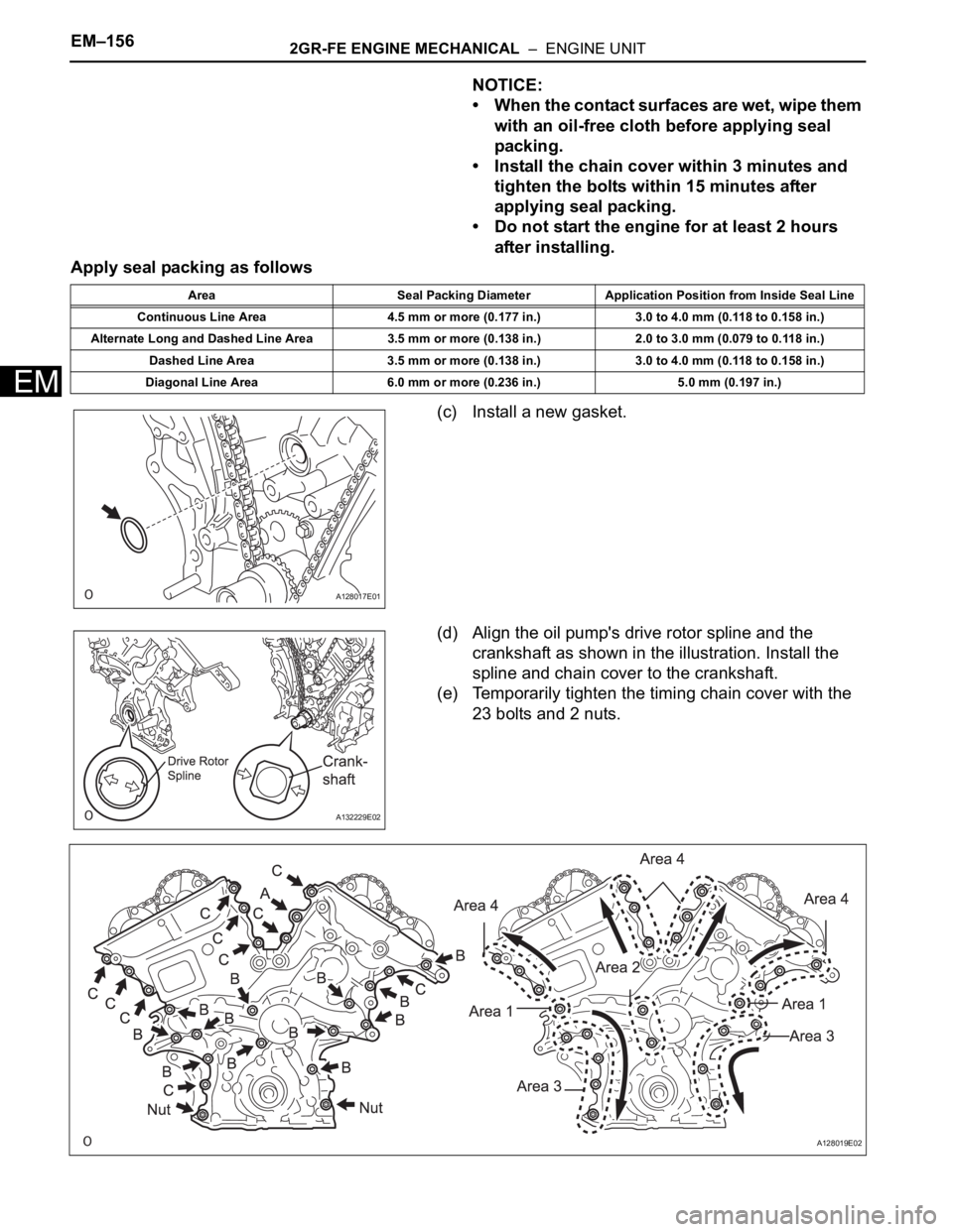
Apply seal packing as follows
(c) Install a new gasket.
(d) Align the oil pump's drive rotor spline and the
crankshaft as shown in the illustration. Install the
spline and chain cover to the crankshaft.
(e) Temporarily tighten the timing chain cover with the
23 bolts and 2 nuts.
Area Seal Packing Diameter Application Position from Inside Seal Line
Continuous Line Area 4.5 mm or more (0.177 in.) 3.0 to 4.0 mm (0.118 to 0.158 in.)
Alternate Long and Dashed Line Area 3.5 mm or more (0.138 in.) 2.0 to 3.0 mm (0.079 to 0.118 in.)
Dashed Line Area 3.5 mm or more (0.138 in.) 3.0 to 4.0 mm (0.118 to 0.158 in.)
Diagonal Line Area 6.0 mm or more (0.236 in.) 5.0 mm (0.197 in.)
A128017E01
A132229E02
A128019E02
Page 1103 of 3000
EM–1562GR-FE ENGINE MECHANICAL – ENGINE UNIT
EM
NOTICE:
• When the contact surfaces are wet, wipe them
with an oil-free cloth before applying seal
packing.
• Install the chain cover within 3 minutes and
tighten the bolts within 15 minutes after
applying seal packing.
• Do not start the engine for at least 2 hours
after installing.
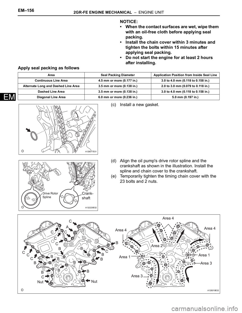
Apply seal packing as follows
(c) Install a new gasket.
(d) Align the oil pump's drive rotor spline and the
crankshaft as shown in the illustration. Install the
spline and chain cover to the crankshaft.
(e) Temporarily tighten the timing chain cover with the
23 bolts and 2 nuts.
Area Seal Packing Diameter Application Position from Inside Seal Line
Continuous Line Area 4.5 mm or more (0.177 in.) 3.0 to 4.0 mm (0.118 to 0.158 in.)
Alternate Long and Dashed Line Area 3.5 mm or more (0.138 in.) 2.0 to 3.0 mm (0.079 to 0.118 in.)
Dashed Line Area 3.5 mm or more (0.138 in.) 3.0 to 4.0 mm (0.118 to 0.158 in.)
Diagonal Line Area 6.0 mm or more (0.236 in.) 5.0 mm (0.197 in.)
A128017E01
A132229E02
A128019E02
Page 1296 of 3000
2GR-FE LUBRICATION – OIL PUMPLU–17
LU
NOTICE:
• When the contact surfaces are wet, wipe them
with an oil-free cloth before applying seal
packing.
• Install the chain cover within 3 minutes and
tighten the bolts within 15 minutes after
applying seal packing.
• Do not start the engine for at least 2 hours
after installing it.
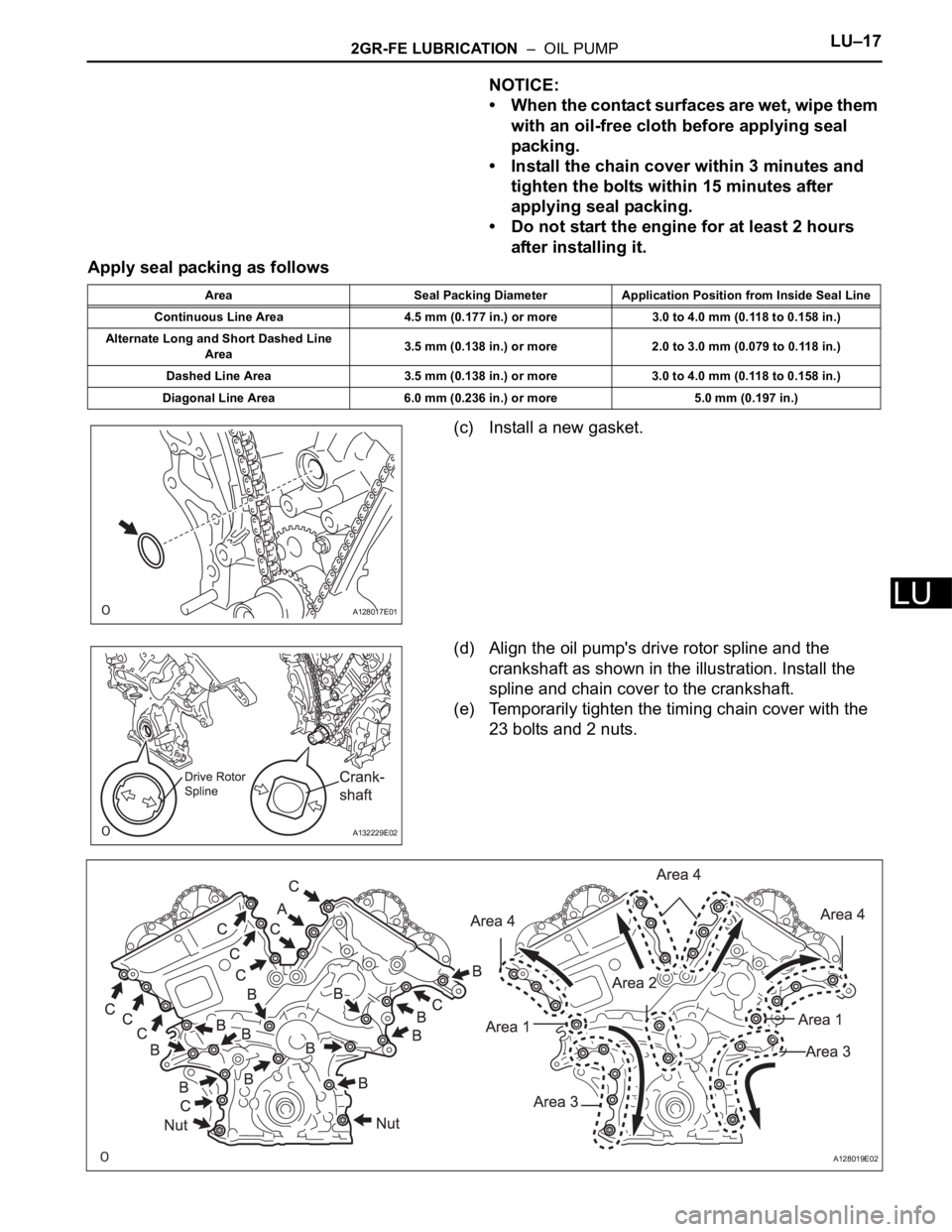
Apply seal packing as follows
(c) Install a new gasket.
(d) Align the oil pump's drive rotor spline and the
crankshaft as shown in the illustration. Install the
spline and chain cover to the crankshaft.
(e) Temporarily tighten the timing chain cover with the
23 bolts and 2 nuts.
Area Seal Packing Diameter Application Position from Inside Seal Line
Continuous Line Area 4.5 mm (0.177 in.) or more 3.0 to 4.0 mm (0.118 to 0.158 in.)
Alternate Long and Short Dashed Line
Area3.5 mm (0.138 in.) or more 2.0 to 3.0 mm (0.079 to 0.118 in.)
Dashed Line Area 3.5 mm (0.138 in.) or more 3.0 to 4.0 mm (0.118 to 0.158 in.)
Diagonal Line Area 6.0 mm (0.236 in.) or more 5.0 mm (0.197 in.)
A128017E01
A132229E02
A128019E02
Page 1309 of 3000
2GR-FE LUBRICATION – OIL PUMPLU–17
LU
NOTICE:
• When the contact surfaces are wet, wipe them
with an oil-free cloth before applying seal
packing.
• Install the chain cover within 3 minutes and
tighten the bolts within 15 minutes after
applying seal packing.
• Do not start the engine for at least 2 hours
after installing it.
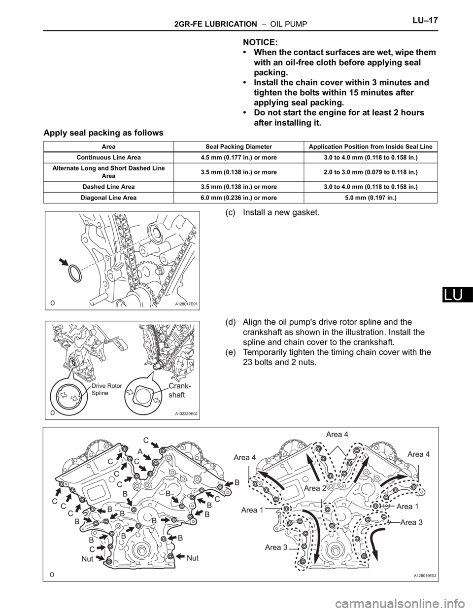
Apply seal packing as follows
(c) Install a new gasket.
(d) Align the oil pump's drive rotor spline and the
crankshaft as shown in the illustration. Install the
spline and chain cover to the crankshaft.
(e) Temporarily tighten the timing chain cover with the
23 bolts and 2 nuts.
Area Seal Packing Diameter Application Position from Inside Seal Line
Continuous Line Area 4.5 mm (0.177 in.) or more 3.0 to 4.0 mm (0.118 to 0.158 in.)
Alternate Long and Short Dashed Line
Area3.5 mm (0.138 in.) or more 2.0 to 3.0 mm (0.079 to 0.118 in.)
Dashed Line Area 3.5 mm (0.138 in.) or more 3.0 to 4.0 mm (0.118 to 0.158 in.)
Diagonal Line Area 6.0 mm (0.236 in.) or more 5.0 mm (0.197 in.)
A128017E01
A132229E02
A128019E02
Page 2604 of 3000
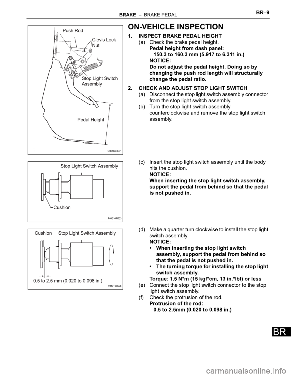
BRAKE – BRAKE PEDALBR–9
BR
ON-VEHICLE INSPECTION
1. INSPECT BRAKE PEDAL HEIGHT
(a) Check the brake pedal height.
Pedal height from dash panel:
150.3 to 160.3 mm (5.917 to 6.311 in.)
NOTICE:
Do not adjust the pedal height. Doing so by
changing the push rod length will structurally
change the pedal ratio.
2. CHECK AND ADJUST STOP LIGHT SWITCH
(a) Disconnect the stop light switch assembly connector
from the stop light switch assembly.
(b) Turn the stop light switch assembly
counterclockwise and remove the stop light switch
assembly.
(c) Insert the stop light switch assembly until the body
hits the cushion.
NOTICE:
When inserting the stop light switch assembly,
support the pedal from behind so that the pedal
is not pushed in.
(d) Make a quarter turn clockwise to install the stop light
switch assembly.
NOTICE:
• When inserting the stop light switch
assembly, support the pedal from behind so
that the pedal is not pushed in.
• The turning torque for installing the stop light
switch assembly.
Torque: 1.5 N*m (15 kgf*cm, 13 in.*lbf) or less
(e) Connect the stop light switch connector to the stop
light switch assembly.
(f) Check the protrusion of the rod.
Protrusion of the rod:
0.5 to 2.5mm (0.020 to 0.098 in.)
G024663E01
F045347E03
F043108E06