2007 TOYOTA SIENNA charging
[x] Cancel search: chargingPage 1377 of 3000
CH–282GR-FE CHARGING – GENERATOR
CH
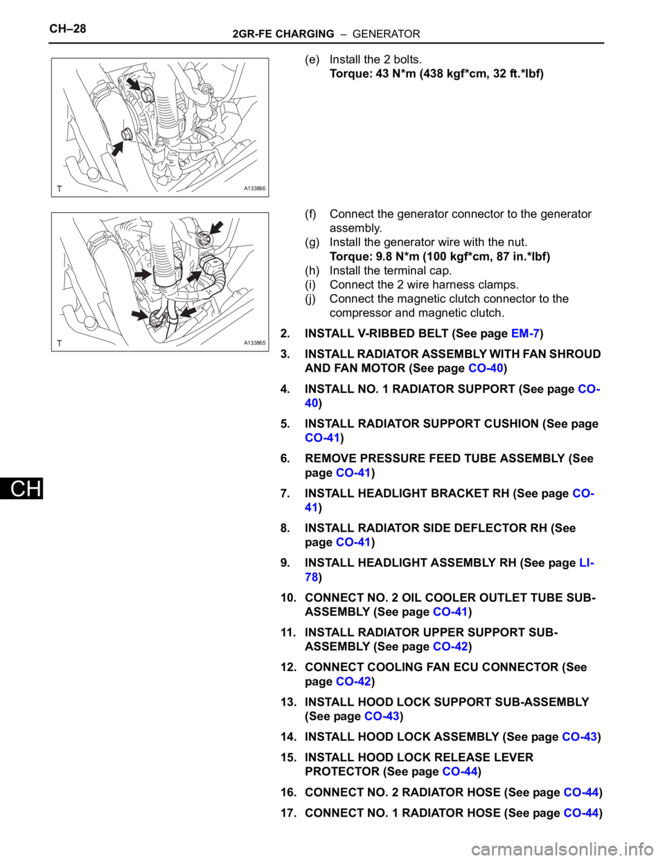
(e) Install the 2 bolts.
Torque: 43 N*m (438 kgf*cm, 32 ft.*lbf)
(f) Connect the generator connector to the generator
assembly.
(g) Install the generator wire with the nut.
Torque: 9.8 N*m (100 kgf*cm, 87 in.*lbf)
(h) Install the terminal cap.
(i) Connect the 2 wire harness clamps.
(j) Connect the magnetic clutch connector to the
compressor and magnetic clutch.
2. INSTALL V-RIBBED BELT (See page EM-7)
3. INSTALL RADIATOR ASSEMBLY WITH FAN SHROUD
AND FAN MOTOR (See page CO-40)
4. INSTALL NO. 1 RADIATOR SUPPORT (See page CO-
40)
5. INSTALL RADIATOR SUPPORT CUSHION (See page
CO-41)
6. REMOVE PRESSURE FEED TUBE ASSEMBLY (See
page CO-41)
7. INSTALL HEADLIGHT BRACKET RH (See page CO-
41)
8. INSTALL RADIATOR SIDE DEFLECTOR RH (See
page CO-41)
9. INSTALL HEADLIGHT ASSEMBLY RH (See page LI-
78)
10. CONNECT NO. 2 OIL COOLER OUTLET TUBE SUB-
ASSEMBLY (See page CO-41)
11. INSTALL RADIATOR UPPER SUPPORT SUB-
ASSEMBLY (See page CO-42)
12. CONNECT COOLING FAN ECU CONNECTOR (See
page CO-42)
13. INSTALL HOOD LOCK SUPPORT SUB-ASSEMBLY
(See page CO-43)
14. INSTALL HOOD LOCK ASSEMBLY (See page CO-43)
15. INSTALL HOOD LOCK RELEASE LEVER
PROTECTOR (See page CO-44)
16. CONNECT NO. 2 RADIATOR HOSE (See page CO-44)
17. CONNECT NO. 1 RADIATOR HOSE (See page CO-44)
A133866
A133865
Page 1378 of 3000
2GR-FE CHARGING – GENERATORCH–29
CH
18. CONNECT RADIATOR RESERVE TANK HOSE OR
PIPE (See page CO-44)
19. INSTALL NO. 1 AIR CLEANER INLET (See page EM-
59)
20. INSTALL FRONT BUMPER ENERGY ABSORBER
21. INSTALL FRONT BUMPER ASSEMBLY (See page ET-
9)
22. INSTALL BATTERY (See page EM-59)
23. INSTALL NO. 2 AIR CLEANER INLET (See page EM-
60)
24. ADD ENGINE COOLANT (See page CO-7)
25. INSPECT FOR COOLANT LEAK (See page CO-1)
26. ADD AUTOMATIC TRANSAXLE FLUID
27. CHECK AUTOMATIC TRANSAXLE FLUID (See page
AX-123)
28. INSTALL FRONT FENDER APRON SEAL RH (See
page EM-62)
29. INSTALL NO. 1 ENGINE UNDER COVER (See page
EM-63)
30. INSTALL FRONT WHEEL RH
Torque: 103 N*m (1050 kgf*cm, 76 ft.*lbf)
31. INSTALL V-BANK COVER SUB-ASSEMBLY (See
page EM-63)
32. VEHICLE PREPARATION FOR HEADLIGHT AIM
ADJUSTMENT (See page LI-71)
33. PREPARATION FOR HEADLIGHT AIMING (Using a
tester) (See page LI-71)
34. PREPARATION FOR HEADLIGHT AIMING (Using a
Screen) (See page LI-72)
35. HEADLIGHT AIMING INSPECTION (See page LI-74)
36. HEADLIGHT AIMING ADJUSTMENT (See page LI-75)
37. VEHICLE PREPARATION FOR FOG LIGHT AIM
ADJUSTMENT (w/ Fog Light) (See page LI-82)
38. PREPARATION FOR FOG LIGHT AIMING (Using a
Screen) (w/ Fog Light) (See page LI-83)
39. FOG LIGHT AIMING INSPECTION (w/ Fog Light) (See
page LI-74)
40. FOG LIGHT AIMING ADJUSTMENT (w/ Fog Light)
(See page LI-85)
Page 2385 of 3000
BC–18BRAKE CONTROL – ANTI-LOCK BRAKE SYSTEM
BC
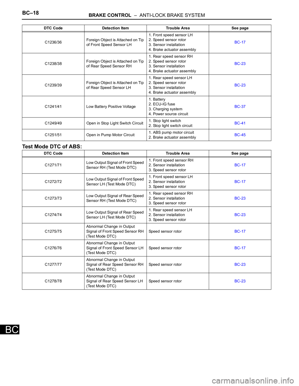
Test Mode DTC of ABS:
C1236/36Foreign Object is Attached on Tip
of Front Speed Sensor LH1. Front speed sensor LH
2. Speed sensor rotor
3. Sensor installation
4. Brake actuator assemblyBC-17
C1238/38Foreign Object is Attached on Tip
of Rear Speed Sensor RH1. Rear speed sensor RH
2. Speed sensor rotor
3. Sensor installation
4. Brake actuator assemblyBC-23
C1239/39Foreign Object is Attached on Tip
of Rear Speed Sensor LH1. Rear speed sensor LH
2. Speed sensor rotor
3. Sensor installation
4. Brake actuator assemblyBC-23
C1241/41 Low Battery Positive Voltage1. Battery
2. ECU-IG fuse
3. Charging system
4. Power source circuitBC-37
C1249/49 Open in Stop Light Switch Circuit1. Stop light switch
2. Stop light switch circuitBC-41
C1251/51 Open in Pump Motor Circuit1. ABS pump motor circuit
2. Brake actuator assemblyBC-45
DTC Code Detection Item Trouble Area See page
C1271/71Low Output Signal of Front Speed
Sensor RH (Test Mode DTC)1. Front speed sensor RH
2. Sensor installation
3. Speed sensor rotorBC-17
C1272/72Low Output Signal of Front Speed
Sensor LH (Test Mode DTC)1. Front speed sensor LH
2. Sensor installation
3. Speed sensor rotorBC-17
C1273/73Low Output Signal of Rear Speed
Sensor RH (Test Mode DTC)1. Rear speed sensor RH
2. Sensor installation
3. Speed sensor rotorBC-23
C1274/74Low Output Signal of Rear Speed
Sensor LH (Test Mode DTC)1. Rear speed sensor LH
2. Sensor installation
3. Speed sensor rotorBC-23
C1275/75Abnormal Change in Output
Signal of Front Speed Sensor RH
(Test Mode DTC)Speed sensor rotorBC-17
C1276/76Abnormal Change in Output
Signal of Front Speed Sensor LH
(Test Mode DTC)Speed sensor rotorBC-17
C1277/77Abnormal Change in Output
Signal of Rear Speed Sensor RH
(Test Mode DTC)Speed sensor rotorBC-23
C1278/78Abnormal Change in Output
Signal of Rear Speed Sensor LH
(Test Mode DTC)Speed sensor rotorBC-23 DTC Code Detection Item Trouble Area See page
Page 2400 of 3000
BRAKE CONTROL – ANTI-LOCK BRAKE SYSTEMBC–39
BC
DESCRIPTION
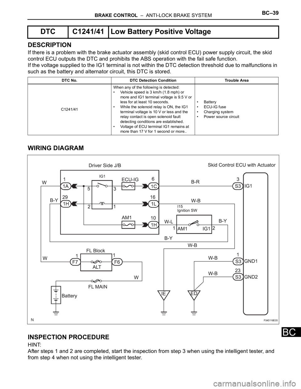
If there is a problem with the brake actuator assembly (skid control ECU) power supply circuit, the skid
control ECU outputs the DTC and prohibits the ABS operation with the fail safe function.
If the voltage supplied to the IG1 terminal is not within the DTC detection threshold due to malfunctions in
such as the battery and alternator circuit, this DTC is stored.
WIRING DIAGRAM
INSPECTION PROCEDURE
HINT:
After steps 1 and 2 are completed, start the inspection from step 3 when using the intelligent tester, and
from step 4 when not using the intelligent tester.
DTC C1241/41 Low Battery Positive Voltage
DTC No. DTC Detection Condition Trouble Area
C1241/41When any of the following is detected:
• Vehicle speed is 3 km/h (1.8 mph) or
more and IG1 terminal voltage is 9.5 V or
less for at least 10 seconds.
• While the solenoid relay is ON, the IG1
terminal voltage is 10 V or less and the
relay contact is open solenoid fault
detecting conditions are established.
• Voltage of ECU terminal IG1 remains at
more than 17 V for 1 second or more..• Battery
•ECU-IG fuse
• Charging system
• Power source circuit
F045116E05
Page 2401 of 3000
BC–40BRAKE CONTROL – ANTI-LOCK BRAKE SYSTEM
BC
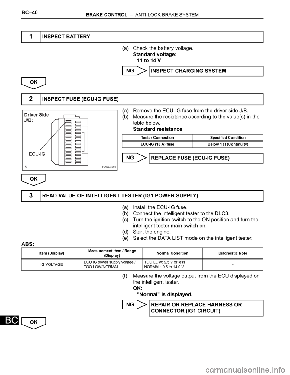
(a) Check the battery voltage.
Standard voltage:
11 to 14 V
NG
OK
(a) Remove the ECU-IG fuse from the driver side J/B.
(b) Measure the resistance according to the value(s) in the
table below.
Standard resistance
NG
OK
(a) Install the ECU-IG fuse.
(b) Connect the intelligent tester to the DLC3.
(c) Turn the ignition switch to the ON position and turn the
intelligent tester main switch on.
(d) Start the engine.
(e) Select the DATA LIST mode on the intelligent tester.
ABS:
(f) Measure the voltage output from the ECU displayed on
the intelligent tester.
OK:
"Normal" is displayed.
NG
OK
1INSPECT BATTERY
INSPECT CHARGING SYSTEM
2INSPECT FUSE (ECU-IG FUSE)
F045093E04
Tester Connection Specified Condition
ECU-IG (10 A) fuse Below 1
(Continuity)
REPLACE FUSE (ECU-IG FUSE)
3READ VALUE OF INTELLIGENT TESTER (IG1 POWER SUPPLY)
Item (Display)Measurement Item / Range
(Display)Normal Condition Diagnostic Note
IG VOLTAGEECU IG power supply voltage /
TOO LOW/NORMALTOO LOW: 9.5 V or less
NORMAL: 9.5 to 14.0 V-
REPAIR OR REPLACE HARNESS OR
CONNECTOR (IG1 CIRCUIT)
Page 2411 of 3000
BC–50BRAKE CONTROL – ANTI-LOCK BRAKE SYSTEM
BC
INSPECTION PROCEDURE
(a) Check the skid control ECU connector's connecting
condition.
OK:
The connector should be securely connected.
NG
OK
(a) Check the battery voltage.
Standard voltage:
11 to 14 V
NG
OK
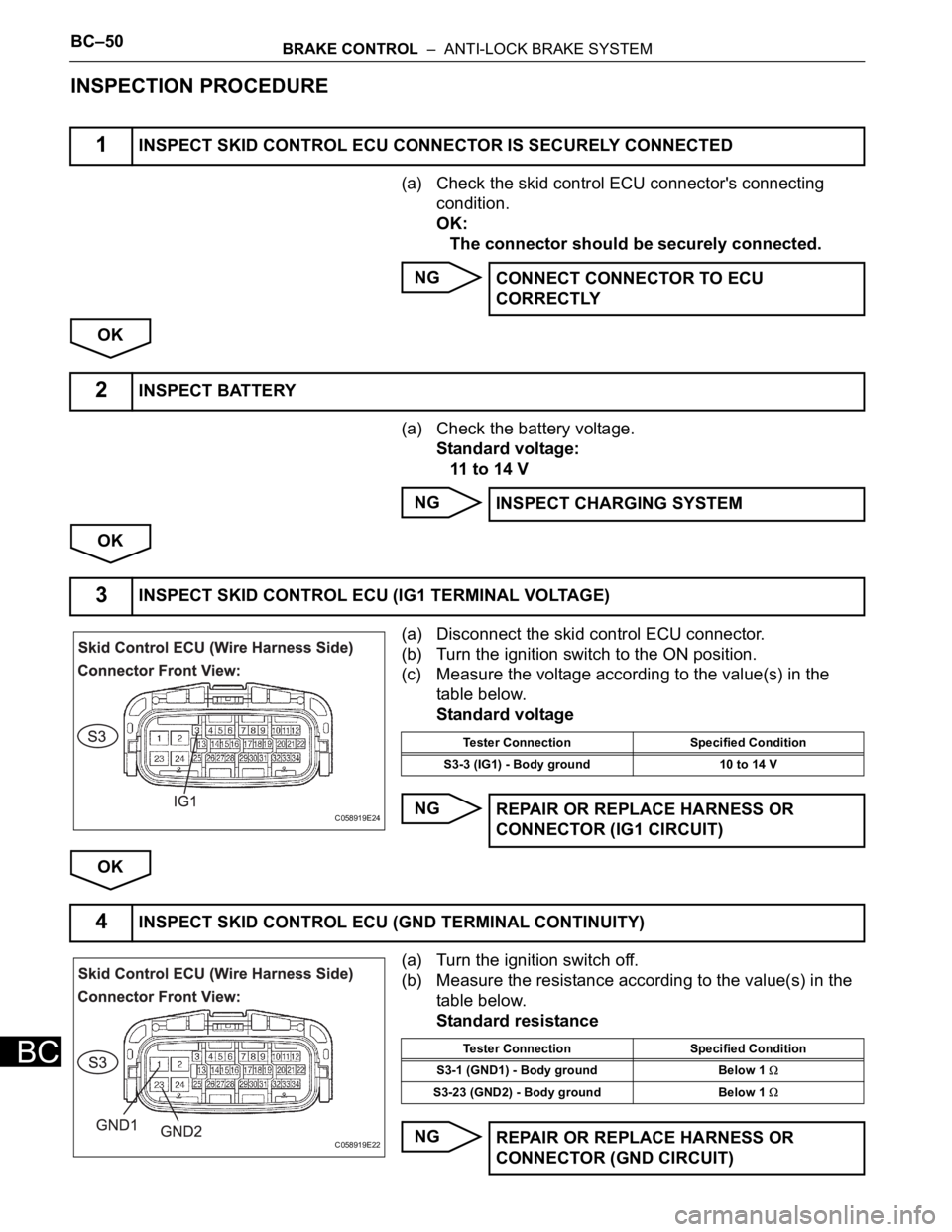
(a) Disconnect the skid control ECU connector.
(b) Turn the ignition switch to the ON position.
(c) Measure the voltage according to the value(s) in the
table below.
Standard voltage
NG
OK
(a) Turn the ignition switch off.
(b) Measure the resistance according to the value(s) in the
table below.
Standard resistance
NG
1INSPECT SKID CONTROL ECU CONNECTOR IS SECURELY CONNECTED
CONNECT CONNECTOR TO ECU
CORRECTLY
2INSPECT BATTERY
INSPECT CHARGING SYSTEM
3INSPECT SKID CONTROL ECU (IG1 TERMINAL VOLTAGE)
C058919E24
Tester Connection Specified Condition
S3-3 (IG1) - Body ground 10 to 14 V
REPAIR OR REPLACE HARNESS OR
CONNECTOR (IG1 CIRCUIT)
4INSPECT SKID CONTROL ECU (GND TERMINAL CONTINUITY)
C058919E22
Tester Connection Specified Condition
S3-1 (GND1) - Body ground Below 1
S3-23 (GND2) - Body ground Below 1
REPAIR OR REPLACE HARNESS OR
CONNECTOR (GND CIRCUIT)
Page 2416 of 3000
BRAKE CONTROL – ANTI-LOCK BRAKE SYSTEMBC–55
BC
INSPECTION PROCEDURE
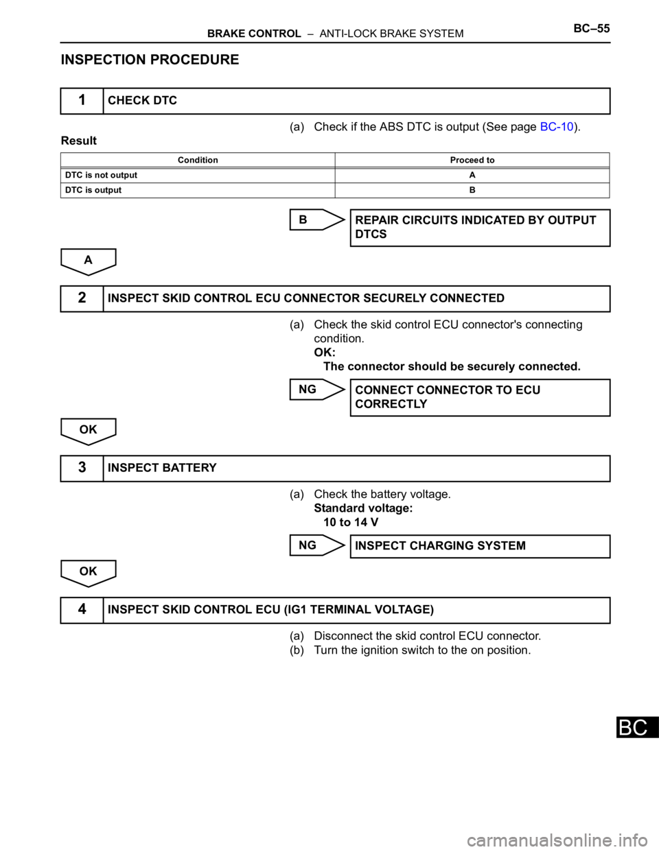
(a) Check if the ABS DTC is output (See page BC-10).
Result
B
A
(a) Check the skid control ECU connector's connecting
condition.
OK:
The connector should be securely connected.
NG
OK
(a) Check the battery voltage.
Standard voltage:
10 to 14 V
NG
OK
(a) Disconnect the skid control ECU connector.
(b) Turn the ignition switch to the on position.
1CHECK DTC
Condition Proceed to
DTC is not outputA
DTC is outputB
REPAIR CIRCUITS INDICATED BY OUTPUT
DTCS
2INSPECT SKID CONTROL ECU CONNECTOR SECURELY CONNECTED
CONNECT CONNECTOR TO ECU
CORRECTLY
3INSPECT BATTERY
INSPECT CHARGING SYSTEM
4INSPECT SKID CONTROL ECU (IG1 TERMINAL VOLTAGE)
Page 2452 of 3000
BC–90BRAKE CONTROL – VEHICLE STABILITY CONTROL SYSTEM
BC
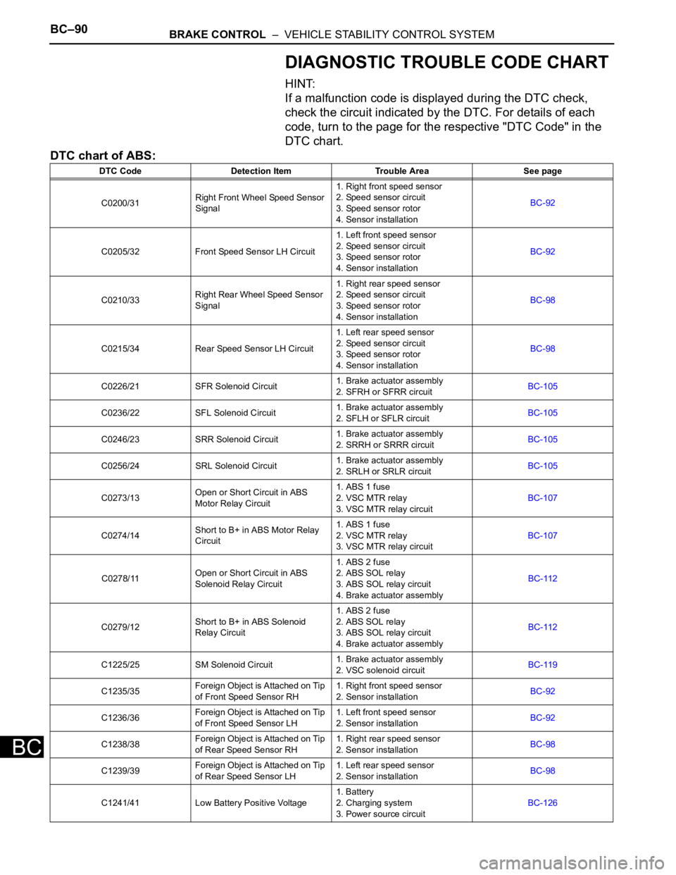
DIAGNOSTIC TROUBLE CODE CHART
HINT:
If a malfunction code is displayed during the DTC check,
check the circuit indicated by the DTC. For details of each
code, turn to the page for the respective "DTC Code" in the
DTC chart.
DTC chart of ABS:
DTC Code Detection Item Trouble Area See page
C0200/31Right Front Wheel Speed Sensor
Signal1. Right front speed sensor
2. Speed sensor circuit
3. Speed sensor rotor
4. Sensor installationBC-92
C0205/32 Front Speed Sensor LH Circuit1. Left front speed sensor
2. Speed sensor circuit
3. Speed sensor rotor
4. Sensor installationBC-92
C0210/33Right Rear Wheel Speed Sensor
Signal1. Right rear speed sensor
2. Speed sensor circuit
3. Speed sensor rotor
4. Sensor installationBC-98
C0215/34 Rear Speed Sensor LH Circuit1. Left rear speed sensor
2. Speed sensor circuit
3. Speed sensor rotor
4. Sensor installationBC-98
C0226/21 SFR Solenoid Circuit1. Brake actuator assembly
2. SFRH or SFRR circuitBC-105
C0236/22 SFL Solenoid Circuit1. Brake actuator assembly
2. SFLH or SFLR circuitBC-105
C0246/23 SRR Solenoid Circuit1. Brake actuator assembly
2. SRRH or SRRR circuitBC-105
C0256/24 SRL Solenoid Circuit1. Brake actuator assembly
2. SRLH or SRLR circuitBC-105
C0273/13Open or Short Circuit in ABS
Motor Relay Circuit1. ABS 1 fuse
2. VSC MTR relay
3. VSC MTR relay circuitBC-107
C0274/14Short to B+ in ABS Motor Relay
Circuit1. ABS 1 fuse
2. VSC MTR relay
3. VSC MTR relay circuitBC-107
C0278/11Open or Short Circuit in ABS
Solenoid Relay Circuit1. ABS 2 fuse
2. ABS SOL relay
3. ABS SOL relay circuit
4. Brake actuator assemblyBC-112
C0279/12Short to B+ in ABS Solenoid
Relay Circuit1. ABS 2 fuse
2. ABS SOL relay
3. ABS SOL relay circuit
4. Brake actuator assemblyBC-112
C1225/25 SM Solenoid Circuit1. Brake actuator assembly
2. VSC solenoid circuitBC-119
C1235/35Foreign Object is Attached on Tip
of Front Speed Sensor RH1. Right front speed sensor
2. Sensor installationBC-92
C1236/36Foreign Object is Attached on Tip
of Front Speed Sensor LH1. Left front speed sensor
2. Sensor installationBC-92
C1238/38Foreign Object is Attached on Tip
of Rear Speed Sensor RH1. Right rear speed sensor
2. Sensor installationBC-98
C1239/39Foreign Object is Attached on Tip
of Rear Speed Sensor LH1. Left rear speed sensor
2. Sensor installationBC-98
C1241/41 Low Battery Positive Voltage1. Battery
2. Charging system
3. Power source circuitBC-126