2007 TOYOTA SIENNA wheel
[x] Cancel search: wheelPage 218 of 3000

SS–24SERVICE SPECIFICATIONS – U151E AUTOMATIC TRANSAXLE
SS
U151E AUTOMATIC TRANSAXLE
SERVICE DATA
Line pressure (Wheel locked)
Engine
idling
D position
370 to 410 kPa (3.8 to 4.2 kgf*cm
2, 54 to 60 psi)
R position
670 to 740 kPa (6.8 to 7.5 kgf*cm
2, 97 to 106 psi)
AT s t a l l
(Throttle
valve fully
opened)
D position
931 to 1,031 kPa (9.5 to 10.5 kgf*cm
2, 135 to 150 psi)
R position
1,768 to 1,968 kPa (18.0 to 20 kgf*cm
2, 256 to 285 psi)
Engine stall revolution D and R
positions2,300 +- 150 rpm
Time lag N
D
positionLess than 1.2 seconds
N
R
positionLess than 1.5 seconds
Engine idle speed (A/C OFF) N position 650 +- 50 rpm
Drive plate runout Max. 0.20 mm (0.0079 in.)
Torque converter runout Max. 0.30 mm (0.0118 in.)
Differential oil seal drive in depth LH side 0 +- 0.5 mm (0 +- 0.020 in.)
RH side 0 +- 0.5 mm (0 +- 0.020 in.)
TIRE: 215/65R16
Shift schedule
Throttle valve fully open
(Normal)
1
2 47 to 54 km/h (29 to 34 mph)
2
3 94 to 100 km/h (58 to 62 mph)
3
4 152 to 163 km/h (94 to 101 mph)
4
5 227 to 238 km/h (141 to 148 mph)
5
4 218 to 229 km/h (135 to 142 mph)
4
3 146 to 157 km/h (91 to 98 mph)
3
2 89 to 95 km/h (55 to 59 mph)
2
1 37 to 43 km/h (23 to 27 mph)
Throttle valve fully closed
(Normal)4
5 66 to 72 km/h (41 to 45 mph)
5
4 38 to 44 km/h (24 to 27 mph)
Throttle valve fully open
(Cold)
1
2 29 to 36 km/h (18 to 22 mph)
2
3 47 to 53 km/h (29 to 33 mph)
3
4 77 to 83 km/h (48 to 52 mph)
4
3 72 to 78 km/h (45 to 48 mph)
3
2 42 to 48 km/h (26 to 30 mph)
2
1 23 to 29 km/h (14 to 18 mph)
Throttle valve fully open
(Failure)
1
3 29 to 36 km/h (18 to 22 mph)
3
4 77 to 83 km/h (48 to 52 mph)
4
3 72 to 78 km/h (45 to 48 mph)
3
1 23 to 29 km/h (14 to 18 mph)
Page 224 of 3000

SERVICE SPECIFICATIONS – U151F AUTOMATIC TRANSAXLESS–31
SS
U151F AUTOMATIC TRANSAXLE
SERVICE DATA
Line pressure (Wheel locked)
Engine
idling
D position
370 to 410 kPa (3.8 to 4.2 kgf*cm
2, 54 to 60 psi)
R position
670 to 740 kPa (6.8 to 7.5 kgf*cm
2, 97 to 106 psi)
AT s t a l l
(Throttle
valve fully
opened)
D position
931 to 1,031 kPa (9.5 to 10.5 kgf*cm
2, 135 to 150 psi)
R position
1,768 to 1,968 kPa (18.0 to 20 kgf*cm
2, 256 to 285 psi)
Engine stall revolution D and R
positions2,550 +- 150 rpm
Time lag N
D
positionLess than 1.2 seconds
N
R
positionLess than 1.5 seconds
Engine idle speed (A/C OFF) N position 650 +- 50 rpm
Drive plate runout Max. 0.20 mm (0.0079 in.)
Torque converter runout Max. 0.30 mm (0.0118 in.)
Differential oil seal drive in depth LH side 0 +- 0.5 mm (0 +- 0.020 in.)
RH side 6.0 +- 0.236 mm (0 +- 0.020 in.)
Shift schedule
Throttle valve fully open
(Normal)
1
2 45 to 52 km/h (28 to 32 mph)
2
3 90 to 97 km/h (56 to 60 mph)
3
4 146 to 157 km/h (91 to 98 mph)
4
5 218 to 229 km/h (135 to 142 mph)
5
4 209 to 221 km/h (130 to 137 mph)
4
3 141 to 151 km/h (88 to 94 mph)
3
2 85 to 91 km/h (52 to 57 mph)
2
1 36 to 41 km/h (22 to 25 mph)
Throttle valve fully closed
(Normal)4
5 63 to 69 km/h (39 to 43 mph)
5
4 37 to 42 km/h (23 to 26 mph)
Throttle valve fully open
(Cold)
1
2 28 to 34 km/h (17 to 21 mph)
2
3 45 to 51 km/h (28 to 32 mph)
4
3 74 to 80 km/h (46 to 50 mph)
4
3 69 to 75 km/h (43 to 47 mph)
3
2 41 to 46 km/h (25 to 29 mph)
2
1 22 to 28 km/h (14 to 17 mph)
Throttle valve fully open
(Failure)
1
3 28 to 34 km/h (17 to 21 mph)
3
4 74 to 80 km/h (46 to 50 mph)
4
3 69 to 75 km/h (43 to 47 mph)
3
1 22 to 28 km/h (14 to 17 mph)
Page 289 of 3000
INSTRUMENT PANEL – INSTRUMENT PANEL SAFETY PADIP–5
IP
REMOVAL
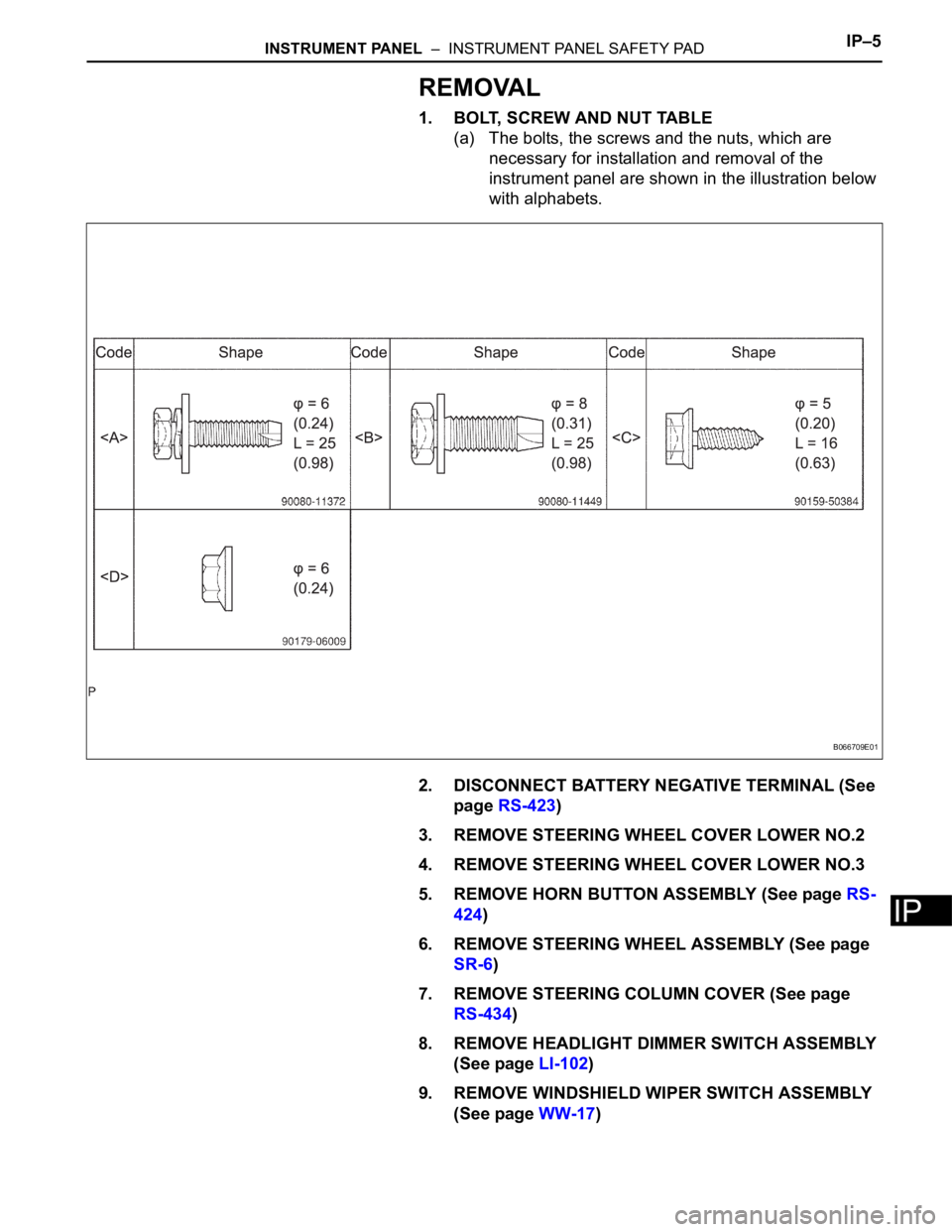
1. BOLT, SCREW AND NUT TABLE
(a) The bolts, the screws and the nuts, which are
necessary for installation and removal of the
instrument panel are shown in the illustration below
with alphabets.
2. DISCONNECT BATTERY NEGATIVE TERMINAL (See
page RS-423)
3. REMOVE STEERING WHEEL COVER LOWER NO.2
4. REMOVE STEERING WHEEL COVER LOWER NO.3
5. REMOVE HORN BUTTON ASSEMBLY (See page RS-
424)
6. REMOVE STEERING WHEEL ASSEMBLY (See page
SR-6)
7. REMOVE STEERING COLUMN COVER (See page
RS-434)
8. REMOVE HEADLIGHT DIMMER SWITCH ASSEMBLY
(See page LI-102)
9. REMOVE WINDSHIELD WIPER SWITCH ASSEMBLY
(See page WW-17)
B066709E01
Page 318 of 3000

2GR-FE ENGINE CONTROL SYSTEM – SFI SYSTEMES–1
ES
SFI SYSTEM
PRECAUTION
1. INITIALIZATION
NOTICE:
• Perform RESET MEMORY (AT initialization) when
replacing the automatic transaxle assembly, engine
assembly or ECM (See page AX-16).
• Perform REGISTRATION (VIN registration) when
replacing the ECM (See page ES-15).
HINT:
Initialization cannot be completed by only removing the
battery.
2. FOR USING INTELLIGENT TESTER
CAUTION:
Observe the following items for safety reasons:
• Before using the tester, read the instruction
manual.
• Prevent the tester cable from being caught on the
pedals, shift lever and steering wheel when
driving with the tester connected to the vehicle.
• When driving the vehicle for testing purposes
using the tester, two persons are required. One is
for driving the vehicle, and the other operates the
tester.
3. FOR USING BATTERY DURING INSPECTION
(a) While using the battery during inspection, do not
bring the positive and negative tester probes too
close to each other as a short circuit may occur.
4. COOLING FAN SYSTEM
NOTICE:
• When the ignition switch is turned off and the engine
temperature is high, the cooling fans may operate for
approximately 3 minutes.
• After turning the ignition switch off, keep hands and
objects away from the fans when they are operating.
HINT:
If all of the following are met for a certain period of time during
a few minute period immediately before the engine is
stopped, the electric fans will continue to operate for 3
minutes after the engine is stopped. This is performed to
ensure restartability and stabilize idle speed.
– The intelligent tester indicates a very high coolant
temperature.
– The intelligent tester indicates a high outside air
temperature.
– The vehicle has been driven under high load (driving on an
uphill or equivalent).
The following sensors are used for this control:
– Coolant temperature sensor
– Outside air temperature sensor
–MAF sensor
– Vehicle speed sensors
Page 584 of 3000
2GR-FE ENGINE CONTROL SYSTEM – SFI SYSTEMES–291
ES
DESCRIPTION
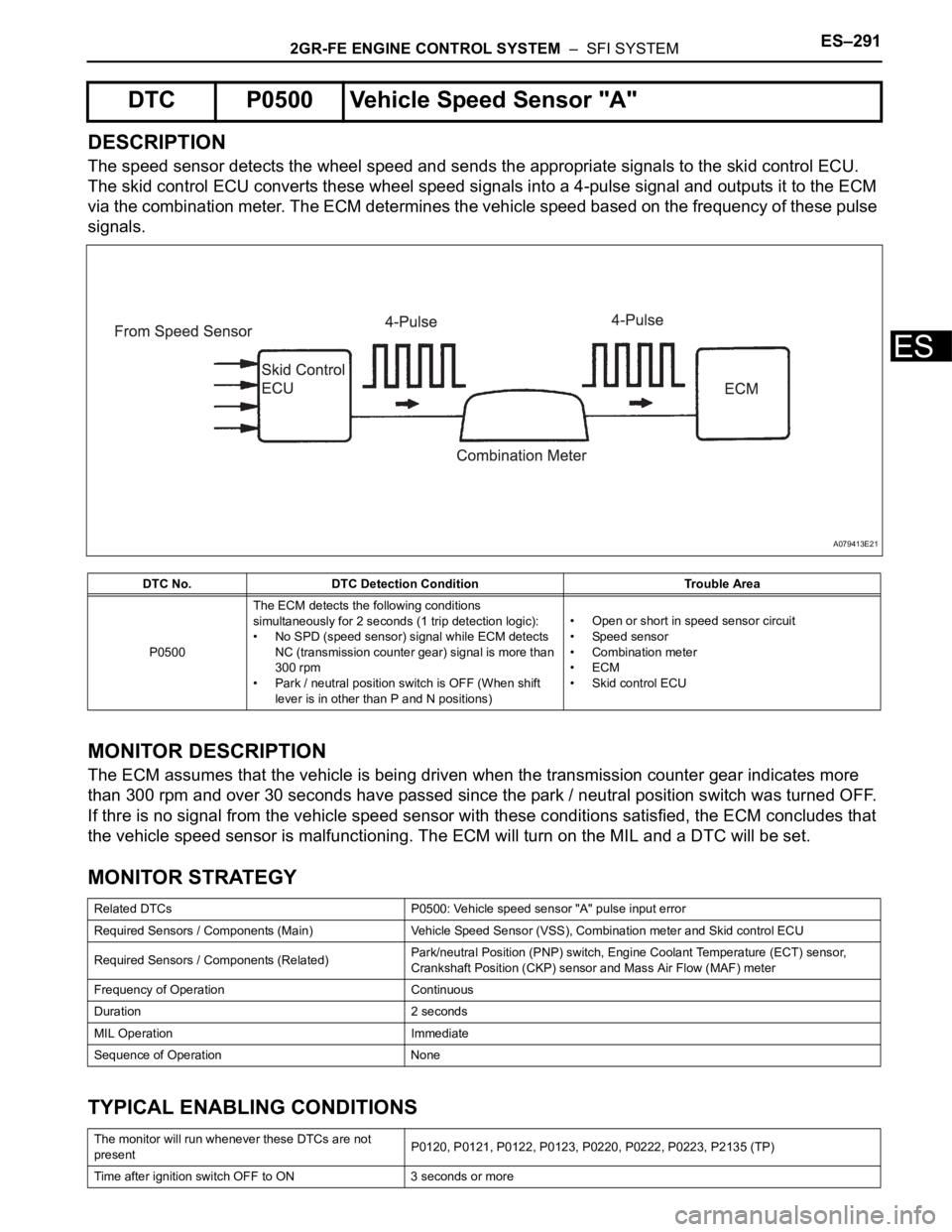
The speed sensor detects the wheel speed and sends the appropriate signals to the skid control ECU.
The skid control ECU converts these wheel speed signals into a 4-pulse signal and outputs it to the ECM
via the combination meter. The ECM determines the vehicle speed based on the frequency of these pulse
signals.
MONITOR DESCRIPTION
The ECM assumes that the vehicle is being driven when the transmission counter gear indicates more
than 300 rpm and over 30 seconds have passed since the park / neutral position switch was turned OFF.
If thre is no signal from the vehicle speed sensor with these conditions satisfied, the ECM concludes that
the vehicle speed sensor is malfunctioning. The ECM will turn on the MIL and a DTC will be set.
MONITOR STRATEGY
TYPICAL ENABLING CONDITIONS
DTC P0500 Vehicle Speed Sensor "A"
DTC No. DTC Detection Condition Trouble Area
P0500The ECM detects the following conditions
simultaneously for 2 seconds (1 trip detection logic):
• No SPD (speed sensor) signal while ECM detects
NC (transmission counter gear) signal is more than
300 rpm
• Park / neutral position switch is OFF (When shift
lever is in other than P and N positions)• Open or short in speed sensor circuit
• Speed sensor
• Combination meter
•ECM
• Skid control ECU
Related DTCs P0500: Vehicle speed sensor "A" pulse input error
Required Sensors / Components (Main) Vehicle Speed Sensor (VSS), Combination meter and Skid control ECU
Required Sensors / Components (Related)Park/neutral Position (PNP) switch, Engine Coolant Temperature (ECT) sensor,
Crankshaft Position (CKP) sensor and Mass Air Flow (MAF) meter
Frequency of Operation Continuous
Duration 2 seconds
MIL Operation Immediate
Sequence of Operation None
The monitor will run whenever these DTCs are not
presentP0120, P0121, P0122, P0123, P0220, P0222, P0223, P2135 (TP)
Time after ignition switch OFF to ON 3 seconds or more
A079413E21
Page 587 of 3000
ES–2942GR-FE ENGINE CONTROL SYSTEM – SFI SYSTEM
ES
(a) Shift the transmission gear selector lever to the neutral
position.
(b) Jack up the vehicle.
(c) Turn the ignition switch to the ON position.
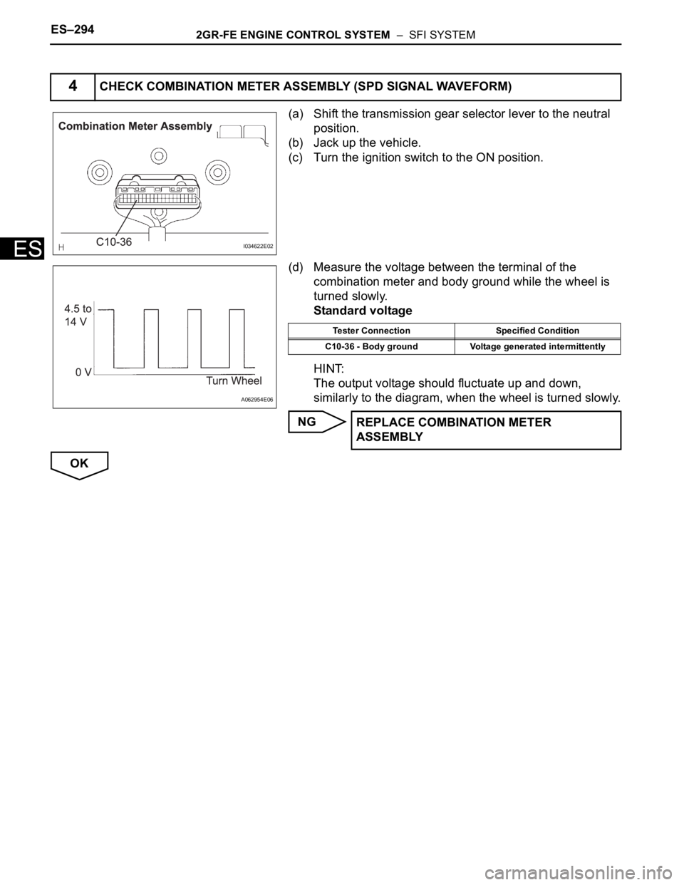
(d) Measure the voltage between the terminal of the
combination meter and body ground while the wheel is
turned slowly.
Standard voltage
HINT:
The output voltage should fluctuate up and down,
similarly to the diagram, when the wheel is turned slowly.
NG
OK
4CHECK COMBINATION METER ASSEMBLY (SPD SIGNAL WAVEFORM)
I034622E02
A062954E06
Tester Connection Specified Condition
C10-36 - Body ground Voltage generated intermittently
REPLACE COMBINATION METER
ASSEMBLY
Page 814 of 3000

ES–342GR-FE ENGINE CONTROL SYSTEM – SFI SYSTEM
ES
VPA (E4-18) - EPA (E4-20) L-Y - R-BAccelerator pedal position
sensor signal (for engine
control)Ignition switch ON, Accelerator
pedal fully depressed2.6 to 4.5 V
VPA2 (E4-19) - EPA2 (E4-21) W-R - LGAccelerator pedal position
sensor signal (for sensor
malfunction detection)Ignition switch ON, Accelerator
pedal fully released1.2 to 2.0 V
VPA2 (E4-19) - EPA2 (E4-21) W-R - LGAccelerator pedal position
sensor signal (for sensor
malfunction detection)Ignition switch ON, Accelerator
pedal fully depressed3.4 to 5.0 V
EPA (E4-20) - VPA (E4-18) R-B - L-YAccelerator pedal position
sensor signal (for engine
control)Ignition switch ON, Accelerator
pedal fully released0.5 to 1.1 V
EPA (E4-20) - VPA (E4-18) R-B - L-YAccelerator pedal position
sensor signal (for engine
control)Ignition switch ON, Accelerator
pedal fully depressed2.6 to 4.5 V
EPA2 (E4-21) - VPA2 (E4-19) LG - W-RAccelerator pedal position
sensor signal (for sensor
malfunction detection)Ignition switch ON, Accelerator
pedal fully released1.2 to 2.0 V
EPA2 (E4-21) - VPA2 (E4-19) LG - W-RAccelerator pedal position
sensor signal (for sensor
malfunction detection)Ignition switch ON, Accelerator
pedal fully depressed3.4 to 5.0 V
PPMP (E4-22) - E2 (E9-28) B - BRPressure sensor signal
(built into pump module)Ignition switch ON 3 to 3.6 V
TC (E4-23) - E1 (E11-1) P-B - BR Terminal TC of DLC3 Ignition switch ON 9 to 14 V
VCPA (E4-26) - EPA (E4-20) GR-R - R-BPower source of
accelerator pedal position
sensor (for VPA)Ignition switch ON 4.5 to 5.0 V
VCP2 (E4-27) - EPA2 (E4-21) B-R - LGPower source of
accelerator pedal position
sensor (for VPA2)Ignition switch ON 4.5 to 5.0 V
TACH (E5-1) - E1 (E11-1) B-O - BREngine speed signal (for
combination meter)IdlingPulse generation
(see waveform 11)
SPD (E5-8) - E1 (E11-1) V-W - BRVehicle speed signal from
combination meterIgnition switch ON, driving wheel
rotated slowlyPulse generation
(see waveform 8)
W (E5-30) - E1 (E11-1) B-Y - BRMalfunction Indicator
Lamp (MIL) operation
signalIgnition switch ON Below 3.0 V
W (E5-30) - E1 (E11-1) B-Y - BRMalfunction Indicator
Lamp (MIL) operation
signalIdling 9 to 14 V
CANH (E5-33) - CANL (E5-
34)B - WCAN communication
circuitIgnition switch off 54 to 69
CANL (E5-34) - CANH (E5-
33)W - BCAN communication
circuitIgnition switch off 54 to 69
E1 (E11-1) - Body ground BR - -Earth (ground) circuit of
ECMAlways Below 1 V
#10 (E11-2) - E01 (E9-7)
#20 (E11-3) - E01 (E9-7)
#30 (E11-4) - E01 (E9-7)
#40 (E11-5) - E01 (E9-7)
#50 (E11-6) - E01 (E9-7)
#60 (E11-7) - E01 (E9-7)L - W-B
R - W-B
B - W-B
W - W-B
B-W - W-B
G - W-BFuel injector operation
signalIgnition switch ON 9 to 14 V
#10 (E11-2) - E01 (E9-7)
#20 (E11-3) - E01 (E9-7)
#30 (E11-4) - E01 (E9-7)
#40 (E11-5) - E01 (E9-7)
#50 (E11-6) - E01 (E9-7)
#60 (E11-7) - E01 (E9-7)L - W-B
R - W-B
B - W-B
W - W-B
B-W - W-B
G - W-BFuel injector operation
signalIdlingPulse generation
(see waveform 3)
PSW (E11-10) - E1 (E11-1) R-W - BR P/S pressure switch signal Ignition switch ON 9 to 14 V Symbols (Terminal No.) Wiring Colors Terminal Descriptions ConditionsSpecified
Condition
Page 879 of 3000
EM–622GR-FE ENGINE MECHANICAL – ENGINE ASSEMBLY
EM
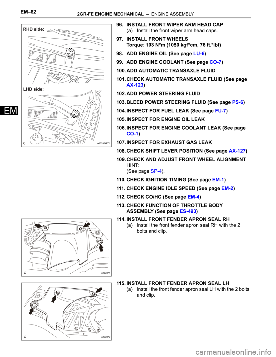
96. INSTALL FRONT WIPER ARM HEAD CAP
(a) Install the front wiper arm head caps.
97. INSTALL FRONT WHEELS
Torque: 103 N*m (1050 kgf*cm, 76 ft.*lbf)
98. ADD ENGINE OIL (See page LU-6)
99. ADD ENGINE COOLANT (See page CO-7)
100. ADD AUTOMATIC TRANSAXLE FLUID
101. CHECK AUTOMATIC TRANSAXLE FLUID (See page
AX-123)
102. ADD POWER STEERING FLUID
103. BLEED POWER STEERING FLUID (See page PS-6)
104. INSPECT FOR FUEL LEAK (See page FU-7)
105. INSPECT FOR ENGINE OIL LEAK
106. INSPECT FOR ENGINE COOLANT LEAK (See page
CO-1)
107. INSPECT FOR EXHAUST GAS LEAK
108. CHECK SHIFT LEVER POSITION (See page AX-127)
109. CHECK AND ADJUST FRONT WHEEL ALIGNMENT
HINT:
(See page SP-4).
110. CHECK IGNITION TIMING (See page EM-1)
111. CHECK ENGINE IDLE SPEED (See page EM-2)
112. CHECK CO/HC (See page EM-4)
113. CHECK FUNCTION OF THROTTLE BODY
ASSEMBLY (See page ES-493)
114. INSTALL FRONT FENDER APRON SEAL RH
(a) Install the front fender apron seal RH with the 2
bolts and clip.
115. INSTALL FRONT FENDER APRON SEAL LH
(a) Install the front fender apron seal LH with the 2 bolts
and clip.
A165364E01
A162371
A162370