2007 TOYOTA SIENNA coolant
[x] Cancel search: coolantPage 369 of 3000

2GR-FE ENGINE CONTROL SYSTEM – SFI SYSTEMES–51
ES
FAIL-SAFE CHART
If any of the following DTCs are set, the ECM enters fail-safe
mode to allow the vehicle to be driven temporarily.
HINT:
• *1: The vehicle can be driven slowly when the accelerator
pedal is depressed firmly and slowly. If the accelerator
pedal is depressed quickly, the vehicle may speed up and
slow down erratically.
• *2: Misfire related fail-safe operations occur when catalyst
overheat malfunctions occur.
DTCs Components Fail-Safe OperationsFail-Safe Deactivation
Conditions
P0031, P0032, P0051 and P0052Air-Fuel Ratio (A/F) Sensor
HeaterECM turns off A/F sensor heater Ignition switch off
P0037, P0038, P0057 and P0058Heated Oxygen (HO2) Sensor
HeaterECM turns off HO2 sensor heater Ignition switch off
P0100, P0102 and P0103 Mass Air Flow (MAF) MeterECM calculates ignition timing
according to engine speed and
throttle valve positionPass condition detected
P0110, P0112 and P0113Intake Air Temperature (IAT)
SensorECM estimates IAT to be 20
C
(68
F)Pass condition detected
P0115, P0117 and P0118Engine Coolant Temperature
(ECT) SensorECM estimates ECT to be 80
C
(176
F)Pass condition detected
P0120, P0121, P0122, P0123,
P0220, P0222, P0223, P0604,
P0606, P0607, P0657, P2102,
P2103, P2111, P2112, P2118,
P2119 and P2135Electronic Throttle Control
System (ETCS)ECM cuts off throttle actuator
current and throttle valve returned
to 6.5
throttle position by return
spring
ECM then adjusts engine output
by controlling fuel injection
(intermittent fuel-cut) and ignition
timing in accordance with
accelerator pedal opening angle,
to allow vehicle to continue at
minimal speed*1Pass condition detected and then
ignition switch turned off
P0300, P0301, P0302, P0303,
P0304, P0305 and P0306*2• Fuel injector
• Electronic Throttle Control
System (ETCS)When misfire occurs, fuel cut is
performed for catalyst overheat
malfunction prevention
• During normal load and
normal engine speed (MIL is
blinking)
- Fuel cut is performed on
malfunctioning cylinder
• During high load and high
engine speed (MIL is
blinking)
- Throttle valve opening angle
control is performed
- All cylinder fuel cut or
malfunction cylinder fuel cutPass condition detected and then
ignition switch turned OFF
P0327, P0328, P0332 and P0333 Knock SensorECM sets ignition timing to
maximum retardIgnition switch off
P0351 to P0356 Igniter ECM cuts fuel Pass condition detected
P2120, P2121, P2122, P2123,
P2125, P2127, P2128 and P2138Accelerator Pedal Position (APP)
SensorAPP sensor has 2 sensor circuits:
Main and Sub
If either of circuits malfunctions,
ECM controls engine using the
other circuit
If both of circuits malfunction,
ECM regards accelerator pedal
as being released. As a result,
throttle valve is closed and engine
idlesPass condition detected and then
ignition switch turned off
Page 373 of 3000
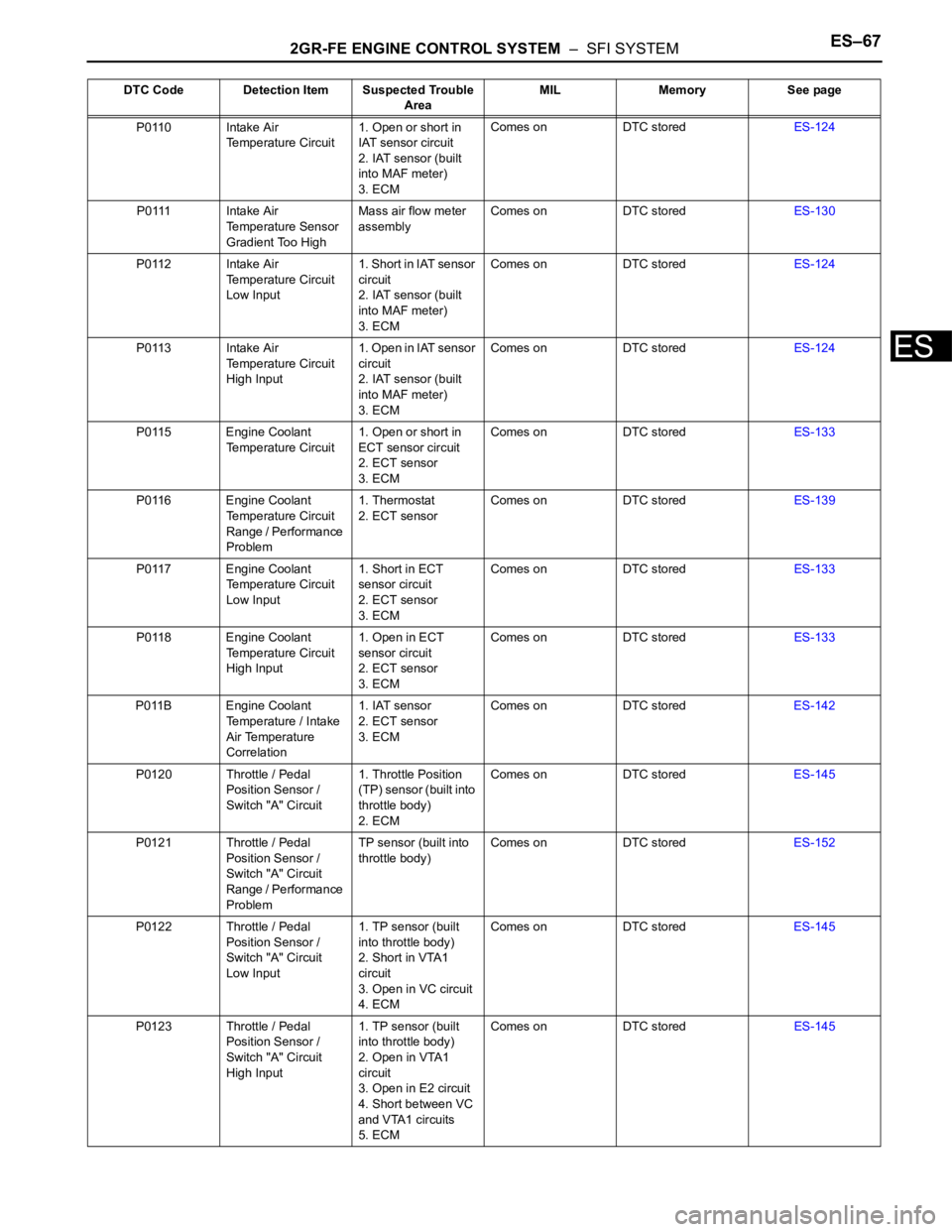
2GR-FE ENGINE CONTROL SYSTEM – SFI SYSTEMES–67
ES
P0110 Intake Air
Temperature Circuit1. Open or short in
IAT sensor circuit
2. IAT sensor (built
into MAF meter)
3. ECMComes on DTC storedES-124
P0111 Intake Air
Temperature Sensor
Gradient Too HighMass air flow meter
assemblyComes on DTC storedES-130
P0112 Intake Air
Temperature Circuit
Low Input1. Short in IAT sensor
circuit
2. IAT sensor (built
into MAF meter)
3. ECMComes on DTC storedES-124
P0113 Intake Air
Temperature Circuit
High Input1 . O p e n i n I AT s e n s o r
circuit
2. IAT sensor (built
into MAF meter)
3. ECMComes on DTC storedES-124
P0115 Engine Coolant
Temperature Circuit1. Open or short in
ECT sensor circuit
2. ECT sensor
3. ECMComes on DTC storedES-133
P0116 Engine Coolant
Temperature Circuit
Range / Performance
Problem1. Thermostat
2. ECT sensorComes on DTC storedES-139
P0117 Engine Coolant
Temperature Circuit
Low Input1. Short in ECT
sensor circuit
2. ECT sensor
3. ECMComes on DTC storedES-133
P0118 Engine Coolant
Temperature Circuit
High Input1. Open in ECT
sensor circuit
2. ECT sensor
3. ECMComes on DTC storedES-133
P011B Engine Coolant
Temperature / Intake
Air Temperature
Correlation1. IAT sensor
2. ECT sensor
3. ECMComes on DTC storedES-142
P0120 Throttle / Pedal
Position Sensor /
Switch "A" Circuit1. Throttle Position
(TP) sensor (built into
throttle body)
2. ECMComes on DTC storedES-145
P0121 Throttle / Pedal
Position Sensor /
Switch "A" Circuit
Range / Performance
ProblemTP sensor (built into
throttle body)Comes on DTC storedES-152
P0122 Throttle / Pedal
Position Sensor /
Switch "A" Circuit
Low Input1. TP sensor (built
into throttle body)
2. Short in VTA1
circuit
3. Open in VC circuit
4. ECMComes on DTC storedES-145
P0123 Throttle / Pedal
Position Sensor /
Switch "A" Circuit
High Input1. TP sensor (built
into throttle body)
2. Open in VTA1
circuit
3. Open in E2 circuit
4. Short between VC
and VTA1 circuits
5. ECMComes on DTC storedES-145 DTC Code Detection Item Suspected Trouble
AreaMIL Memory See page
Page 374 of 3000
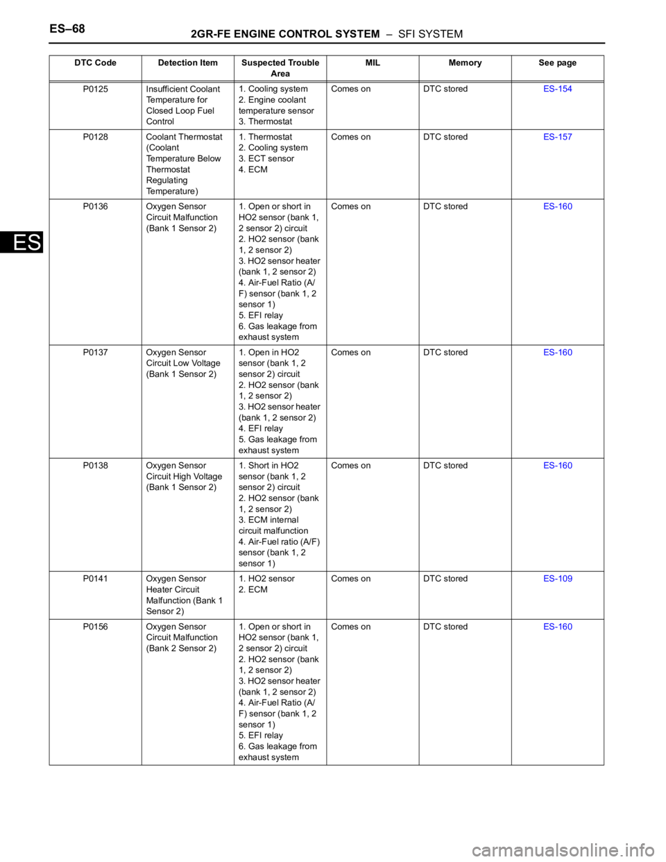
ES–682GR-FE ENGINE CONTROL SYSTEM – SFI SYSTEM
ES
P0125 Insufficient Coolant
Temperature for
Closed Loop Fuel
Control1. Cooling system
2. Engine coolant
temperature sensor
3. ThermostatComes on DTC storedES-154
P0128 Coolant Thermostat
(Coolant
Temperature Below
Thermostat
Regulating
Temperature)1. Thermostat
2. Cooling system
3. ECT sensor
4. ECMComes on DTC storedES-157
P0136 Oxygen Sensor
Circuit Malfunction
(Bank 1 Sensor 2)1. Open or short in
HO2 sensor (bank 1,
2 sensor 2) circuit
2. HO2 sensor (bank
1, 2 sensor 2)
3. HO2 sensor heater
(bank 1, 2 sensor 2)
4. Air-Fuel Ratio (A/
F) sensor (bank 1, 2
sensor 1)
5. EFI relay
6. Gas leakage from
exhaust systemComes on DTC storedES-160
P0137 Oxygen Sensor
Circuit Low Voltage
(Bank 1 Sensor 2)1. Open in HO2
sensor (bank 1, 2
sensor 2) circuit
2. HO2 sensor (bank
1, 2 sensor 2)
3. HO2 sensor heater
(bank 1, 2 sensor 2)
4. EFI relay
5. Gas leakage from
exhaust systemComes on DTC storedES-160
P0138 Oxygen Sensor
Circuit High Voltage
(Bank 1 Sensor 2)1. Short in HO2
sensor (bank 1, 2
sensor 2) circuit
2. HO2 sensor (bank
1, 2 sensor 2)
3. ECM internal
circuit malfunction
4. Air-Fuel ratio (A/F)
sensor (bank 1, 2
sensor 1)Comes on DTC storedES-160
P0141 Oxygen Sensor
Heater Circuit
Malfunction (Bank 1
Sensor 2)1. HO2 sensor
2. ECMComes on DTC storedES-109
P0156 Oxygen Sensor
Circuit Malfunction
(Bank 2 Sensor 2)1. Open or short in
HO2 sensor (bank 1,
2 sensor 2) circuit
2. HO2 sensor (bank
1, 2 sensor 2)
3. HO2 sensor heater
(bank 1, 2 sensor 2)
4. Air-Fuel Ratio (A/
F) sensor (bank 1, 2
sensor 1)
5. EFI relay
6. Gas leakage from
exhaust systemComes on DTC storedES-160 DTC Code Detection Item Suspected Trouble
AreaMIL Memory See page
Page 375 of 3000
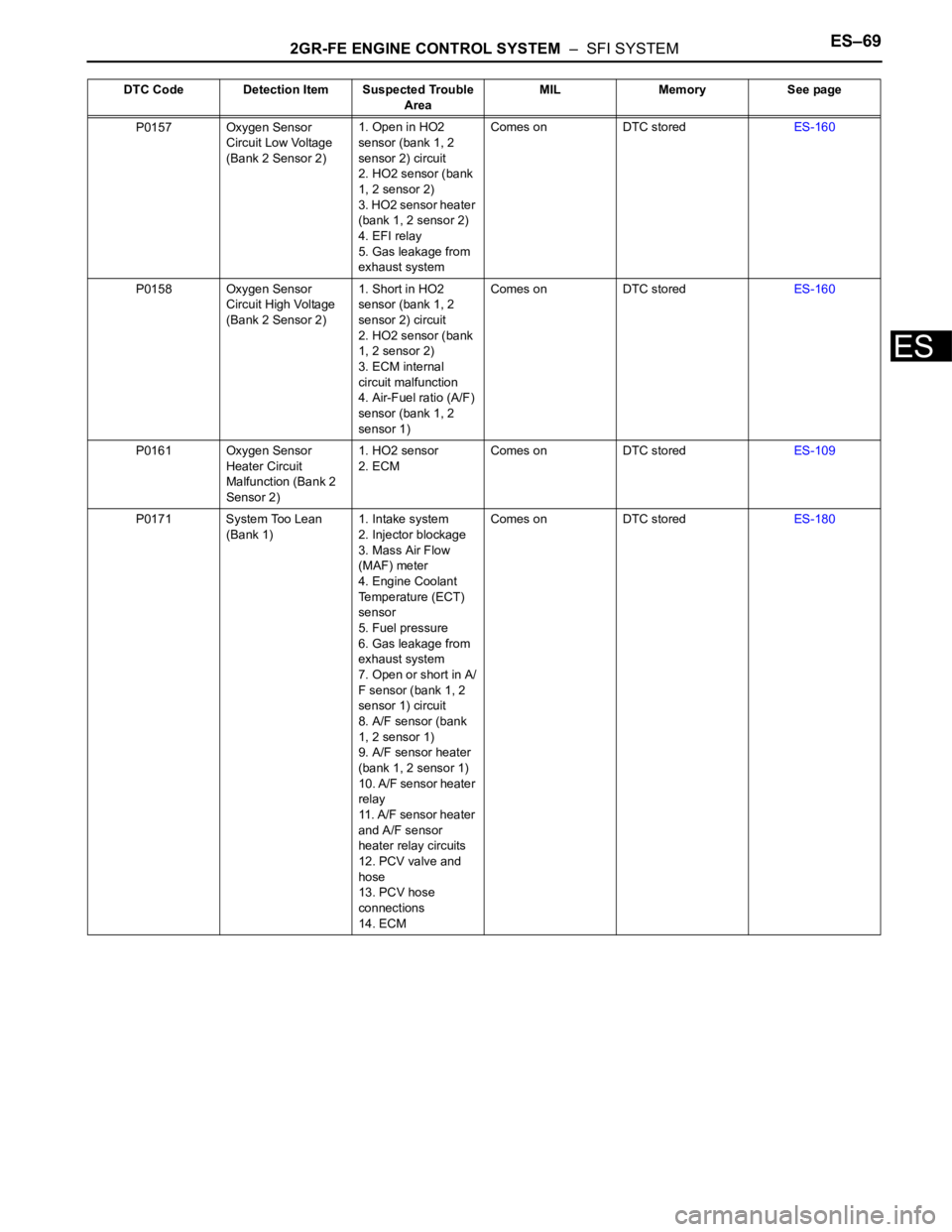
2GR-FE ENGINE CONTROL SYSTEM – SFI SYSTEMES–69
ES
P0157 Oxygen Sensor
Circuit Low Voltage
(Bank 2 Sensor 2)1. Open in HO2
sensor (bank 1, 2
sensor 2) circuit
2. HO2 sensor (bank
1, 2 sensor 2)
3. HO2 sensor heater
(bank 1, 2 sensor 2)
4. EFI relay
5. Gas leakage from
exhaust systemComes on DTC storedES-160
P0158 Oxygen Sensor
Circuit High Voltage
(Bank 2 Sensor 2)1. Short in HO2
sensor (bank 1, 2
sensor 2) circuit
2. HO2 sensor (bank
1, 2 sensor 2)
3. ECM internal
circuit malfunction
4. Air-Fuel ratio (A/F)
sensor (bank 1, 2
sensor 1)Comes on DTC storedES-160
P0161 Oxygen Sensor
Heater Circuit
Malfunction (Bank 2
Sensor 2)1. HO2 sensor
2. ECMComes on DTC storedES-109
P0171 System Too Lean
(Bank 1)1. Intake system
2. Injector blockage
3. Mass Air Flow
(MAF) meter
4. Engine Coolant
Temperature (ECT)
sensor
5. Fuel pressure
6. Gas leakage from
exhaust system
7. Open or short in A/
F sensor (bank 1, 2
sensor 1) circuit
8. A/F sensor (bank
1, 2 sensor 1)
9. A/F sensor heater
(bank 1, 2 sensor 1)
10. A/F sensor heater
relay
11. A/F sensor heater
and A/F sensor
heater relay circuits
12. PCV valve and
hose
13. PCV hose
connections
14. ECMComes on DTC storedES-180 DTC Code Detection Item Suspected Trouble
AreaMIL Memory See page
Page 376 of 3000

ES–702GR-FE ENGINE CONTROL SYSTEM – SFI SYSTEM
ES
P0172 System Too Rich
(Bank 1)1. Injector leakage or
blockage
2. MAF meter
3. ECT sensor
4. Ignition system
5. Fuel pressure
6. Gas leakage from
exhaust system
7. Open or short in A/
F sensor (bank 1, 2
sensor 1) circuit
8. A/F sensor (bank
1, 2 sensor 1)
9. A/F sensor heater
(bank 1, 2 sensor 1)
10. A/F sensor heater
relay
11. A/F sensor heater
and A/F sensor
heater relay circuits
12. ECMComes on DTC storedES-180
P0174 System Too Lean
(Bank 2)1. Intake system
2. Injector blockage
3. Mass Air Flow
(MAF) meter
4. Engine Coolant
Temperature (ECT)
sensor
5. Fuel pressure
6. Gas leakage from
exhaust system
7. Open or short in A/
F sensor (bank 1, 2
sensor 1) circuit
8. A/F sensor (bank
1, 2 sensor 1)
9. A/F sensor heater
(bank 1, 2 sensor 1)
10. A/F sensor heater
relay
11. A/F sensor heater
and A/F sensor
heater relay circuits
12. PCV valve and
hose
13. PCV hose
connections
14. ECMComes on DTC storedES-180 DTC Code Detection Item Suspected Trouble
AreaMIL Memory See page
Page 378 of 3000
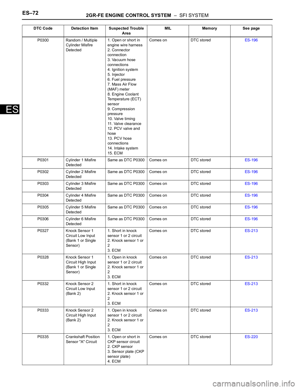
ES–722GR-FE ENGINE CONTROL SYSTEM – SFI SYSTEM
ES
P0300 Random / Multiple
Cylinder Misfire
Detected1. Open or short in
engine wire harness
2. Connector
connection
3. Vacuum hose
connections
4. Ignition system
5. Injector
6. Fuel pressure
7. Mass Air Flow
(MAF) meter
8. Engine Coolant
Temperature (ECT)
sensor
9. Compression
pressure
10. Valve timing
11. Valve clearance
12. PCV valve and
hose
13. PCV hose
connections
14. Intake system
15. ECMComes on DTC storedES-196
P0301 Cylinder 1 Misfire
DetectedSame as DTC P0300 Comes on DTC storedES-196
P0302 Cylinder 2 Misfire
DetectedSame as DTC P0300 Comes on DTC storedES-196
P0303 Cylinder 3 Misfire
DetectedSame as DTC P0300 Comes on DTC storedES-196
P0304 Cylinder 4 Misfire
DetectedSame as DTC P0300 Comes on DTC storedES-196
P0305 Cylinder 5 Misfire
DetectedSame as DTC P0300 Comes on DTC storedES-196
P0306 Cylinder 6 Misfire
DetectedSame as DTC P0300 Comes on DTC storedES-196
P0327 Knock Sensor 1
Circuit Low Input
(Bank 1 or Single
Sensor)1. Short in knock
sensor 1 or 2 circuit
2. Knock sensor 1 or
2
3. ECMComes on DTC storedES-213
P0328 Knock Sensor 1
Circuit High Input
(Bank 1 or Single
Sensor)1. Open in knock
sensor 1 or 2 circuit
2. Knock sensor 1 or
2
3. ECMComes on DTC storedES-213
P0332 Knock Sensor 2
Circuit Low Input
(Bank 2)1. Short in knock
sensor 1 or 2 circuit
2. Knock sensor 1 or
2
3. ECMComes on DTC storedES-213
P0333 Knock Sensor 2
Circuit High Input
(Bank 2)1. Open in knock
sensor 1 or 2 circuit
2. Knock sensor 1 or
2
3. ECMComes on DTC storedES-213
P0335 Crankshaft Position
Sensor "A" Circuit1. Open or short in
CKP sensor circuit
2. CKP sensor
3. Sensor plate (CKP
sensor plate)
4. ECMComes on DTC storedES-220 DTC Code Detection Item Suspected Trouble
AreaMIL Memory See page
Page 389 of 3000
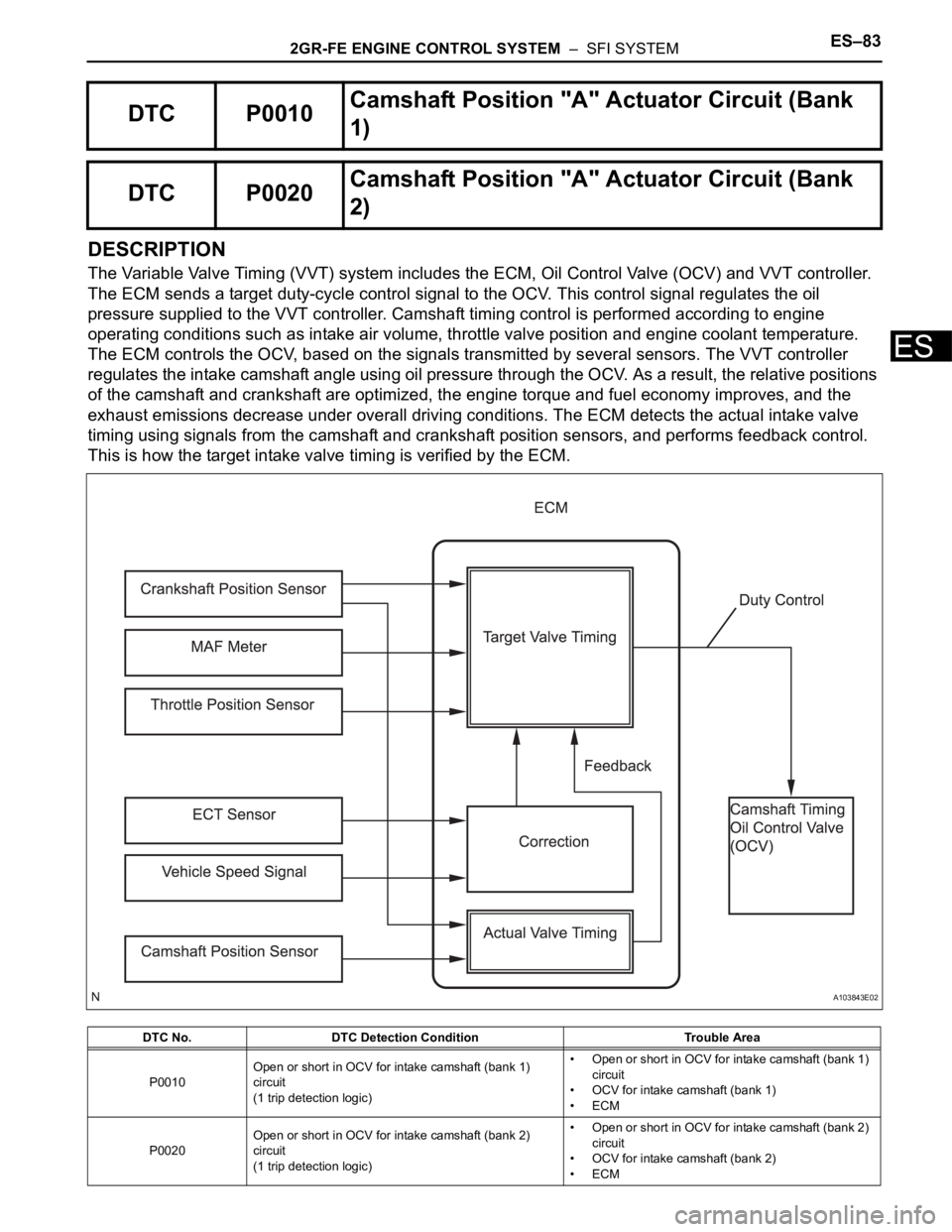
2GR-FE ENGINE CONTROL SYSTEM – SFI SYSTEMES–83
ES
DESCRIPTION
The Variable Valve Timing (VVT) system includes the ECM, Oil Control Valve (OCV) and VVT controller.
The ECM sends a target duty-cycle control signal to the OCV. This control signal regulates the oil
pressure supplied to the VVT controller. Camshaft timing control is performed according to engine
operating conditions such as intake air volume, throttle valve position and engine coolant temperature.
The ECM controls the OCV, based on the signals transmitted by several sensors. The VVT controller
regulates the intake camshaft angle using oil pressure through the OCV. As a result, the relative positions
of the camshaft and crankshaft are optimized, the engine torque and fuel economy improves, and the
exhaust emissions decrease under overall driving conditions. The ECM detects the actual intake valve
timing using signals from the camshaft and crankshaft position sensors, and performs feedback control.
This is how the target intake valve timing is verified by the ECM.
DTC P0010Camshaft Position "A" Actuator Circuit (Bank
1)
DTC P0020Camshaft Position "A" Actuator Circuit (Bank
2)
DTC No. DTC Detection Condition Trouble Area
P0010Open or short in OCV for intake camshaft (bank 1)
circuit
(1 trip detection logic)• Open or short in OCV for intake camshaft (bank 1)
circuit
• OCV for intake camshaft (bank 1)
•ECM
P0020Open or short in OCV for intake camshaft (bank 2)
circuit
(1 trip detection logic)• Open or short in OCV for intake camshaft (bank 2)
circuit
• OCV for intake camshaft (bank 2)
•ECM
A103843E02
Page 395 of 3000

2GR-FE ENGINE CONTROL SYSTEM – SFI SYSTEMES–89
ES
3) After above conditions 1) and 2) are met, the OCV is forcibly activated 63 times or more.
DTCs P0011 and P0021 (Advanced Cam Timing) are detected with 1 trip detection logic.
DTCs P0012 and P0022 (Retarded Cam Timing) are detected with 2 trip detection logic.
These DTCs indicate that the VVT controller cannot operate properly due to OCV malfunctions or the
presence of foreign objects in the OCV.
The monitor will not run unless the following conditions are met:
- The engine is warm (the engine coolant temperature is 75
C [167F] or more).
- The vehicle has been driven at more than 40 mph (64 km/h) for 3 minutes.
- The engine has idled for 3 minutes.
MONITOR STRATEGY
TYPICAL ENABLING CONDITIONS
TYPICAL MALFUNCTION THRESHOLDS
P0011, P0021:
P0012, P0022:
If the difference between the target and actual camshaft timings is greater than the specified value, the
ECM operates the VVT actuator.
Then, the ECM monitors the camshaft timing change for 5 seconds.
WIRING DIAGRAM
Refer to DTC P0010 (See page ES-77).
INSPECTION PROCEDURE
Related DTCsP0011: Advanced intake camshaft timing (bank 1)
P0012: Retarded intake camshaft timing (bank 1)
P0021: Advanced intake camshaft timing (bank 2)
P0022: Retarded intake camshaft timing (bank 2)
Required sensors / components (Main) VVT OCV, VVT Actuator
Required sensors / components (Related) Crankshaft position sensor, Camshaft position sensor, ECT sensor
Frequency of operation Once per driving cycles
Duration Less than 10 seconds
MIL operationP0011 and P0021: Immediate
P0012 and P0022: 2 driving cycles
Sequence operation None
The monitor will run whenever these DTCs are not
presentP0100, P0101, P0102, P0103 (MAF Sensor), P0115, P0116, P0117, P0118 (ECT
Sensor), P0125 (Insufficient ECT for Closed Loop), P0335 (CKP Sensor), P0340
(CMP Sensor), P0351, P0352, P0353, P0354, P0355, P0356 (Ignitor)
Battery voltage 11 V or more
Engine RPM 500 to 4000 rpm
ECT 75 to 100
C (167 to 212F)
Duration of actual valve timing and target valve timing More than 5
CA (Crankshaft angle)
Valve timing No change in advanced valve timing
Duration of actual valve timing and target valve timing More than 5
CA (Crankshaft angle)
Valve timing No change in retarded valve timing
Abnormal bankAdvanced timing over
(Valve timing is out of specified range)Retarded timing over
(Valve timing is out of specified range)
Bank 1 P0011 P0012
Bank 2 P0021 P0022