Page 727 of 3000
2GR-FE ENGINE CONTROL SYSTEM – SFI SYSTEMES–441
ES
(c) Pressurize the EVAP system by 3.2 to 3.7 kPa (24 to 28
mmHg).
(d) Apply soapy water to the piping and the connecting parts
of the EVAP system.
(e) Look for areas where bubbles appear. This indicates a
leak point.
(f) Repair or replace the leak point.
NEXT
(a) Replace the charcoal canister assembly (See page EC-
8).
NOTICE:
When replacing the canister, check the canister
pump module interior and related pipes for water,
fuel and other liquids. If liquids are present, check
for disconnections and/or cracks in the following: 1)
the pipe from the air inlet port to the canister pump
module; 2) the canister filter; 3) the fuel tank vent
hose.
A137044E01
Go to step 37
30REPLACE CHARCOAL CANISTER ASSEMBLY
Page 777 of 3000
2GR-FE ENGINE CONTROL SYSTEM – SFI SYSTEMES–15
ES
BASIC INSPECTION
When a malfunction is not confirmed by the DTC check,
troubleshooting should be carried out in all circuits
considered to be possible causes of the problem. In many
cases, by carrying out the basic engine check shown in the
following flowchart, the location of the problem can be found
quickly and efficiently. Therefore, using this check is essential
when engine troubleshooting.
NOTICE:
Carry out this check with the engine stopped and ignition
switch off.
Result
NG
OK
NG
OK
NG
OK
(a) Visually check that the air filter is not excessively
contaminated with dirt or oil.
NG
OK
(a) Check the idling speed (See page EM-2).
1CHECK BATTERY VOLTAGE
Result Proceed to
11 V or more OK
Below 11 V NG
CHARGE OR REPLACE BATTERY
2CHECK WHETHER ENGINE CRANKS
PROCEED TO PROBLEM SYMPTOMS
TA B L E
3CHECK WHETHER ENGINE STARTS
GO TO STEP 6
4CHECK AIR FILTER
REPLACE AIR FILTER
5CHECK IDLING SPEED
Page 876 of 3000

2GR-FE ENGINE MECHANICAL – ENGINE ASSEMBLYEM–59
EM
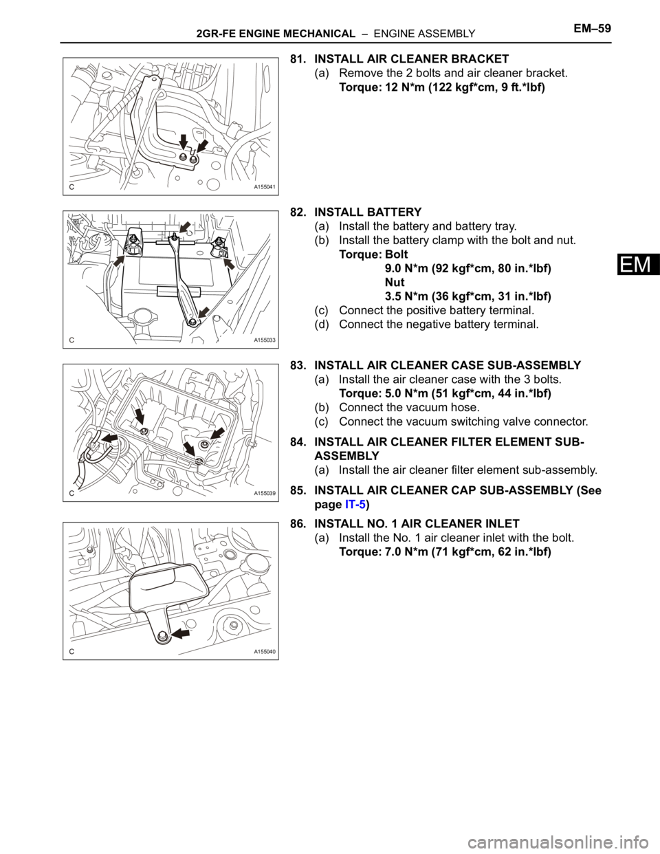
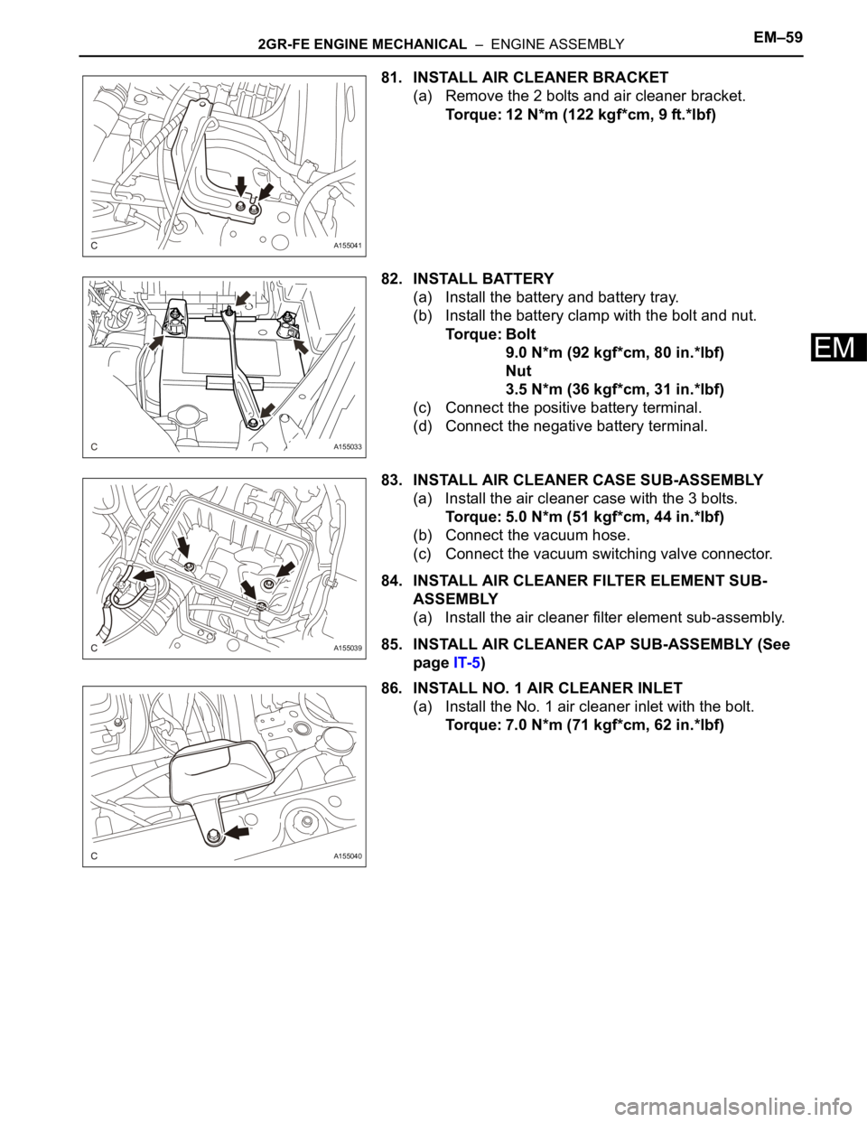
81. INSTALL AIR CLEANER BRACKET
(a) Remove the 2 bolts and air cleaner bracket.
Torque: 12 N*m (122 kgf*cm, 9 ft.*lbf)
82. INSTALL BATTERY
(a) Install the battery and battery tray.
(b) Install the battery clamp with the bolt and nut.
Torque: Bolt
9.0 N*m (92 kgf*cm, 80 in.*lbf)
Nut
3.5 N*m (36 kgf*cm, 31 in.*lbf)
(c) Connect the positive battery terminal.
(d) Connect the negative battery terminal.
83. INSTALL AIR CLEANER CASE SUB-ASSEMBLY
(a) Install the air cleaner case with the 3 bolts.
Torque: 5.0 N*m (51 kgf*cm, 44 in.*lbf)
(b) Connect the vacuum hose.
(c) Connect the vacuum switching valve connector.
84. INSTALL AIR CLEANER FILTER ELEMENT SUB-
ASSEMBLY
(a) Install the air cleaner filter element sub-assembly.
85. INSTALL AIR CLEANER CAP SUB-ASSEMBLY (See
page IT-5)
86. INSTALL NO. 1 AIR CLEANER INLET
(a) Install the No. 1 air cleaner inlet with the bolt.
Torque: 7.0 N*m (71 kgf*cm, 62 in.*lbf)
A155041
A155033
A155039
A155040
Page 931 of 3000

2GR-FE ENGINE MECHANICAL – ENGINEEM–1
EM
ENGINE
ON-VEHICLE INSPECTION
1. INSPECT ENGINE COOLANT
(a) Inspect the engine coolant (See page CO-1).
2. INSPECT ENGINE OIL
(a) Inspect the engine oil (See page LU-1).
3. INSPECT BATTERY
(a) Inspect the battery (See page CH-5).
4. INSPECT AIR CLEANER FILTER ELEMENT SUB-
ASSEMBLY
(a) Remove the air cleaner filter element sub-assembly.
(b) Visually check that there is no dirt, blockage, and/or
damage to the air cleaner filter element.
HINT:
• If there is any dirt or a blockage in the air cleaner
filter element, clean it with compressed air.
• If any dirt or a blockage remains even after
cleaning the air cleaner filter element with
compressed air, replace it.
5. INSPECT SPARK PLUG
(a) Inspect the spark plugs (See page IG-5).
6. INSPECT VALVE LASH ADJUSTER NOISE
(a) Rev up the engine several times. Check that the
engine does not emit unusual noises.
If unusual noises occur, warm up the engine and
idle it for over 30 minutes. Then repeat this
procedure.
HINT:
If any defects or problems are found during the
inspection above, perform lash adjuster inspection
(See page EM-100).
7. INSPECT IGNITION TIMING
(a) Warm up the engine.
(b) When using the intelligent tester:
Check the ignition timing.
(1) Connect the intelligent tester to the DLC3.
(2) Enter DATA LIST mode with the intelligent
tester.
Ignition timing:
8 to 12
BTDC at idle
HINT:
Refer to the intelligent tester operator's manual
for help when selecting the DATA LIST.
C110200E02
Page 934 of 3000

EM–42GR-FE ENGINE MECHANICAL – ENGINE
EM
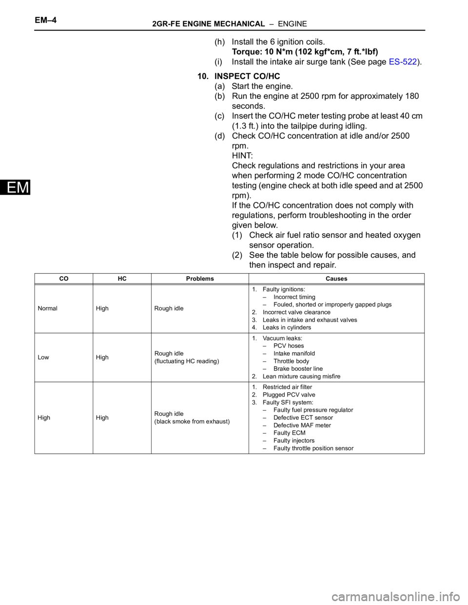
(h) Install the 6 ignition coils.
Torque: 10 N*m (102 kgf*cm, 7 ft.*lbf)
(i) Install the intake air surge tank (See page ES-522).
10. INSPECT CO/HC
(a) Start the engine.
(b) Run the engine at 2500 rpm for approximately 180
seconds.
(c) Insert the CO/HC meter testing probe at least 40 cm
(1.3 ft.) into the tailpipe during idling.
(d) Check CO/HC concentration at idle and/or 2500
rpm.
HINT:
Check regulations and restrictions in your area
when performing 2 mode CO/HC concentration
testing (engine check at both idle speed and at 2500
rpm).
If the CO/HC concentration does not comply with
regulations, perform troubleshooting in the order
given below.
(1) Check air fuel ratio sensor and heated oxygen
sensor operation.
(2) See the table below for possible causes, and
then inspect and repair.
CO HC Problems Causes
Normal High Rough idle1. Faulty ignitions:
– Incorrect timing
– Fouled, shorted or improperly gapped plugs
2. Incorrect valve clearance
3. Leaks in intake and exhaust valves
4. Leaks in cylinders
Low HighRough idle
(fluctuating HC reading)1. Vacuum leaks:
– PCV hoses
– Intake manifold
– Throttle body
– Brake booster line
2. Lean mixture causing misfire
High HighRough idle
(black smoke from exhaust)1. Restricted air filter
2. Plugged PCV valve
3. Faulty SFI system:
– Faulty fuel pressure regulator
– Defective ECT sensor
– Defective MAF meter
–Faulty ECM
– Faulty injectors
– Faulty throttle position sensor
Page 987 of 3000

EM–282GR-FE ENGINE MECHANICAL – ENGINE ASSEMBLY
EM
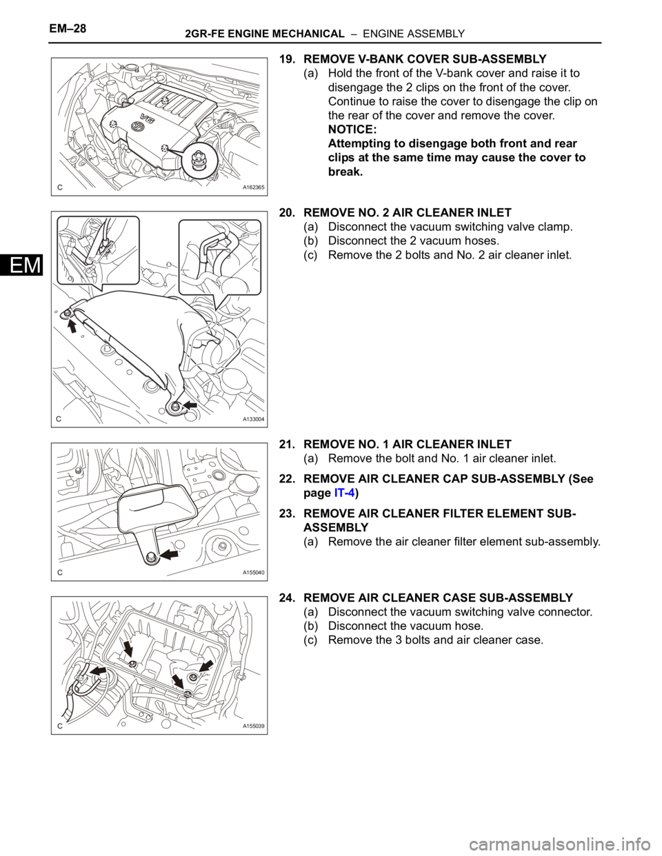
19. REMOVE V-BANK COVER SUB-ASSEMBLY
(a) Hold the front of the V-bank cover and raise it to
disengage the 2 clips on the front of the cover.
Continue to raise the cover to disengage the clip on
the rear of the cover and remove the cover.
NOTICE:
Attempting to disengage both front and rear
clips at the same time may cause the cover to
break.
20. REMOVE NO. 2 AIR CLEANER INLET
(a) Disconnect the vacuum switching valve clamp.
(b) Disconnect the 2 vacuum hoses.
(c) Remove the 2 bolts and No. 2 air cleaner inlet.
21. REMOVE NO. 1 AIR CLEANER INLET
(a) Remove the bolt and No. 1 air cleaner inlet.
22. REMOVE AIR CLEANER CAP SUB-ASSEMBLY (See
page IT-4)
23. REMOVE AIR CLEANER FILTER ELEMENT SUB-
ASSEMBLY
(a) Remove the air cleaner filter element sub-assembly.
24. REMOVE AIR CLEANER CASE SUB-ASSEMBLY
(a) Disconnect the vacuum switching valve connector.
(b) Disconnect the vacuum hose.
(c) Remove the 3 bolts and air cleaner case.
A162365
A133004
A155040
A155039
Page 1018 of 3000

2GR-FE ENGINE MECHANICAL – ENGINE ASSEMBLYEM–59
EM
81. INSTALL AIR CLEANER BRACKET
(a) Remove the 2 bolts and air cleaner bracket.
Torque: 12 N*m (122 kgf*cm, 9 ft.*lbf)
82. INSTALL BATTERY
(a) Install the battery and battery tray.
(b) Install the battery clamp with the bolt and nut.
Torque: Bolt
9.0 N*m (92 kgf*cm, 80 in.*lbf)
Nut
3.5 N*m (36 kgf*cm, 31 in.*lbf)
(c) Connect the positive battery terminal.
(d) Connect the negative battery terminal.
83. INSTALL AIR CLEANER CASE SUB-ASSEMBLY
(a) Install the air cleaner case with the 3 bolts.
Torque: 5.0 N*m (51 kgf*cm, 44 in.*lbf)
(b) Connect the vacuum hose.
(c) Connect the vacuum switching valve connector.
84. INSTALL AIR CLEANER FILTER ELEMENT SUB-
ASSEMBLY
(a) Install the air cleaner filter element sub-assembly.
85. INSTALL AIR CLEANER CAP SUB-ASSEMBLY (See
page IT-5)
86. INSTALL NO. 1 AIR CLEANER INLET
(a) Install the No. 1 air cleaner inlet with the bolt.
Torque: 7.0 N*m (71 kgf*cm, 62 in.*lbf)
A155041
A155033
A155039
A155040
Page 1214 of 3000
2GR-FE INTAKE – INTAKE AIR CONTROL VALVEIT–5
IT
REMOVAL
1. REMOVE NO. 2 AIR CLEANER INLET (See page EM-
28)
2. REMOVE AIR CLEANER CAP SUB-ASSEMBLY
(a) Disconnect the 3 vacuum hoses.
(b) Loosen the bolt, disconnect the 2 connectors, and
remove the 2 vacuum hoses.
(c) Remove the 2 bolts, air cleaner cap sub-assembly,
and air cleaner filter element.
3. REMOVE NO. 3 INTAKE AIR CONTROL VALVE
ASSEMBLY
(a) Disengage the 2 claws and remove the No. 3 intake
air control valve assembly.
A162723E01
A162726
A161845
A162725