Page 196 of 3000

PS–14POWER STEERING – VANE PUMP
PS
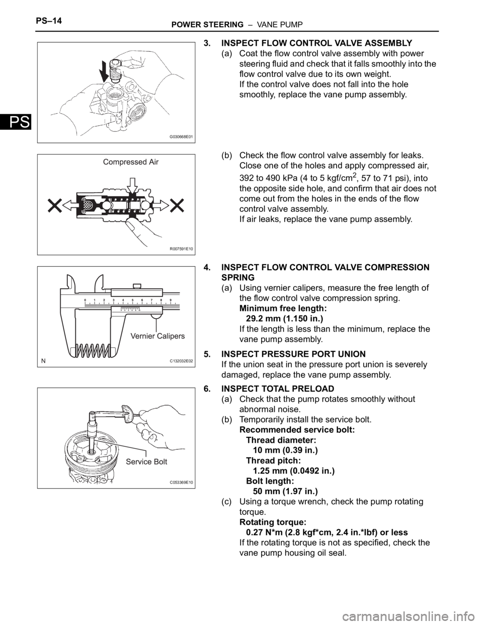
3. INSPECT FLOW CONTROL VALVE ASSEMBLY
(a) Coat the flow control valve assembly with power
steering fluid and check that it falls smoothly into the
flow control valve due to its own weight.
If the control valve does not fall into the hole
smoothly, replace the vane pump assembly.
(b) Check the flow control valve assembly for leaks.
Close one of the holes and apply compressed air,
392 to 490 kPa (4 to 5 kgf/cm
2, 57 to 71 psi), into
the opposite side hole, and confirm that air does not
come out from the holes in the ends of the flow
control valve assembly.
If air leaks, replace the vane pump assembly.
4. INSPECT FLOW CONTROL VALVE COMPRESSION
SPRING
(a) Using vernier calipers, measure the free length of
the flow control valve compression spring.
Minimum free length:
29.2 mm (1.150 in.)
If the length is less than the minimum, replace the
vane pump assembly.
5. INSPECT PRESSURE PORT UNION
If the union seat in the pressure port union is severely
damaged, replace the vane pump assembly.
6. INSPECT TOTAL PRELOAD
(a) Check that the pump rotates smoothly without
abnormal noise.
(b) Temporarily install the service bolt.
Recommended service bolt:
Thread diameter:
10 mm (0.39 in.)
Thread pitch:
1.25 mm (0.0492 in.)
Bolt length:
50 mm (1.97 in.)
(c) Using a torque wrench, check the pump rotating
torque.
Rotating torque:
0.27 N*m (2.8 kgf*cm, 2.4 in.*lbf) or less
If the rotating torque is not as specified, check the
vane pump housing oil seal.
G030668E01
R007591E10
C132032E02
C053369E10
Page 341 of 3000
2GR-FE ENGINE CONTROL SYSTEM – SFI SYSTEMES–15
ES
BASIC INSPECTION
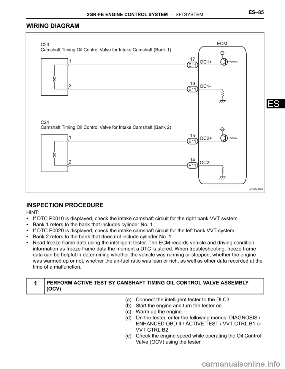
When a malfunction is not confirmed by the DTC check,
troubleshooting should be carried out in all circuits
considered to be possible causes of the problem. In many
cases, by carrying out the basic engine check shown in the
following flowchart, the location of the problem can be found
quickly and efficiently. Therefore, using this check is essential
when engine troubleshooting.
NOTICE:
Carry out this check with the engine stopped and ignition
switch off.
Result
NG
OK
NG
OK
NG
OK
(a) Visually check that the air filter is not excessively
contaminated with dirt or oil.
NG
OK
(a) Check the idling speed (See page EM-2).
1CHECK BATTERY VOLTAGE
Result Proceed to
11 V or more OK
Below 11 V NG
CHARGE OR REPLACE BATTERY
2CHECK WHETHER ENGINE CRANKS
PROCEED TO PROBLEM SYMPTOMS
TA B L E
3CHECK WHETHER ENGINE STARTS
GO TO STEP 6
4CHECK AIR FILTER
REPLACE AIR FILTER
5CHECK IDLING SPEED
Page 391 of 3000

2GR-FE ENGINE CONTROL SYSTEM – SFI SYSTEMES–85
ES
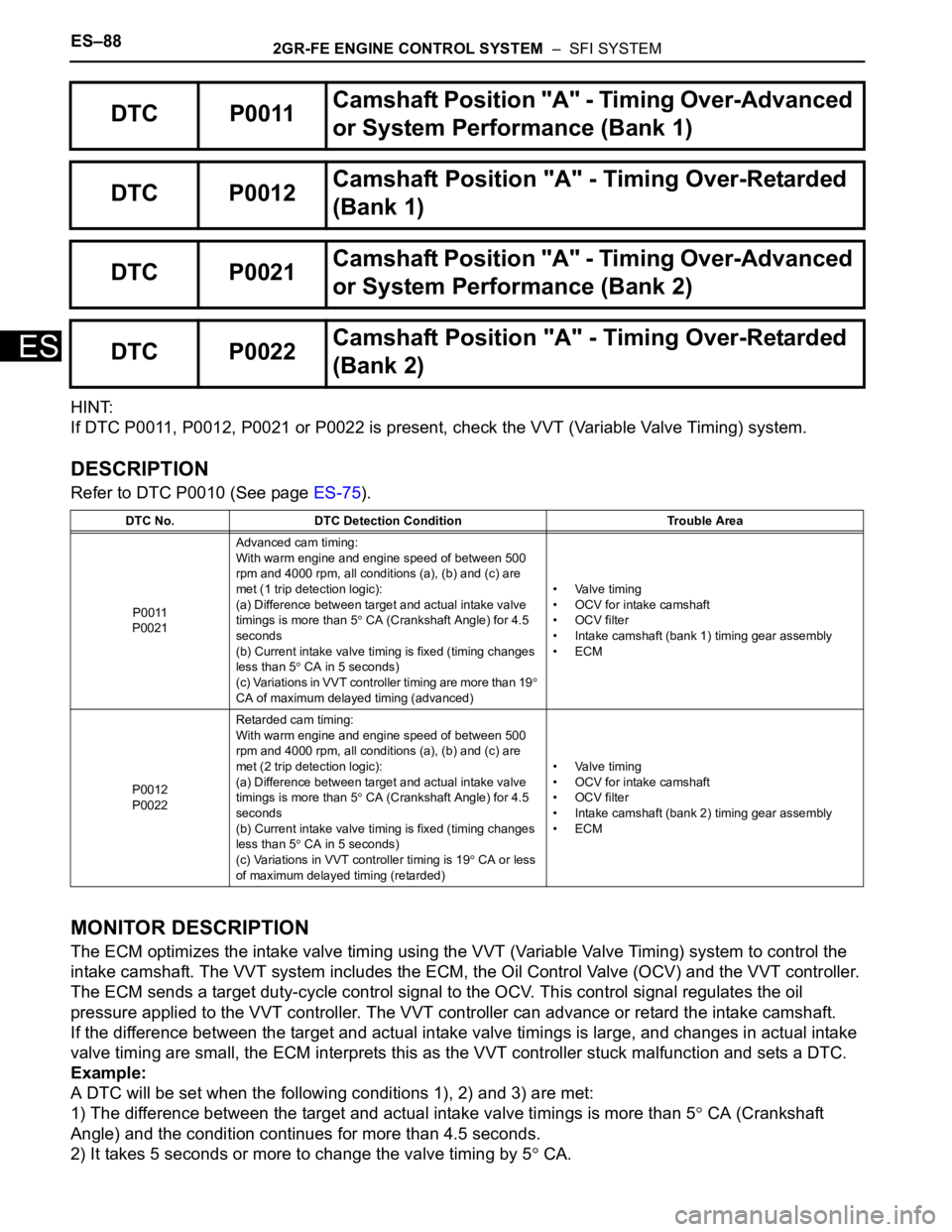
WIRING DIAGRAM
INSPECTION PROCEDURE
HINT:
• If DTC P0010 is displayed, check the intake camshaft circuit for the right bank VVT system.
• Bank 1 refers to the bank that includes cylinder No. 1.
• If DTC P0020 is displayed, check the intake camshaft circuit for the left bank VVT system.
• Bank 2 refers to the bank that does not include cylinder No. 1.
• Read freeze frame data using the intelligent tester. The ECM records vehicle and driving condition
information as freeze frame data the moment a DTC is stored. When troubleshooting, freeze frame
data can be helpful in determining whether the vehicle was running or stopped, whether the engine
was warmed up or not, whether the air-fuel ratio was lean or rich, as well as other data recorded at the
time of a malfunction.
(a) Connect the intelligent tester to the DLC3.
(b) Start the engine and turn the tester on.
(c) Warm up the engine.
(d) On the tester, enter the following menus: DIAGNOSIS /
ENHANCED OBD II / ACTIVE TEST / VVT CTRL B1 or
VVT CTRL B2.
(e) Check the engine speed while operating the Oil Control
Valve (OCV) using the tester.
1PERFORM ACTIVE TEST BY CAMSHAFT TIMING OIL CONTROL VALVE ASSEMBLY
(OCV)
A133849E05
Page 392 of 3000
ES–862GR-FE ENGINE CONTROL SYSTEM – SFI SYSTEM
ES
OK
OK
NG
(a) Disconnect the C23 or C24 camshaft timing oil control
valve (OCV) connector.
(b) Measure the resistance according to the value(s) in the
table below.
Standard resistance
(c) Reconnect the OCV connector.
NG
OK
Tester Operation Specified Condition
OCV OFF Normal engine speed
OCV ON Engine idles roughly or stalls (soon after OCV switched from OFF to ON)
CHECK FOR INTERMITTENT PROBLEMS
(See page ES-13)
2INSPECT CAMSHAFT TIMING OIL CONTROL VALVE ASSEMBLY
A095415E03
Tester Connection Condition Specified Condition
1 - 2 20
C (68F) 6.9 to 7.9
REPLACE CAMSHAFT TIMING OIL
CONTROL VALVE ASSEMBLY (See page ES-
486)
Page 393 of 3000
2GR-FE ENGINE CONTROL SYSTEM – SFI SYSTEMES–87
ES
(a) Disconnect the C23 or C24 camshaft timing oil control
valve (OCV) connector.
(b) Disconnect the E11 ECM connector.
(c) Measure the resistance according to the value(s) in the
table below.
Standard resistance (Check for open)
Standard resistance (Check for short)
(d) Reconnect the OCV connector.
(e) Reconnect the ECM connector.
NG
OK
3CHECK HARNESS AND CONNECTOR (OCV - ECM)
A162359E01
Tester Connection Specified Condition
OC1+ (E11-17) - C23-1 Below 1
OC1- (E11-16) - C23-2 Below 1
OC2+ (E11-15) - C24-1 Below 1
OC2- (E11-14) - C24-2 Below 1
Tester Connection Specified Condition
OC1+ (E11-17) or C23-1 - Body ground 10 k
or higher
OC1- (E11-16) or C23-2 - Body ground 10 k
or higher
OC2+ (E11-15) or C24-1 - Body ground 10 k
or higher
OC2- (E11-14) or C24-2 - Body ground 10 k
or higher
REPAIR OR REPLACE HARNESS OR
CONNECTOR (OCV - ECM)
REPLACE ECM (See page ES-498)
Page 394 of 3000

ES–882GR-FE ENGINE CONTROL SYSTEM – SFI SYSTEM
ES
HINT:
If DTC P0011, P0012, P0021 or P0022 is present, check the VVT (Variable Valve Timing) system.
DESCRIPTION
Refer to DTC P0010 (See page ES-75).
MONITOR DESCRIPTION
The ECM optimizes the intake valve timing using the VVT (Variable Valve Timing) system to control the
intake camshaft. The VVT system includes the ECM, the Oil Control Valve (OCV) and the VVT controller.
The ECM sends a target duty-cycle control signal to the OCV. This control signal regulates the oil
pressure applied to the VVT controller. The VVT controller can advance or retard the intake camshaft.
If the difference between the target and actual intake valve timings is large, and changes in actual intake
valve timing are small, the ECM interprets this as the VVT controller stuck malfunction and sets a DTC.
Example:
A DTC will be set when the following conditions 1), 2) and 3) are met:
1) The difference between the target and actual intake valve timings is more than 5
CA (Crankshaft
Angle) and the condition continues for more than 4.5 seconds.
2) It takes 5 seconds or more to change the valve timing by 5
CA.
DTC P0011Camshaft Position "A" - Timing Over-Advanced
or System Performance (Bank 1)
DTC P0012Camshaft Position "A" - Timing Over-Retarded
(Bank 1)
DTC P0021Camshaft Position "A" - Timing Over-Advanced
or System Performance (Bank 2)
DTC P0022Camshaft Position "A" - Timing Over-Retarded
(Bank 2)
DTC No. DTC Detection Condition Trouble Area
P0011
P0021Advanced cam timing:
With warm engine and engine speed of between 500
rpm and 4000 rpm, all conditions (a), (b) and (c) are
met (1 trip detection logic):
(a) Difference between target and actual intake valve
timings is more than 5
CA (Crankshaft Angle) for 4.5
seconds
(b) Current intake valve timing is fixed (timing changes
less than 5
CA in 5 seconds)
(c) Variations in VVT controller timing are more than 19
CA of maximum delayed timing (advanced)• Valve timing
• OCV for intake camshaft
• OCV filter
• Intake camshaft (bank 1) timing gear assembly
•ECM
P0012
P0022Retarded cam timing:
With warm engine and engine speed of between 500
rpm and 4000 rpm, all conditions (a), (b) and (c) are
met (2 trip detection logic):
(a) Difference between target and actual intake valve
timings is more than 5
CA (Crankshaft Angle) for 4.5
seconds
(b) Current intake valve timing is fixed (timing changes
less than 5
CA in 5 seconds)
(c) Variations in VVT controller timing is 19
CA or less
of maximum delayed timing (retarded)• Valve timing
• OCV for intake camshaft
• OCV filter
• Intake camshaft (bank 2) timing gear assembly
•ECM
Page 396 of 3000

ES–902GR-FE ENGINE CONTROL SYSTEM – SFI SYSTEM
ES
HINT:
• If DTC P0011 or P0012 is displayed, check the bank 1 VVT system circuit.
• Bank 1 refers to the bank that includes cylinder No. 1.
• If DTC P0021 or P0022 is displayed, check the bank 2 VVT system circuit.
• Bank 2 refers to the bank that does not include cylinder No. 1.
• Read freeze frame data using the intelligent tester. The ECM records vehicle and driving condition
information as freeze frame data the moment a DTC is stored. When troubleshooting, freeze frame
data can be helpful in determining whether the vehicle was running or stopped, whether the engine
was warmed up or not, whether the air-fuel ratio was lean or rich, as well as other data recorded at the
time of a malfunction.
(a) Connect the intelligent tester to the DLC3.
(b) Turn the ignition switch to the ON position and turn the
tester on.
(c) Select the following menu items: DIAGNOSIS /
ENHANCED OBD II / DTC INFO / CURRENT CODES.
(d) Read the DTCs.
Result
HINT:
If any DTCs other than P0011, P0012, P0021 or P0022
are output, troubleshoot those DTCs first.
B
A
(a) Connect the intelligent tester to the DLC3.
(b) Start the engine and turn the tester on.
(c) Warm up the engine.
(d) Select the following menu items on the tester:
DIAGNOSIS / ENHANCED OBD II / ACTIVE TEST /
VVT CTRL B1.
(e) Check the engine speed while operating the Oil Control
Valve (OCV) using the tester.
OK
NG
OK
1CHECK ANY OTHER DTCS OUTPUT (IN ADDITION TO DTC P0011, P0012, P0021 OR
P0022)
Display (DTC Output) Proceed to
P0011, P0012, P0021 or P0022 A
P0011, P0012, P0021 or P0022 and other DTCs B
GO TO DTC CHART (See page ES-56)
2PERFORM ACTIVE TEST BY INTELLIGENT TESTER (OPERATE OCV)
Tester Operation Specified Condition
OCV OFF Normal engine idle speed
OCV ON Engine idles roughly or stalls (soon after OCV switched from OFF to ON)
Go to step 4
Page 398 of 3000
ES–922GR-FE ENGINE CONTROL SYSTEM – SFI SYSTEM
ES
(a) Remove the cylinder head covers RH and LH.
(b) Turn the crankshaft to align the timing marks of the
crankshaft.
(c) Align the notch of the crankshaft pulley to the "0"
position.
(d) Check if the timing marks of the camshaft pulley and
camshaft bearing cap align.
(e) Turn the crankshaft clockwise by 360
if the timing marks
do not align. Check if they align once again.
OK:
The timing marks of the camshaft pulley and the
camshaft bearing cap align when the notch of the
crankshaft pulley is in the "0" position.
NG
OK
(a) Remove the camshaft timing oil control valve (OCV).
(b) Measure the resistance according to the value(s) in the
table below.
Standard resistance
4CHECK VALVE TIMING (CHECK FOR LOOSE AND JUMPED TEETH ON TIMING CHAIN)
A135015E01
ADJUST VALVE TIMING
5INSPECT CAMSHAFT TIMING OIL CONTROL VALVE ASSEMBLY (OCV)
A095415E03
Tester Connection Condition Specified Condition
1 - 2 20
C (68F) 6.9 to 7.9