Page 2802 of 3000

AIR CONDITIONING – AIR CONDITIONING SYSTEM (for Automatic Air Conditioning Sys-
tem)AC–59
AC
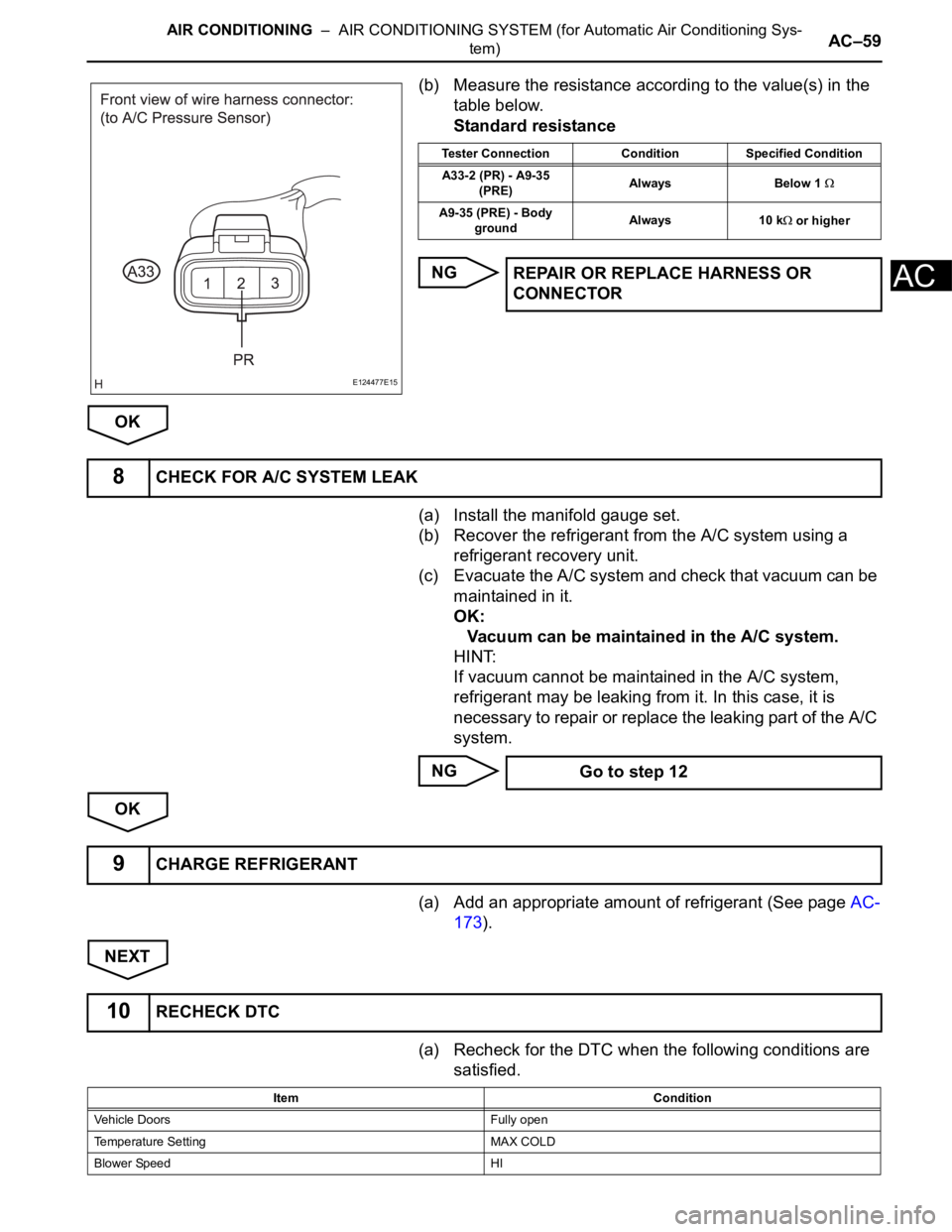
(b) Measure the resistance according to the value(s) in the
table below.
Standard resistance
NG
OK
(a) Install the manifold gauge set.
(b) Recover the refrigerant from the A/C system using a
refrigerant recovery unit.
(c) Evacuate the A/C system and check that vacuum can be
maintained in it.
OK:
Vacuum can be maintained in the A/C system.
HINT:
If vacuum cannot be maintained in the A/C system,
refrigerant may be leaking from it. In this case, it is
necessary to repair or replace the leaking part of the A/C
system.
NG
OK
(a) Add an appropriate amount of refrigerant (See page AC-
173).
NEXT
(a) Recheck for the DTC when the following conditions are
satisfied.
E124477E15
Tester Connection Condition Specified Condition
A33-2 (PR) - A9-35
(PRE)Always Below 1
A9-35 (PRE) - Body
groundAlways 10 k or higher
REPAIR OR REPLACE HARNESS OR
CONNECTOR
8CHECK FOR A/C SYSTEM LEAK
Go to step 12
9CHARGE REFRIGERANT
10RECHECK DTC
Item Condition
Vehicle Doors Fully open
Temperature Setting MAX COLD
Blower Speed HI
Page 2803 of 3000

AC–60AIR CONDITIONING – AIR CONDITIONING SYSTEM (for Automatic Air Conditioning Sys-
tem)
AC
NOTICE:
If refrigerant pressure on the high pressure side
becomes high, the DTC will be set. It is necessary to
measure the voltage for a certain amount of time
(approximately 10 minutes) because the DTC may be
set after the A/C operates for a while.
HINT:
When the outside air temperature is low (below -1.5
C
(29.3
F)), the compressor stops due to operation of the
ambient temperature sensor and the evaporator
temperature sensor to prevent the evaporator from
freezing. In this case, perform the inspection in a warm
indoor environment.
Result
NOTICE:
If the DTC was set due to an insufficient or excessive
amount of refrigerant, the problem may have been
solved after performing the previous step. However,
the root cause of insufficient refrigerant may be
refrigerant leaks. The root cause of excessive
refrigerant may be adding refrigerant when the level
was insufficient. Therefore, identify and repair the
area where refrigerant leaks from as necessary.
B
A
(a) Install the manifold gauge set.
(b) Disconnect the connector from the A/C pressure sensor.
A/C Switch ON
R/F Switch RECIRCULATION
Interior Temperature 25 to 35
C (77 to 95F)
Engine Speed 2000 rpmItem Condition
Result Proceed to
DTC B1423 is output A
DTC B1423 is not output B
END
11INSPECT A/C PRESSURE SENSOR
Page 2808 of 3000
AIR CONDITIONING – AIR CONDITIONING SYSTEM (for Automatic Air Conditioning Sys-
tem)AC–65
AC
DESCRIPTION
The solar sensor, which is installed on the upper side of the instrument panel, detects sunlight and
controls the air conditioning in AUTO mode. The output voltage from the solar sensor varies according to
the amount of sunlight. When the sunlight increases, the output voltage increases. As the sunlight
decreases, the output voltage decreases. The A/C amplifier detects output voltage from the solar sensor.
DTC B1424/24 Solar Sensor Circuit (Driver Side)
DTC No. DTC Detection Condition Trouble Area
B1424/24 Open or short in driver side solar sensor circuit•Solar sensor
• Harness or connector between solar sensor and A/
C amplifier
• Harness or connector between solar sensor and
body ECU
• A/C amplifier
• Body ECU
E107008E01
Page 2880 of 3000
AIR CONDITIONING – AIR CONDITIONING SYSTEM (for Automatic Air Conditioning Sys-
tem)AC–137
AC
OK
(a) Remove the MG CLT relay from the No. 3 relay block.
(b) Measure the resistance according to the value(s) in the
table below.
Standard resistance
(c) Install the MG CLT relay to the No. 3 relay block.
NG
OK
(a) Disconnect the connector from the A/C amplifier.
(b) Measure the voltage according to the value(s) in the
table below.
Standard voltage
NG
OK
5INSPECT RELAY (MG CLT)
B060778E04
Tester Connection Specified Condition
3 - 5 10 k
or higher
3 - 5Below 1
(when battery voltage is applied to terminals 1 and 2)
REPLACE RELAY (MG CLT)
6CHECK HARNESS AND CONNECTOR (A/C AMPLIFIER - BATTERY)
E143742E44
Tester Connection Condition Specified Condition
A9-5 (MGC) - Body
groundIgnition switch: OFF Below 1 V
A9-5 (MGC) - Body
groundIgnition switch: ON 11 to 14 V
REPAIR OR REPLACE HARNESS OR
CONNECTOR
Page 2926 of 3000

AC–182AIR CONDITIONING – AIR CONDITIONING UNIT
AC
REMOVAL
1. RECOVER REFRIGERANT FROM REFRIGERATION
SYSTEM (See page AC-172)
2. REMOVE FRONT WIPER ARM HEAD CAP (See page
WW-4)
3. REMOVE FRONT WIPER ARM RH (See page WW-4)
4. REMOVE FRONT WIPER ARM LH (See page WW-4)
5. REMOVE COWL TOP VENTILATOR LOUVER SUB-
ASSEMBLY (See page WW-4)
6. REMOVE WINDSHIELD WIPER MOTOR AND LINK
ASSEMBLY (See page WW-4)
7. REMOVE FRONT COWL TOP OUTER PANEL SUB-
ASSEMBLY (See page SP-13)
8. DISCONNECT COOLER REFRIGERANT LIQUID PIPE
E (TO COOLER UNIT)
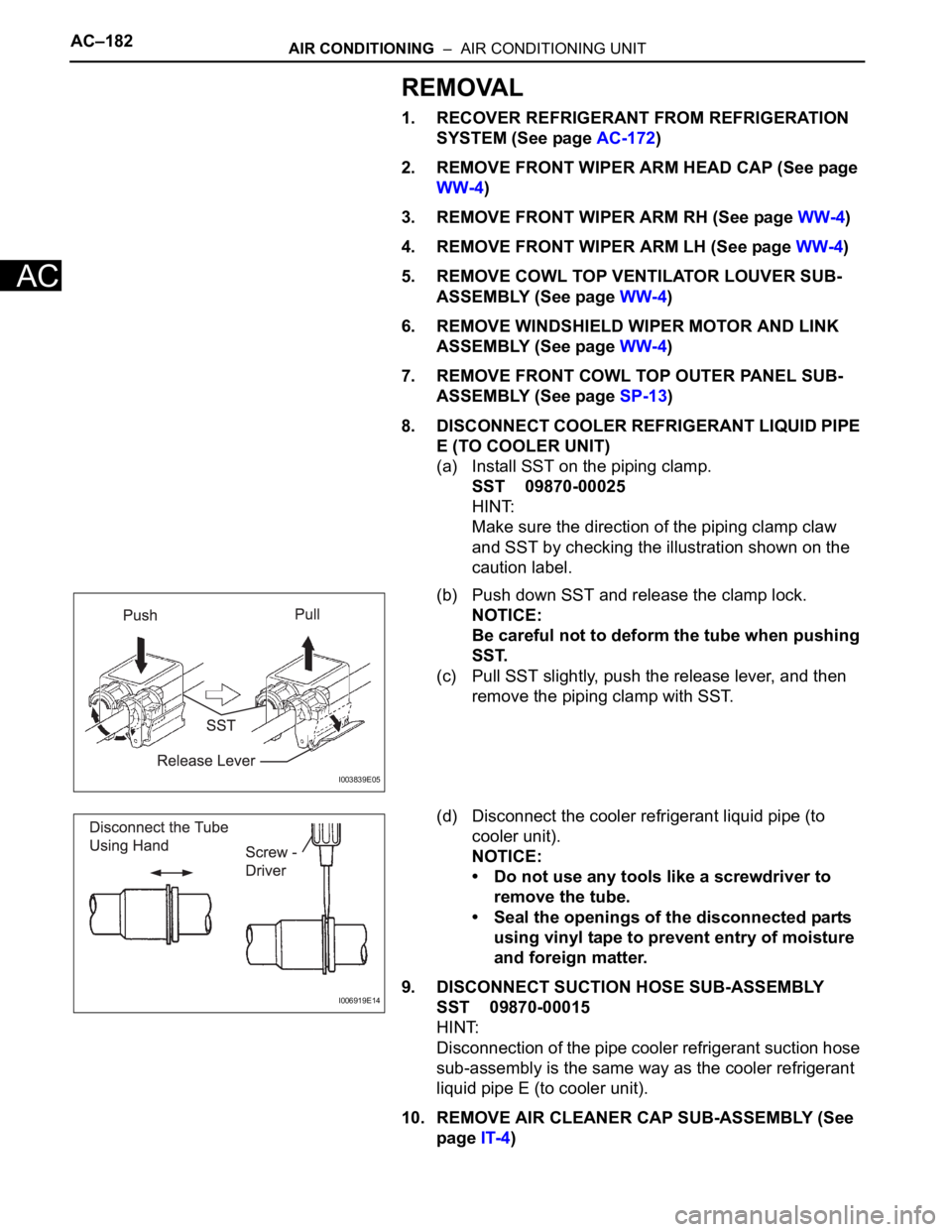
(a) Install SST on the piping clamp.
SST 09870-00025
HINT:
Make sure the direction of the piping clamp claw
and SST by checking the illustration shown on the
caution label.
(b) Push down SST and release the clamp lock.
NOTICE:
Be careful not to deform the tube when pushing
SST.
(c) Pull SST slightly, push the release lever, and then
remove the piping clamp with SST.
(d) Disconnect the cooler refrigerant liquid pipe (to
cooler unit).
NOTICE:
• Do not use any tools like a screwdriver to
remove the tube.
• Seal the openings of the disconnected parts
using vinyl tape to prevent entry of moisture
and foreign matter.
9. DISCONNECT SUCTION HOSE SUB-ASSEMBLY
SST 09870-00015
HINT:
Disconnection of the pipe cooler refrigerant suction hose
sub-assembly is the same way as the cooler refrigerant
liquid pipe E (to cooler unit).
10. REMOVE AIR CLEANER CAP SUB-ASSEMBLY (See
page IT-4)
I003839E05
I006919E14
Page 2937 of 3000

AIR CONDITIONING – AIR CONDITIONING SYSTEM (for Automatic Air Conditioning Sys-
tem)AC–29
AC
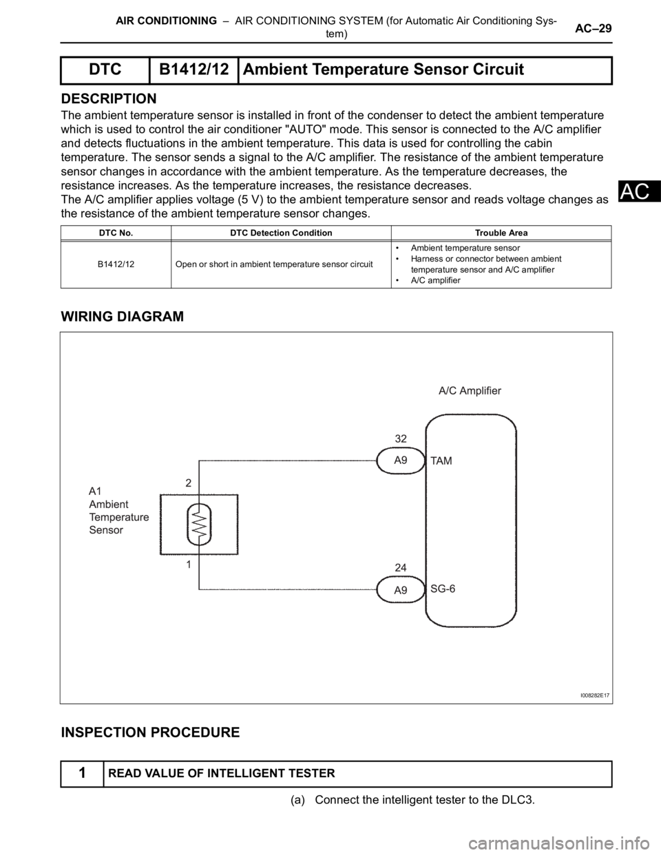
DESCRIPTION
The ambient temperature sensor is installed in front of the condenser to detect the ambient temperature
which is used to control the air conditioner "AUTO" mode. This sensor is connected to the A/C amplifier
and detects fluctuations in the ambient temperature. This data is used for controlling the cabin
temperature. The sensor sends a signal to the A/C amplifier. The resistance of the ambient temperature
sensor changes in accordance with the ambient temperature. As the temperature decreases, the
resistance increases. As the temperature increases, the resistance decreases.
The A/C amplifier applies voltage (5 V) to the ambient temperature sensor and reads voltage changes as
the resistance of the ambient temperature sensor changes.
WIRING DIAGRAM
INSPECTION PROCEDURE
(a) Connect the intelligent tester to the DLC3.
DTC B1412/12 Ambient Temperature Sensor Circuit
DTC No. DTC Detection Condition Trouble Area
B1412/12 Open or short in ambient temperature sensor circuit• Ambient temperature sensor
• Harness or connector between ambient
temperature sensor and A/C amplifier
• A/C amplifier
1READ VALUE OF INTELLIGENT TESTER
I008282E17
Page 2945 of 3000
AIR CONDITIONING – BLOWER UNIT (for Rear Air Conditioning System)AC–207
AC
(c) Remove the 3 screws and the heater water valve
assembly.
(d) Remove the 2 O-rings from the heater water valve
assembly.
(e) Remove the heater radiator unit sub-assembly from
the air conditioning blower assembly.
REASSEMBLY
1. INSTALL HEATER RADIATOR UNIT SUB-ASSEMBLY
(a) Install the heater radiator unit sub-assembly to the
air conditioning blower assembly.
(b) Install the 2 O-rings to the heater water valve
assembly.
(c) Install the 3 screws and the heater water valve
assembly.
(d) Install the 2 screws and the 2 clamps.
E055397
E062465
E062465
E055397
E055396
Page 2946 of 3000

AIR CONDITIONING – AIR CONDITIONING SYSTEM (for Automatic Air Conditioning Sys-
tem)AC–33
AC
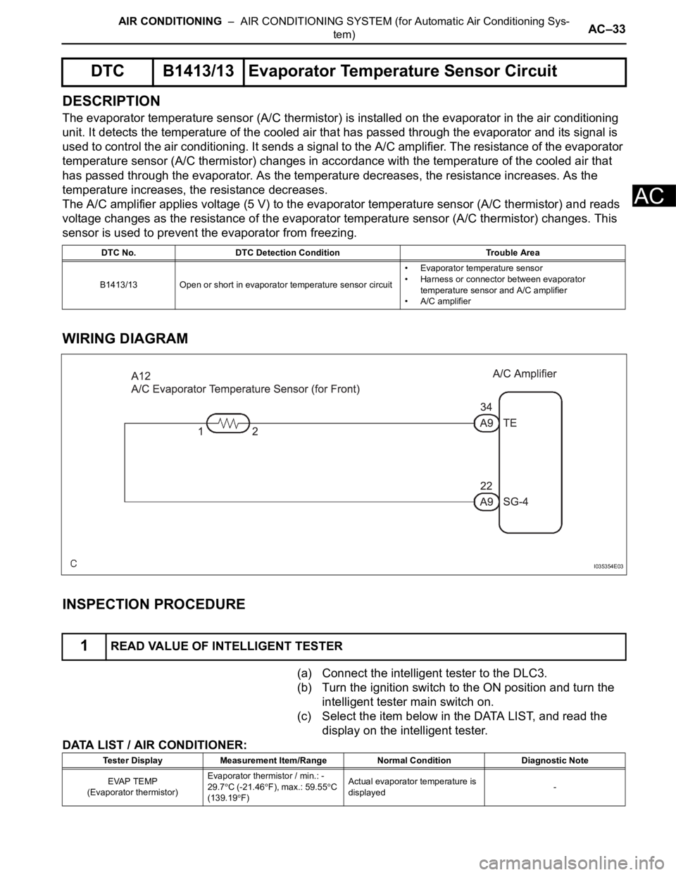
DESCRIPTION
The evaporator temperature sensor (A/C thermistor) is installed on the evaporator in the air conditioning
unit. It detects the temperature of the cooled air that has passed through the evaporator and its signal is
used to control the air conditioning. It sends a signal to the A/C amplifier. The resistance of the evaporator
temperature sensor (A/C thermistor) changes in accordance with the temperature of the cooled air that
has passed through the evaporator. As the temperature decreases, the resistance increases. As the
temperature increases, the resistance decreases.
The A/C amplifier applies voltage (5 V) to the evaporator temperature sensor (A/C thermistor) and reads
voltage changes as the resistance of the evaporator temperature sensor (A/C thermistor) changes. This
sensor is used to prevent the evaporator from freezing.
WIRING DIAGRAM
INSPECTION PROCEDURE
(a) Connect the intelligent tester to the DLC3.
(b) Turn the ignition switch to the ON position and turn the
intelligent tester main switch on.
(c) Select the item below in the DATA LIST, and read the
display on the intelligent tester.
DATA LIST / AIR CONDITIONER:
DTC B1413/13 Evaporator Temperature Sensor Circuit
DTC No. DTC Detection Condition Trouble Area
B1413/13 Open or short in evaporator temperature sensor circuit• Evaporator temperature sensor
• Harness or connector between evaporator
temperature sensor and A/C amplifier
• A/C amplifier
1READ VALUE OF INTELLIGENT TESTER
I035354E03
Tester Display Measurement Item/Range Normal Condition Diagnostic Note
EVAP TEMP
(Evaporator thermistor)Evaporator thermistor / min.: -
29.7
C (-21.46F), max.: 59.55C
(139.19F)Actual evaporator temperature is
displayed-