2007 NISSAN TIIDA parking brake
[x] Cancel search: parking brakePage 4414 of 5883

PB-10
< SERVICE DATA AND SPECIFICATIONS (SDS)
SERVICE DATA AND SPECIFICATIONS (SDS)
SERVICE DATA AND SPECIFICATIONS (SDS)
SERVICE DATA AND SPECIFICATIONS (SDS)
Parking Brake ControlINFOID:0000000001716780
Parking Drum BrakeINFOID:0000000001724715
Control typeHand lever
Number of notches [under a force of 196 N (20 kg-f, 44lb-f)] 8 −9
Number of notches when warning lamp switch comes on 1
Brake liningStandard thickness (new) 3.2 mm (0.126 in)
Wear limit thickness 1.5 mm (0.059 in)
Drum (disc)Standard inner diameter (new) 172 mm (6.77 in)
Wear limit of inner diameter 173 mm (6.81 in)
Page 4533 of 5883

RAX-6
< ON-VEHICLE REPAIR >
WHEEL HUB
ON-VEHICLE REPAIR
WHEEL HUB
Removal and InstallationINFOID:0000000001724589
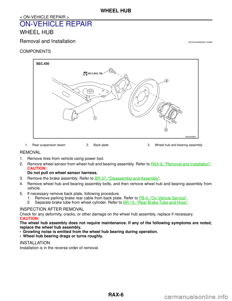
COMPONENTS
REMOVAL
1. Remove tires from vehicle using power tool.
2. Remove wheel sensor from wheel hub and bearing assembly. Refer to RAX-6, "
Removal and Installation".
CAUTION:
Do not pull on wheel sensor harness.
3. Remove the brake assembly. Refer to BR-37, "
Disassembly and Assembly".
4. Remove wheel hub and bearing assembly bolts, and then remove wheel hub and bearing assembly from
vehicle.
5. If necessary remove back plate, following procedure.
1. Remove parking brake rear cable from back plate. Refer to PB-4, "
On-Vehicle Service".
2. Separate brake tube from wheel cylinder. Refer to BR-15, "
Rear Brake Tube and Hose".
INSPECTION AFTER REMOVAL
Check for any deformity, cracks, or other damage on the wheel hub assembly, replace if necessary.
CAUTION:
The wheel hub assembly does not require maintenance. If any of the following symptoms are noted,
replace the wheel hub assembly.
Growling noise is emitted from the wheel hub bearing during operation.
Wheel hub bearing drags or turns roughly.
INSTALLATION
Installation is in the reverse order of removal.
1. Rear suspension beam 2. Back plate 3. Wheel hub and bearing assembly
WDIA0360E
Page 4583 of 5883

REAR SUSPENSION BEAM
RSU-11
< ON-VEHICLE REPAIR >
C
D
F
G
H
I
J
K
L
MA
B
RSU
N
O
P
REAR SUSPENSION BEAM
Removal and InstallationINFOID:0000000001724580
REMOVAL
1. Remove rear tires from vehicle using power tool.
2. Separate parking brake rear cable from rear drum brake and rear suspension beam. Refer to PB-4, "
On-
Vehicle Service" .
3. Remove wheel sensor and wheel sensor harness from wheel hub and bearing assembly and rear suspen-
sion beam. Refer to BRC-83, "
Removal and Installation" .
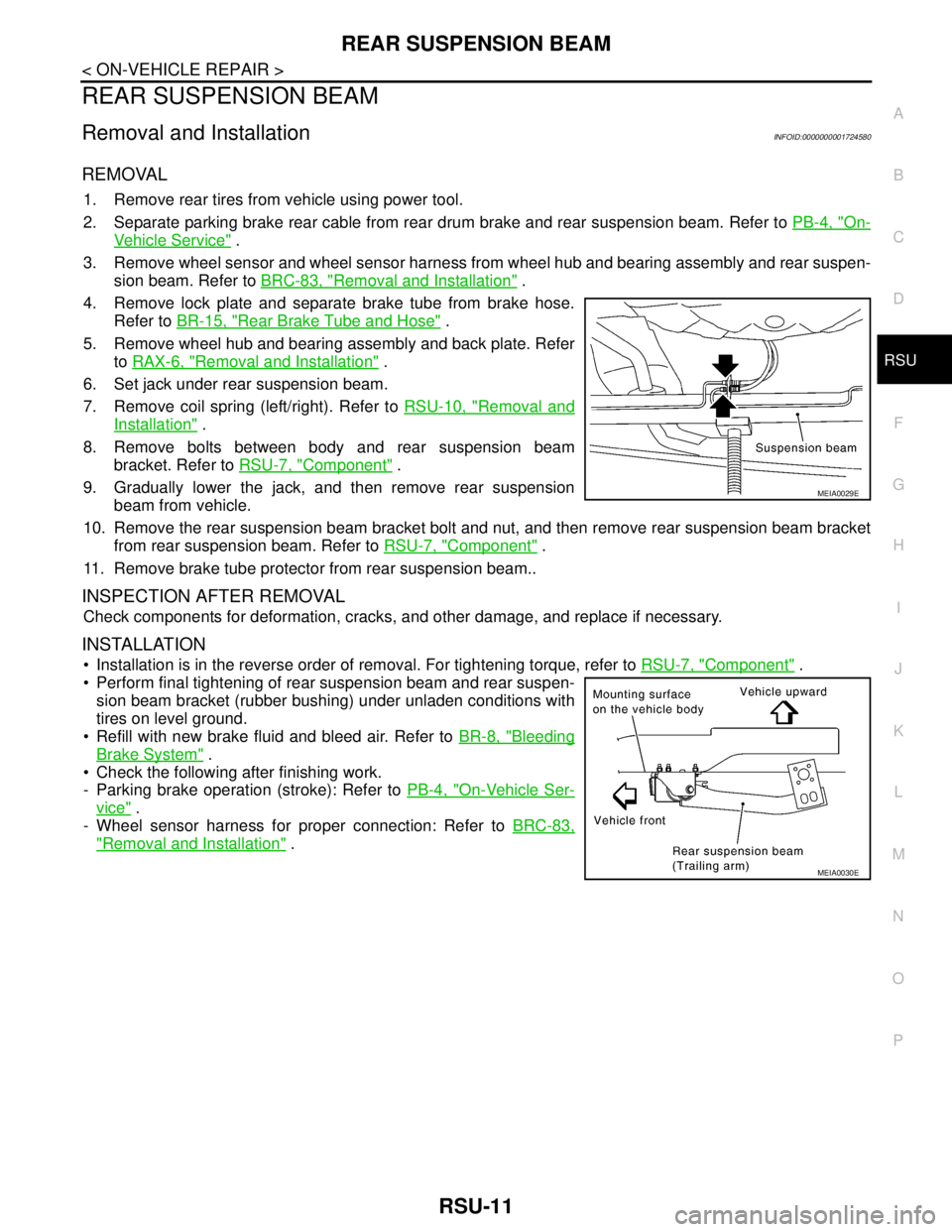
4. Remove lock plate and separate brake tube from brake hose.
Refer to BR-15, "
Rear Brake Tube and Hose" .
5. Remove wheel hub and bearing assembly and back plate. Refer
to RAX-6, "
Removal and Installation" .
6. Set jack under rear suspension beam.
7. Remove coil spring (left/right). Refer to RSU-10, "
Removal and
Installation" .
8. Remove bolts between body and rear suspension beam
bracket. Refer to RSU-7, "
Component" .
9. Gradually lower the jack, and then remove rear suspension
beam from vehicle.
10. Remove the rear suspension beam bracket bolt and nut, and then remove rear suspension beam bracket
from rear suspension beam. Refer to RSU-7, "
Component" .
11. Remove brake tube protector from rear suspension beam..
INSPECTION AFTER REMOVAL
Check components for deformation, cracks, and other damage, and replace if necessary.
INSTALLATION
Installation is in the reverse order of removal. For tightening torque, refer to RSU-7, "Component" .
Perform final tightening of rear suspension beam and rear suspen-
sion beam bracket (rubber bushing) under unladen conditions with
tires on level ground.
Refill with new brake fluid and bleed air. Refer to BR-8, "
Bleeding
Brake System" .
Check the following after finishing work.
- Parking brake operation (stroke): Refer to PB-4, "
On-Vehicle Ser-
vice" .
- Wheel sensor harness for proper connection: Refer to BRC-83,
"Removal and Installation" .
MEIA0029E
MEIA0030E
Page 4588 of 5883

SB-4
< BASIC INSPECTION >
INSPECTION
6. Repeat steps above as necessary to check the other seat belts.
SEAT BELT RETRACTOR ON-VEHICLE CHECK
Emergency Locking Retractors (ELR) and Automatic Locking Retractors (ALR)
NOTE:
All seat belt retractors are of the Emergency Locking Retractors (ELR) type. In an emergency (sudden stop)
the retractor will lock and prevent the webbing from extending any further. All 3-point type seat belt retractors
except the driver's seat belt also have an Automatic Locking Retractors (ALR) mode. The ALR mode (also
called child restraint mode) is used when installing child seats. The ALR mode is activated when the seat belt
is fully extended. When the webbing is then retracted partially, the ALR mode automatically locks the seat belt
in a specific position so the webbing cannot be extended any further. To cancel the ALR mode, allow the seat
belt to fully wind back into the retractor.
Check the seat belt retractors using the following test(s) to determine if a retractor assembly is operating prop-
erly.
ELR Function Stationary Check
Grasp the shoulder webbing and pull it forward quickly. The retractor should lock and prevent the belt from
extending further.
ALR Function Stationary Check
1. Pull out entire length of seat belt from retractor until a click is heard.
2. Retract the webbing partially. A clicking noise should be heard as the webbing retracts, indicating that the
retractor is in the Automatic Locking Retractors (ALR) mode.
3. Grasp the seat belt and try to pull out the retractor. The webbing must lock and not extend any further. If
NG, replace the retractor assembly.
4. Allow the entire length of the webbing to retract to cancel the automatic locking mode.
ELR Function Moving Check
WARNING:
Perform the following test in a safe, open area clear of other vehicles and obstructions (for example, a
large, empty parking lot). Road surface must be paved and dry. DO NOT perform the following test on
wet or gravel roads or on public streets and highways. This could result in an accident and serious
personal injury. The driver and passenger must be prepared to brace themselves in the event the
retractor does not lock.
1. Fasten driver's seat belt. Buckle a passenger into the seat for the belt that is to be tested.
2. Proceed to the designated safe area.
3. Drive the vehicle at approximately 16 km/h (10 MPH). Notify any passengers of a pending sudden stop
and the driver and passenger must be prepared to brace themselves in the event the retractor does not
lock, apply brakes firmly and make a very hard stop.
During the stop, seat belts should lock and not be extended. If the seat belt retractor assembly does not lock,
perform the retractor off-vehicle check.
SEAT BELT RETRACTOR OFF-VEHICLE CHECK
1. Remove the seat belt retractor. Refer to SB-6, "Removal and Installation of Front Seat Belt".
Page 4861 of 5883

ST-6
< ON-VEHICLE MAINTENANCE >
STEERING WHEEL
ON-VEHICLE MAINTENANCE
STEERING WHEEL
On-Vehicle Inspection and ServiceINFOID:0000000001282496
CHECKING CONDITION OF INSTALLATION
Check installation conditions of steering gear assembly, front suspension assembly, axle and steering col-
umn assembly.
Check if movement exists when steering wheel is moved up and down, to the left and right and to the axial
direction.
Check steering gear assembly mounting bolts and nuts for looseness. Refer to ST-12, "
Removal and Instal-
lation" .
CHECKING STEERING WHEEL PLAY
Turn steering wheel so that front wheels come to the straight-ahead position. Start engine and lightly turn
steering wheel to the left and right until front wheels start to move. Measure steering wheel movement on the
outer circumference.
When the measurement value is outside the standard value, check backlash for each joint of steering col-
umn assembly and installation condition of steering gear assembly.
CHECKING NEUTRAL POSITION STEERING WHEEL
Make sure that steering gear assembly, steering column assembly and steering wheel are installed in the
correct position.
Perform neutral position inspection after wheel alignment. Refer to SR-2, "
Precaution for Supplemental
Restraint System (SRS) "AIR BAG" and "SEAT BELT PRE-TENSIONER"" .
Set vehicle to the straight-ahead position and confirm steering wheel is in the neutral position.
Loosen outer socket lock nut and turn inner socket to left and right equally to make fine adjustments if steer-
ing wheel is not in the neutral position.
CHECKING STEERING WHEEL TURNING FORCE
1. Park vehicle on a level and dry surface, set parking brake.
2. Start engine.
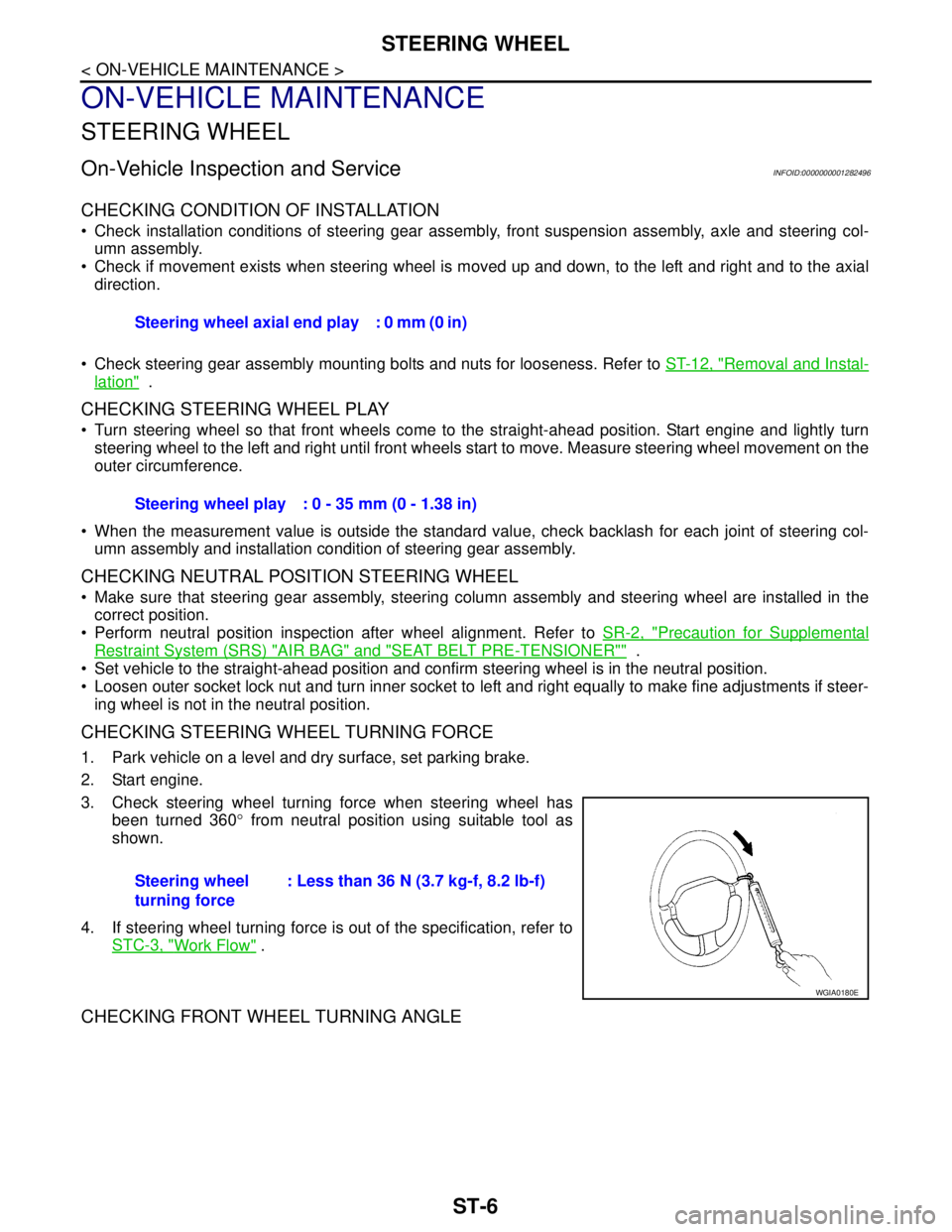
3. Check steering wheel turning force when steering wheel has
been turned 360° from neutral position using suitable tool as
shown.
4. If steering wheel turning force is out of the specification, refer to
STC-3, "
Work Flow" .
CHECKING FRONT WHEEL TURNING ANGLE
Steering wheel axial end play : 0 mm (0 in)
Steering wheel play : 0 - 35 mm (0 - 1.38 in)
Steering wheel
turning force: Less than 36 N (3.7 kg-f, 8.2 lb-f)
WGIA0180E
Page 4960 of 5883
![NISSAN TIIDA 2007 Service Repair Manual TM-14
< FUNCTION DIAGNOSIS >[TYPE 1 (4AT: RE4F03B)]
A/T CONTROL SYSTEM
Shift Mechanism
INFOID:0000000001694421
CONSTRUCTION
FUNCTION OF CLUTCH AND BRAKE
CLUTCH AND BAND CHART
1. Torque converter 2. Oi NISSAN TIIDA 2007 Service Repair Manual TM-14
< FUNCTION DIAGNOSIS >[TYPE 1 (4AT: RE4F03B)]
A/T CONTROL SYSTEM
Shift Mechanism
INFOID:0000000001694421
CONSTRUCTION
FUNCTION OF CLUTCH AND BRAKE
CLUTCH AND BAND CHART
1. Torque converter 2. Oi](/manual-img/5/57395/w960_57395-4959.png)
TM-14
< FUNCTION DIAGNOSIS >[TYPE 1 (4AT: RE4F03B)]
A/T CONTROL SYSTEM
Shift Mechanism
INFOID:0000000001694421
CONSTRUCTION
FUNCTION OF CLUTCH AND BRAKE
CLUTCH AND BAND CHART
1. Torque converter 2. Oil pump 3. Input shaft
4. Brake band 5. Reverse clutch 6. High clutch
7. Front sun gear 8. Front pinion gear 9. Front internal gear
10. Front planetary carrier 11. Rear sun gear 12. Rear pinion gear
13. Rear internal gear 14. Rear planetary carrier 15. Forward clutch
16. Forward one-way clutch 17. Overrun clutch 18. Low one-way clutch
19. Low & reverse brake 20. Parking pawl 21. Parking gear
22. Output shaft 23. Idle gear 24. Output gear
SAT998I
Clutch and brake components Abbr. Function
5Reverse clutch R/C To transmit input power to front sun gear 7.
6High clutch H/C To transmit input power to front planetary carrier 10.
15Forward clutch F/C To connect front planetary carrier 10 with forward one-way clutch 16.
17Overrun clutch O/C To connect front planetary carrier 10 with rear internal gear 13.
4Brake band B/B To lock front sun gear 7.
16Forward one-way clutch F/O.CWhen forward clutch 15 is engaged, to stop rear internal gear 13 from rotating in
opposite direction against engine revolution.
18Low one-way clutch L/O.CTo stop front planetary carrier 10 from rotating in opposite direction against en-
gine revolution.
19Low & reverse brake L & R/B To lock front planetary carrier 10.
Shift posi-
tionR/C
5H/C
6F/C
15O/C
17Band servo
F/O.C
16L/O.C
18L&R/B
19Lock-
upRemarks
2nd
apply3rd re-
lease4th ap-
ply
PPA R K
POSITION
RREVERSE
POSITION
Page 4962 of 5883
![NISSAN TIIDA 2007 Service Repair Manual TM-16
< FUNCTION DIAGNOSIS >[TYPE 1 (4AT: RE4F03B)]
A/T CONTROL SYSTEM
Similar to the “N” position, the clutches do not operate. The parking pawl engages with the parking gear to
mechanically hold NISSAN TIIDA 2007 Service Repair Manual TM-16
< FUNCTION DIAGNOSIS >[TYPE 1 (4AT: RE4F03B)]
A/T CONTROL SYSTEM
Similar to the “N” position, the clutches do not operate. The parking pawl engages with the parking gear to
mechanically hold](/manual-img/5/57395/w960_57395-4961.png)
TM-16
< FUNCTION DIAGNOSIS >[TYPE 1 (4AT: RE4F03B)]
A/T CONTROL SYSTEM
Similar to the “N” position, the clutches do not operate. The parking pawl engages with the parking gear to
mechanically hold the output shaft so that the power train is locked.
“11” Position
“D
1” and “21” Positions
SAT991I
Forward clutch
Forward one-way clutch
Overrun clutch
Low & reverse brakeAs overrun clutch engages, rear internal gear is locked by the operation of low and re-
verse brake.
This is different from that of D
1 and 21.
Engine brake Overrun clutch always engages, therefore engine brake can be obtained when deceler-
ating.
SCIA1816E
Page 5063 of 5883
![NISSAN TIIDA 2007 Service Repair Manual A/T SHIFT LOCK SYSTEM
TM-117
< COMPONENT DIAGNOSIS >[TYPE 1 (4AT: RE4F03B)]
C
E
F
G
H
I
J
K
L
MA
B
TM
N
O
P
Data are reference values.
Diagnosis ProcedureINFOID:0000000001728307
SYMPTOM 1:
Selector l NISSAN TIIDA 2007 Service Repair Manual A/T SHIFT LOCK SYSTEM
TM-117
< COMPONENT DIAGNOSIS >[TYPE 1 (4AT: RE4F03B)]
C
E
F
G
H
I
J
K
L
MA
B
TM
N
O
P
Data are reference values.
Diagnosis ProcedureINFOID:0000000001728307
SYMPTOM 1:
Selector l](/manual-img/5/57395/w960_57395-5062.png)
A/T SHIFT LOCK SYSTEM
TM-117
< COMPONENT DIAGNOSIS >[TYPE 1 (4AT: RE4F03B)]
C
E
F
G
H
I
J
K
L
MA
B
TM
N
O
P
Data are reference values.
Diagnosis ProcedureINFOID:0000000001728307
SYMPTOM 1:
Selector lever cannot be moved from “P” position with ignition switch in ON position and brake
pedal depressed.
Selector lever can be moved from “P” position with ignition key in ON position and brake pedal
released.
Selector lever can be moved from “P” position when ignition switch is removed from key cylinder.
SYMPTOM 2:
Ignition key cannot be removed when selector lever is set to “P” position.
Ignition key can be removed when selector lever is set to any position except “P” position.
1.CHECK KEY INTERLOCK CABLE
Check key interlock cable for damage.
OK or NG
OK >> GO TO 2.
NG >> Repair key interlock cable. Refer to TM-206, "
Removal and Installation" .
2.CHECK A/T POSITION
Check A/T position. Refer to TM-204, "
Checking of A/T Position" .
OK or NG
OK >> GO TO 3.
NG >> Adjust control cable. Refer to TM-204, "
Adjustment of A/T Position" .
3.CHECK SHIFT LOCK SOLENOID AND PARK POSITION SWITCH
1. Turn ignition switch ON. (Do not start engine.)
2. Selector lever is set in “P” position.
3. Check operation sound.
OK or NG
OK >>INSPECTION END
NG >> GO TO 4.
4.CHECK POWER SOURCE
1. Turn ignition switch ON. (Do not start engine.)
TER-
MINAL
NO.WIRE
COLORITEM CONDITIONVOLTAGE
(Approx.)
1 P O/D switchIgnition switch: “ON” Battery voltage
Ignition switch: “OFF” 0V
2 B Ground Always 0V
3 L IlluminationParking lamps: “ON” Battery voltage
Parking lamps: “OFF” 0V
4 B Ground Always 0V
5 LG Shift lock solenoidWhen ignition switch is "ON", brake pedal is depressed and se-
lector lever is set in "P" position.Battery voltage
Except above. 0V
6 B Ground Always 0V
Condition Brake pedal Operation sound
When ignition switch is turned to ON position and selector lever is set in
“P” position.Depressed Yes
Released No