2007 NISSAN TIIDA parking brake
[x] Cancel search: parking brakePage 5445 of 5883
![NISSAN TIIDA 2007 Service Repair Manual KEY INTERLOCK CABLE
TM-499
< ON-VEHICLE REPAIR >[TYPE 2 (4AT: RE4F03B)]
C
E
F
G
H
I
J
K
L
MA
B
TM
N
O
P
KEY INTERLOCK CABLE
Removal and InstallationINFOID:0000000001731426
COMPONENTS
REMOVAL
CAUTION:
NISSAN TIIDA 2007 Service Repair Manual KEY INTERLOCK CABLE
TM-499
< ON-VEHICLE REPAIR >[TYPE 2 (4AT: RE4F03B)]
C
E
F
G
H
I
J
K
L
MA
B
TM
N
O
P
KEY INTERLOCK CABLE
Removal and InstallationINFOID:0000000001731426
COMPONENTS
REMOVAL
CAUTION:](/manual-img/5/57395/w960_57395-5444.png)
KEY INTERLOCK CABLE
TM-499
< ON-VEHICLE REPAIR >[TYPE 2 (4AT: RE4F03B)]
C
E
F
G
H
I
J
K
L
MA
B
TM
N
O
P
KEY INTERLOCK CABLE
Removal and InstallationINFOID:0000000001731426
COMPONENTS
REMOVAL
CAUTION:
Make sure that parking brake is applied before removal and installation.
1. Place the selector lever in the “N” position.
2. Remove the selector lever knob. Refer to TM-496, "
Selector Lever Knob Removal and Installation".
3. Remove the center console assembly. Refer to IP-11, "
Removal and Installation".
4. Slide the slider (A) toward the casing cap (B) while pressing tabs
(C) on the slider to separate the slider (A) from the adjust holder
(D).
5. Remove the casing cap (B) from the cable bracket on the control
device assembly.
6. Remove the key interlock cable from the key interlock rod (E).
1. Key interlock cable 2. Key cylinder 3. Control device assembly
A. Lock plate B. Holder C. Clip
D. Slider E. Key interlock rod F. Adjust holder
G. C a s i n g c a p
WCIA0621E
SCIA6975E
Page 5716 of 5883

WCS
WCS-1
DRIVER INFORMATION & MULTIMEDIA
C
D
E
F
G
H
I
J
K
L
MB
SECTION WCS
A
O
P
CONTENTS
WARNING CHIME SYSTEM
BASIC INSPECTION ....................................3
DIAGNOSIS AND REPAIR WORKFLOW ..........3
Work Flow .................................................................3
FUNCTION DIAGNOSIS ...............................4
WARNING CHIME SYSTEM ...............................4
WARNING CHIME SYSTEM .......................................4
WARNING CHIME SYSTEM : System Diagram .......4
WARNING CHIME SYSTEM : System Description
......
4
WARNING CHIME SYSTEM : Component Parts
Location .....................................................................
5
WARNING CHIME SYSTEM : Component De-
scription .....................................................................
6
LIGHT REMINDER WARNING CHIME .......................6
LIGHT REMINDER WARNING CHIME : System
Diagram .....................................................................
6
LIGHT REMINDER WARNING CHIME : System
Description ................................................................
6
LIGHT REMINDER WARNING CHIME : Compo-
nent Parts Location ...................................................
8
LIGHT REMINDER WARNING CHIME : Compo-
nent Description ........................................................
9
SEAT BELT WARNING CHIME ..................................9
SEAT BELT WARNING CHIME : System Diagram
......
9
SEAT BELT WARNING CHIME : System Descrip-
tion ............................................................................
9
SEAT BELT WARNING CHIME : Component
Parts Location .........................................................
10
SEAT BELT WARNING CHIME : Component De-
scription ...................................................................
11
KEY WARNING CHIME (WITH INTELLIGENT
KEY) ...........................................................................
11
KEY WARNING CHIME (WITH INTELLIGENT
KEY) : System Diagram ..........................................
11
KEY WARNING CHIME (WITH INTELLIGENT
KEY) : System Description ......................................
11
KEY WARNING CHIME (WITH INTELLIGENT
KEY) : Component Parts Location ...........................
12
KEY WARNING CHIME (WITH INTELLIGENT
KEY) : Component Description ................................
13
KEY WARNING CHIME (WITHOUT INTELLIGENT
KEY) ...........................................................................
13
KEY WARNING CHIME (WITHOUT INTELLI-
GENT KEY) : System Diagram ................................
13
KEY WARNING CHIME (WITHOUT INTELLI-
GENT KEY) : System Description ...........................
13
KEY WARNING CHIME (WITHOUT INTELLI-
GENT KEY) : Component Parts Location ................
14
KEY WARNING CHIME (WITHOUT INTELLI-
GENT KEY) : Component Description .....................
15
PARKING BRAKE RELEASE WARNING CHIME ....15
PARKING BRAKE RELEASE WARNING CHIME
: System Diagram ....................................................
15
PARKING BRAKE RELEASE WARNING CHIME
: System Description ................................................
15
PARKING BRAKE RELEASE WARNING CHIME
: Component Parts Location ....................................
16
PARKING BRAKE RELEASE WARNING CHIME
: Component Description .........................................
17
DIAGNOSIS SYSTEM (METER) .......................18
CONSULT-III Function (METER/M&A) ....................18
DIAGNOSIS SYSTEM (BCM) ...........................20
BUZZER .....................................................................20
BUZZER : CONSULT-III Function (BCM - BUZZ-
ER) ..........................................................................
20
COMPONENT DIAGNOSIS .........................21
POWER SUPPLY AND GROUND CIRCUIT ....21
COMBINATION METER ............................................21
COMBINATION METER : Diagnosis Procedure .....21
Page 5717 of 5883

WCS-2
BCM (BODY CONTROL MODULE) .........................21
BCM (BODY CONTROL MODULE) : Diagnosis
Procedure ...............................................................
21
METER BUZZER CIRCUIT ................................23
Description ..............................................................23
Component Function Check ...................................23
Diagnosis Procedure .............................................23
SEAT BELT BUCKLE SWITCH SIGNAL CIR-
CUIT ...................................................................
24
Description ..............................................................24
Component Function Check .................................24
Diagnosis Procedure .............................................24
Component Inspection ............................................25
KEY SWITCH SIGNAL CIRCUIT (WITH IN-
TELLIGENT KEY) ..............................................
26
Description ..............................................................26
Component Function Check .................................26
Diagnosis Procedure .............................................26
Component Inspection ............................................27
KEY SWITCH SIGNAL CIRCUIT (WITHOUT
INTELLIGENT KEY) ..........................................
28
Description ..............................................................28
Component Function Check .................................28
Diagnosis Procedure .............................................28
Component Inspection ............................................29
PARKING BRAKE SWITCH SIGNAL CIR-
CUIT ...................................................................
30
Description ..............................................................30
Component Function Check ...................................30
Diagnosis Procedure ..............................................30
Component Inspection ............................................30
WARNING CHIME SYSTEM .............................31
Wiring Diagram .......................................................31
ECU DIAGNOSIS ........................................37
COMBINATION METER ....................................37
Reference Value .....................................................37
Wiring Diagram .......................................................40
Fail Safe ..................................................................54
DTC Index ...............................................................55
BCM (BODY CONTROL MODULE) ..................56
Reference Value .....................................................56
Terminal Layout ......................................................59
Physical Values .......................................................59
Wiring Diagram .......................................................71
DTC Inspection Priority Chart ...............................74
DTC Index ..............................................................75
SYMPTOM DIAGNOSIS ............................76
THE LIGHT REMINDER WARNING DOES
NOT SOUND ......................................................
76
Description ..............................................................76
Diagnosis Procedure ...............................................76
THE SEAT BELT WARNING CONTINUES
SOUNDING, OR DOES NOT SOUND ...............
77
Description ..............................................................77
Diagnosis Procedure ...............................................77
THE KEY WARNING DOES NOT SOUND .......78
Description ..............................................................78
Diagnosis Procedure ...............................................78
THE PARKING BRAKE RELEASE WARNING
CONTINUES SOUNDING, OR DOES NOT
SOUND ..............................................................
79
Description ..............................................................79
Diagnosis Procedure ...............................................79
PRECAUTION ............................................80
PRECAUTIONS .................................................80
Supplemental Restraint System (SRS) "AIR BAG"
and "SEAT BELT PRE-TENSIONER" ....................
80
Page 5721 of 5883
WCS-6
< FUNCTION DIAGNOSIS >
WARNING CHIME SYSTEM
WARNING CHIME SYSTEM : Component Description
INFOID:0000000001722907
LIGHT REMINDER WARNING CHIME
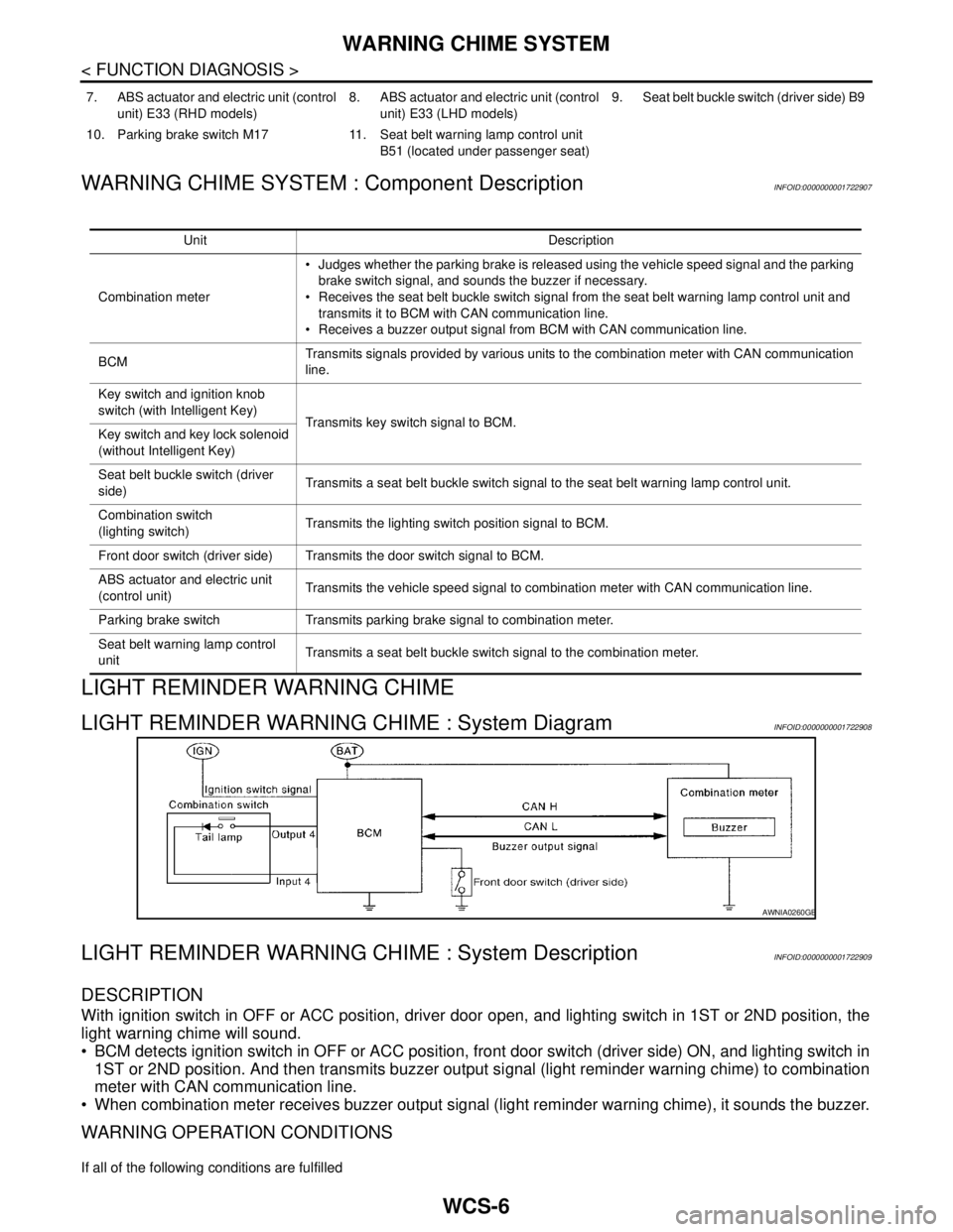
LIGHT REMINDER WARNING CHIME : System DiagramINFOID:0000000001722908
LIGHT REMINDER WARNING CHIME : System DescriptionINFOID:0000000001722909
DESCRIPTION
With ignition switch in OFF or ACC position, driver door open, and lighting switch in 1ST or 2ND position, the
light warning chime will sound.
BCM detects ignition switch in OFF or ACC position, front door switch (driver side) ON, and lighting switch in
1ST or 2ND position. And then transmits buzzer output signal (light reminder warning chime) to combination
meter with CAN communication line.
When combination meter receives buzzer output signal (light reminder warning chime), it sounds the buzzer.
WARNING OPERATION CONDITIONS
If all of the following conditions are fulfilled
7. ABS actuator and electric unit (control
unit) E33 (RHD models)8. ABS actuator and electric unit (control
unit) E33 (LHD models)9. Seat belt buckle switch (driver side) B9
10. Parking brake switch M17 11. Seat belt warning lamp control unit
B51 (located under passenger seat)
Unit Description
Combination meter Judges whether the parking brake is released using the vehicle speed signal and the parking
brake switch signal, and sounds the buzzer if necessary.
Receives the seat belt buckle switch signal from the seat belt warning lamp control unit and
transmits it to BCM with CAN communication line.
Receives a buzzer output signal from BCM with CAN communication line.
BCMTransmits signals provided by various units to the combination meter with CAN communication
line.
Key switch and ignition knob
switch (with Intelligent Key)
Transmits key switch signal to BCM.
Key switch and key lock solenoid
(without Intelligent Key)
Seat belt buckle switch (driver
side)Transmits a seat belt buckle switch signal to the seat belt warning lamp control unit.
Combination switch
(lighting switch)Transmits the lighting switch position signal to BCM.
Front door switch (driver side) Transmits the door switch signal to BCM.
ABS actuator and electric unit
(control unit)Transmits the vehicle speed signal to combination meter with CAN communication line.
Parking brake switch Transmits parking brake signal to combination meter.
Seat belt warning lamp control
unitTransmits a seat belt buckle switch signal to the combination meter.
AWNIA0260GB
Page 5724 of 5883
WCS
WARNING CHIME SYSTEM
WCS-9
< FUNCTION DIAGNOSIS >
C
D
E
F
G
H
I
J
K
L
MB A
O
P
LIGHT REMINDER WARNING CHIME : Component DescriptionINFOID:0000000001722911
SEAT BELT WARNING CHIME
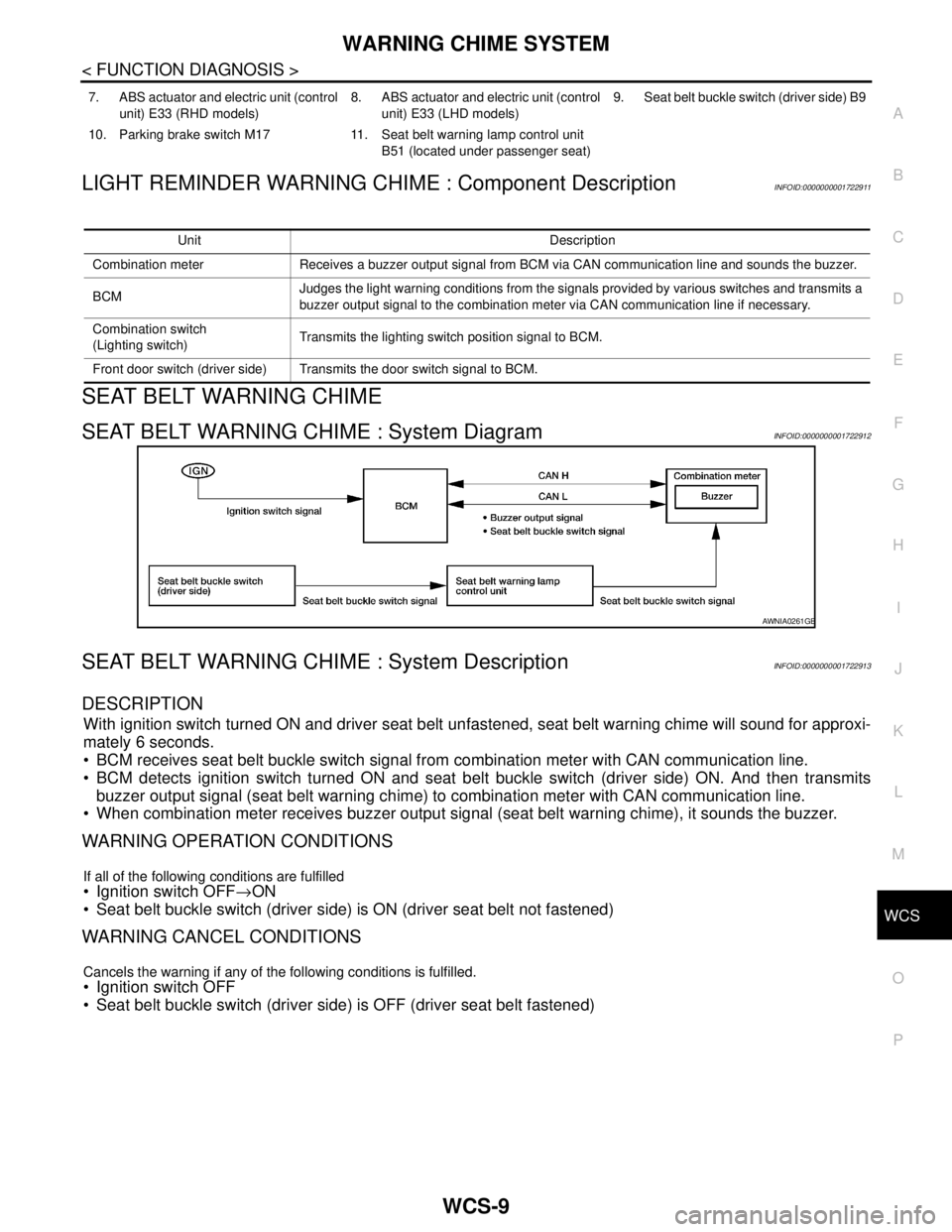
SEAT BELT WARNING CHIME : System DiagramINFOID:0000000001722912
SEAT BELT WARNING CHIME : System DescriptionINFOID:0000000001722913
DESCRIPTION
With ignition switch turned ON and driver seat belt unfastened, seat belt warning chime will sound for approxi-
mately 6 seconds.
BCM receives seat belt buckle switch signal from combination meter with CAN communication line.
BCM detects ignition switch turned ON and seat belt buckle switch (driver side) ON. And then transmits
buzzer output signal (seat belt warning chime) to combination meter with CAN communication line.
When combination meter receives buzzer output signal (seat belt warning chime), it sounds the buzzer.
WARNING OPERATION CONDITIONS
If all of the following conditions are fulfilled
Ignition switch OFF→ON
Seat belt buckle switch (driver side) is ON (driver seat belt not fastened)
WARNING CANCEL CONDITIONS
Cancels the warning if any of the following conditions is fulfilled.
Ignition switch OFF
Seat belt buckle switch (driver side) is OFF (driver seat belt fastened)
7. ABS actuator and electric unit (control
unit) E33 (RHD models)8. ABS actuator and electric unit (control
unit) E33 (LHD models)9. Seat belt buckle switch (driver side) B9
10. Parking brake switch M17 11. Seat belt warning lamp control unit
B51 (located under passenger seat)
Unit Description
Combination meter Receives a buzzer output signal from BCM via CAN communication line and sounds the buzzer.
BCMJudges the light warning conditions from the signals provided by various switches and transmits a
buzzer output signal to the combination meter via CAN communication line if necessary.
Combination switch
(Lighting switch)Transmits the lighting switch position signal to BCM.
Front door switch (driver side) Transmits the door switch signal to BCM.
AWNIA0261GB
Page 5726 of 5883
WCS
WARNING CHIME SYSTEM
WCS-11
< FUNCTION DIAGNOSIS >
C
D
E
F
G
H
I
J
K
L
MB A
O
P
SEAT BELT WARNING CHIME : Component DescriptionINFOID:0000000001722915
KEY WARNING CHIME (WITH INTELLIGENT KEY)
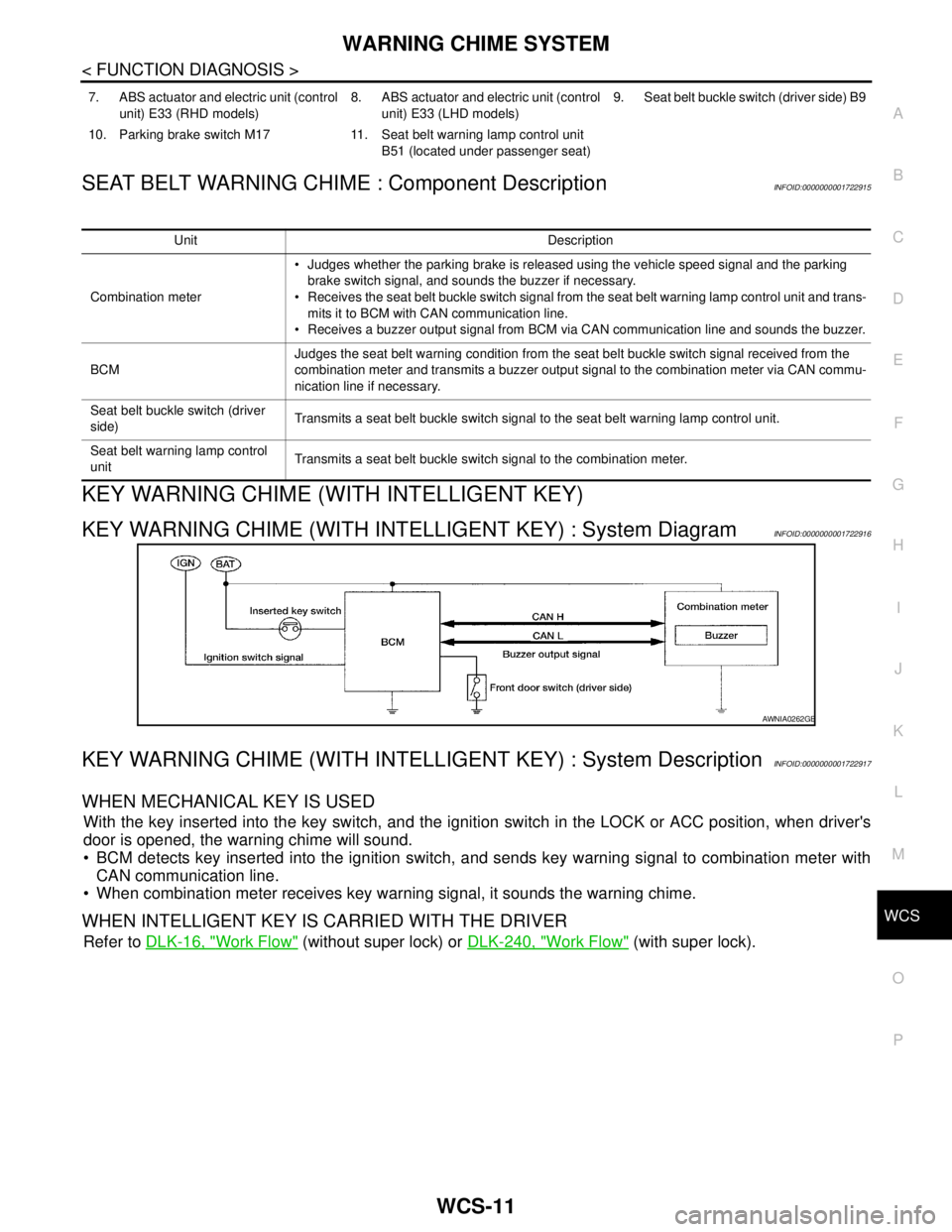
KEY WARNING CHIME (WITH INTELLIGENT KEY) : System DiagramINFOID:0000000001722916
KEY WARNING CHIME (WITH INTELLIGENT KEY) : System DescriptionINFOID:0000000001722917
WHEN MECHANICAL KEY IS USED
With the key inserted into the key switch, and the ignition switch in the LOCK or ACC position, when driver's
door is opened, the warning chime will sound.
BCM detects key inserted into the ignition switch, and sends key warning signal to combination meter with
CAN communication line.
When combination meter receives key warning signal, it sounds the warning chime.
WHEN INTELLIGENT KEY IS CARRIED WITH THE DRIVER
Refer to DLK-16, "Work Flow" (without super lock) or DLK-240, "Work Flow" (with super lock).
7. ABS actuator and electric unit (control
unit) E33 (RHD models)8. ABS actuator and electric unit (control
unit) E33 (LHD models)9. Seat belt buckle switch (driver side) B9
10. Parking brake switch M17 11. Seat belt warning lamp control unit
B51 (located under passenger seat)
Unit Description
Combination meter Judges whether the parking brake is released using the vehicle speed signal and the parking
brake switch signal, and sounds the buzzer if necessary.
Receives the seat belt buckle switch signal from the seat belt warning lamp control unit and trans-
mits it to BCM with CAN communication line.
Receives a buzzer output signal from BCM via CAN communication line and sounds the buzzer.
BCMJudges the seat belt warning condition from the seat belt buckle switch signal received from the
combination meter and transmits a buzzer output signal to the combination meter via CAN commu-
nication line if necessary.
Seat belt buckle switch (driver
side)Transmits a seat belt buckle switch signal to the seat belt warning lamp control unit.
Seat belt warning lamp control
unitTransmits a seat belt buckle switch signal to the combination meter.
AWNIA0262GB
Page 5728 of 5883
WCS
WARNING CHIME SYSTEM
WCS-13
< FUNCTION DIAGNOSIS >
C
D
E
F
G
H
I
J
K
L
MB A
O
P
KEY WARNING CHIME (WITH INTELLIGENT KEY) : Component Description
INFOID:0000000001722919
KEY WARNING CHIME (WITHOUT INTELLIGENT KEY)
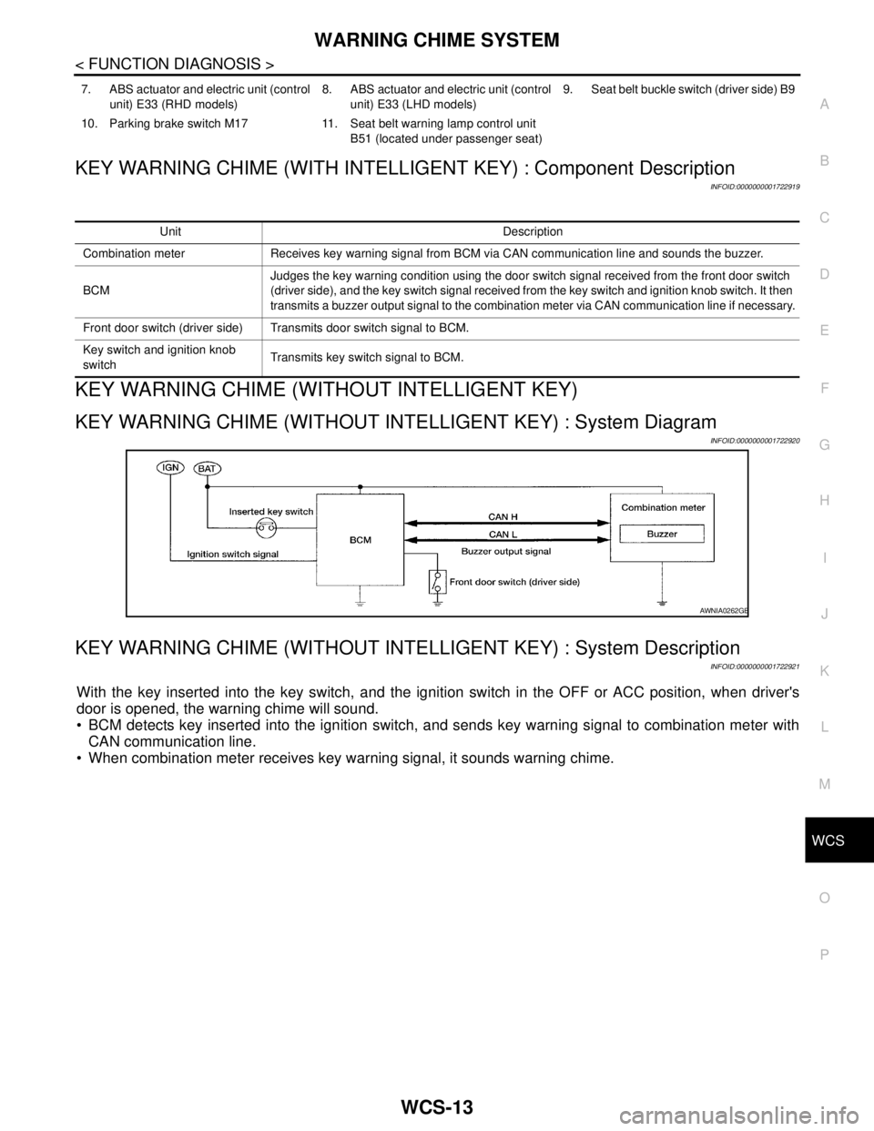
KEY WARNING CHIME (WITHOUT INTELLIGENT KEY) : System Diagram
INFOID:0000000001722920
KEY WARNING CHIME (WITHOUT INTELLIGENT KEY) : System Description
INFOID:0000000001722921
With the key inserted into the key switch, and the ignition switch in the OFF or ACC position, when driver's
door is opened, the warning chime will sound.
BCM detects key inserted into the ignition switch, and sends key warning signal to combination meter with
CAN communication line.
When combination meter receives key warning signal, it sounds warning chime.
7. ABS actuator and electric unit (control
unit) E33 (RHD models)8. ABS actuator and electric unit (control
unit) E33 (LHD models)9. Seat belt buckle switch (driver side) B9
10. Parking brake switch M17 11. Seat belt warning lamp control unit
B51 (located under passenger seat)
Unit Description
Combination meter Receives key warning signal from BCM via CAN communication line and sounds the buzzer.
BCMJudges the key warning condition using the door switch signal received from the front door switch
(driver side), and the key switch signal received from the key switch and ignition knob switch. It then
transmits a buzzer output signal to the combination meter via CAN communication line if necessary.
Front door switch (driver side) Transmits door switch signal to BCM.
Key switch and ignition knob
switchTransmits key switch signal to BCM.
AWNIA0262GB
Page 5730 of 5883
WCS
WARNING CHIME SYSTEM
WCS-15
< FUNCTION DIAGNOSIS >
C
D
E
F
G
H
I
J
K
L
MB A
O
P
KEY WARNING CHIME (WITHOUT INTELLIGENT KEY) : Component Description
INFOID:0000000001722923
PARKING BRAKE RELEASE WARNING CHIME
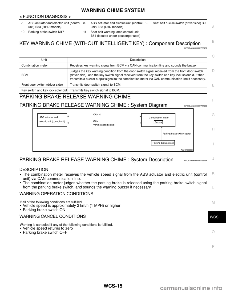
PARKING BRAKE RELEASE WARNING CHIME : System DiagramINFOID:0000000001722963
PARKING BRAKE RELEASE WARNING CHIME : System DescriptionINFOID:0000000001722964
DESCRIPTION
The combination meter receives the vehicle speed signal from the ABS actuator and electric unit (control
unit) via CAN communication line.
The combination meter judges whether the parking brake is released using the parking brake switch signal
from the parking brake switch, and sounds the warning buzzer if necessary.
WARNING OPERATION CONDITIONS
If all of the following conditions are fulfilled Vehicle speed is approximately 2 km/h (1 MPH) or higher
Parking brake switch ON
WARNING CANCEL CONDITIONS
Warning is canceled if any of the following conditions is fulfilled.
Vehicle speed returns to zero
Parking brake switch OFF
7. ABS actuator and electric unit (control
unit) E33 (RHD models)8. ABS actuator and electric unit (control
unit) E33 (LHD models)9. Seat belt buckle switch (driver side) B9
10. Parking brake switch M17 11. Seat belt warning lamp control unit
B51 (located under passenger seat)
Unit Description
Combination meter Receives key warning signal from BCM via CAN communication line and sounds the buzzer.
BCMJudges the key warning condition from the door switch signal received from the front door switch
(driver side), and the key switch signal received from the key switch and key lock solenoid. It then
transmits a buzzer output signal to the combination meter via CAN communication line if necessary.
Front door switch (driver side) Transmits door switch signal to BCM.
Key switch and key lock solenoid Transmits key switch signal to BCM.
AWNIA0263GB