2007 NISSAN TIIDA parking brake
[x] Cancel search: parking brakePage 3175 of 5883
FUEL TANK
FL-15
< ON-VEHICLE REPAIR >
C
D
E
F
G
H
I
J
K
L
MA
FL
N
P O
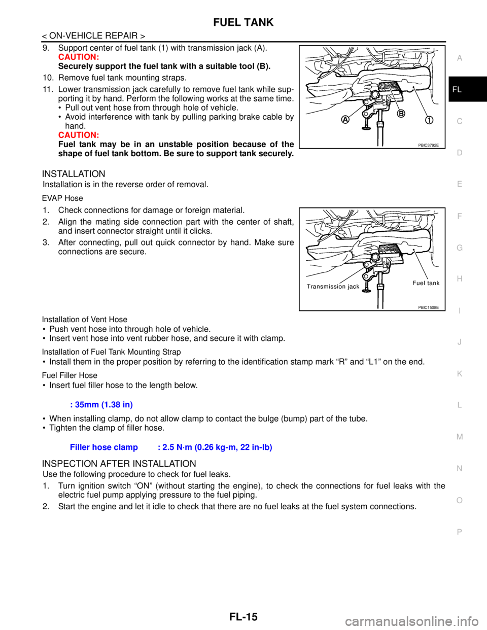
9. Support center of fuel tank (1) with transmission jack (A).
CAUTION:
Securely support the fuel tank with a suitable tool (B).
10. Remove fuel tank mounting straps.
11. Lower transmission jack carefully to remove fuel tank while sup-
porting it by hand. Perform the following works at the same time.
Pull out vent hose from through hole of vehicle.
Avoid interference with tank by pulling parking brake cable by
hand.
CAUTION:
Fuel tank may be in an unstable position because of the
shape of fuel tank bottom. Be sure to support tank securely.
INSTALLATION
Installation is in the reverse order of removal.
EVAP Hose
1. Check connections for damage or foreign material.
2. Align the mating side connection part with the center of shaft,
and insert connector straight until it clicks.
3. After connecting, pull out quick connector by hand. Make sure
connections are secure.
Installation of Vent Hose
Push vent hose into through hole of vehicle.
Insert vent hose into vent rubber hose, and secure it with clamp.
Installation of Fuel Tank Mounting Strap
Install them in the proper position by referring to the identification stamp mark “R” and “L1” on the end.
Fuel Filler Hose
Insert fuel filler hose to the length below.
When installing clamp, do not allow clamp to contact the bulge (bump) part of the tube.
Tighten the clamp of filler hose.
INSPECTION AFTER INSTALLATION
Use the following procedure to check for fuel leaks.
1. Turn ignition switch “ON” (without starting the engine), to check the connections for fuel leaks with the
electric fuel pump applying pressure to the fuel piping.
2. Start the engine and let it idle to check that there are no fuel leaks at the fuel system connections.
PBIC3792E
PBIC1508E
: 35mm (1.38 in)
Filler hose clamp : 2.5 N·m (0.26 kg-m, 22 in-lb)
Page 3208 of 5883
GI-14
< HOW TO USE THIS MANUAL >
HOW TO USE THIS MANUAL
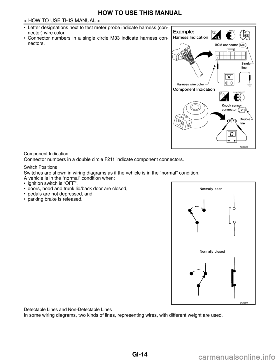
Letter designations next to test meter probe indicate harness (con-
nector) wire color.
Connector numbers in a single circle M33 indicate harness con-
nectors.
Component Indication
Connector numbers in a double circle F211 indicate component connectors.
Switch Positions
Switches are shown in wiring diagrams as if the vehicle is in the “normal” condition.
A vehicle is in the “normal” condition when:
ignition switch is “OFF”,
doors, hood and trunk lid/back door are closed,
pedals are not depressed, and
parking brake is released.
Detectable Lines and Non-Detectable Lines
In some wiring diagrams, two kinds of lines, representing wires, with different weight are used.
AGI070
SGI860
Page 3218 of 5883
GI-24
< HOW TO USE THIS MANUAL >
HOW TO READ WIRING DIAGRAMS
ignition switch is “OFF”,
doors, hood and trunk lid/back door are closed,
pedals are not depressed, and
parking brake is released.
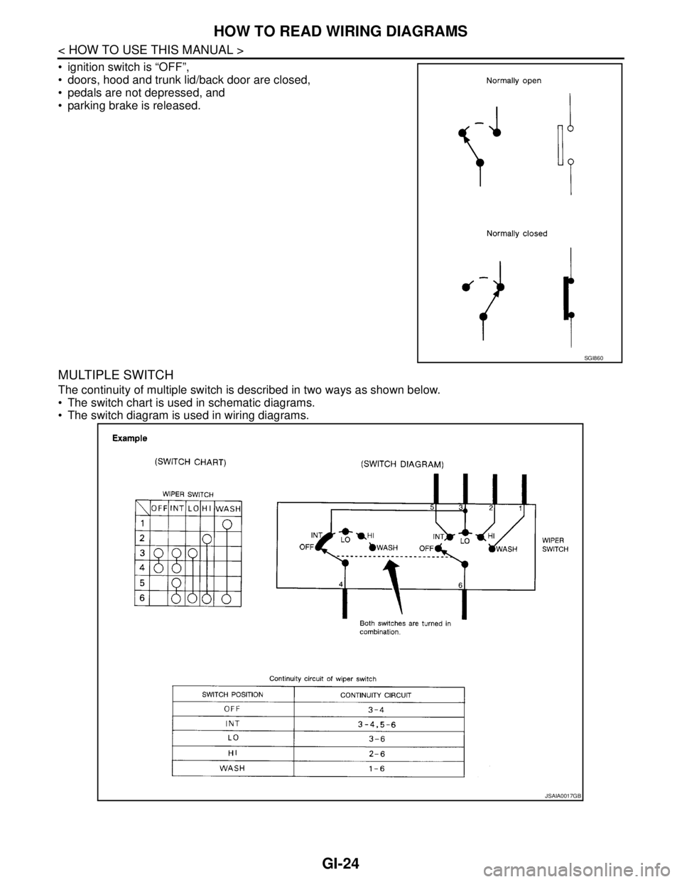
MULTIPLE SWITCH
The continuity of multiple switch is described in two ways as shown below.
The switch chart is used in schematic diagrams.
The switch diagram is used in wiring diagrams.
SGI860
JSAIA0017GB
Page 4213 of 5883
![NISSAN TIIDA 2007 Service Repair Manual LU-6
< ON-VEHICLE MAINTENANCE >[HR16DE]
ENGINE OIL
ON-VEHICLE MAINTENANCE
ENGINE OIL
InspectionINFOID:0000000001381527
ENGINE OIL LEVEL
NOTE:
Before starting engine, put vehicle horizontally and check NISSAN TIIDA 2007 Service Repair Manual LU-6
< ON-VEHICLE MAINTENANCE >[HR16DE]
ENGINE OIL
ON-VEHICLE MAINTENANCE
ENGINE OIL
InspectionINFOID:0000000001381527
ENGINE OIL LEVEL
NOTE:
Before starting engine, put vehicle horizontally and check](/manual-img/5/57395/w960_57395-4212.png)
LU-6
< ON-VEHICLE MAINTENANCE >[HR16DE]
ENGINE OIL
ON-VEHICLE MAINTENANCE
ENGINE OIL
InspectionINFOID:0000000001381527
ENGINE OIL LEVEL
NOTE:
Before starting engine, put vehicle horizontally and check the engine oil level. If engine is already started, stop
it and allow 10 minutes before checking.
1. Pull out oil level gauge and wipe it clean.
2. Insert oil level gauge and make sure the engine oil level is within
the range (A) shown in the figure.
3. If it is out of range, adjust it.
ENGINE OIL APPEARANCE
Check engine oil for white turbidity or heavy contamination.
If engine oil becomes turbid and white, it is highly probable that it is contaminated with engine coolant.
Repair or replace damaged parts.
ENGINE OIL LEAKAGE
Check for engine oil leakage around the following area.
Oil pan (upper and lower)
Oil pan drain plug
Oil pressure switch
Oil level sensor
Oil filter
Intake valve timing control solenoid valve
Front cover
Mating surface between cylinder head and camshaft bracket
Mating surface between cylinder block and cylinder head
Mating surface between cylinder head and rocker cover
Crankshaft oil seals (front and rear)
Oil filter (for intake valve timing control)
OIL PRESSURE CHECK
WARNING:
Be careful not to get burned, as engine oil may be hot.
When checking engine oil pressure, shift position should be “Neutral”, and apply parking brake
securely.
1. Check engine oil level. Refer to LU-6, "
Inspection".
JPBIA0554ZZ
Page 4222 of 5883
![NISSAN TIIDA 2007 Service Repair Manual ENGINE OIL
LU-15
< ON-VEHICLE MAINTENANCE >[MR18DE]
C
D
E
F
G
H
I
J
K
L
MA
LU
N
P O
ON-VEHICLE MAINTENANCE
ENGINE OIL
InspectionINFOID:0000000001337827
ENGINE OIL LEVEL
NOTE:
Before starting engine, p NISSAN TIIDA 2007 Service Repair Manual ENGINE OIL
LU-15
< ON-VEHICLE MAINTENANCE >[MR18DE]
C
D
E
F
G
H
I
J
K
L
MA
LU
N
P O
ON-VEHICLE MAINTENANCE
ENGINE OIL
InspectionINFOID:0000000001337827
ENGINE OIL LEVEL
NOTE:
Before starting engine, p](/manual-img/5/57395/w960_57395-4221.png)
ENGINE OIL
LU-15
< ON-VEHICLE MAINTENANCE >[MR18DE]
C
D
E
F
G
H
I
J
K
L
MA
LU
N
P O
ON-VEHICLE MAINTENANCE
ENGINE OIL
InspectionINFOID:0000000001337827
ENGINE OIL LEVEL
NOTE:
Before starting engine, park vehicle on a level surface and check the engine oil level. If engine is already
started, stop it and allow 10 minutes before checking.
1. Pull out oil level gauge and wipe it clean.
2. Insert oil level gauge and make sure the engine oil level is within
the range (A) as shown.
3. If it is out of range, adjust it.
ENGINE OIL APPEARANCE
Check engine oil for white turbidity or heavy contamination.
If engine oil becomes turbid and white, it is highly probable that it is contaminated with engine coolant.
Repair or replace damaged parts.
ENGINE OIL LEAKAGE
Check for engine oil leakage around the following areas:
Oil pan (upper and lower)
Oil pan drain plug
Oil pressure switch
Oil filter
Intake valve timing control solenoid valve
Front cover
Mating surface between cylinder block and cylinder head
Mating surface between cylinder head and rocker cover
Crankshaft oil seals (front and rear)
Oil filter (for intake valve timing control)
OIL PRESSURE CHECK
WARNING:
Be careful not to burn yourself, as engine oil may be hot.
For engine oil pressure check the transaxle should be in “Neutral position”, and apply the parking
brake securely.
1. Disconnect harness connector at oil pressure switch (1), and
remove oil pressure switch using a suitable tool.
Oil pan (lower) (2)
⇐ Front
WBIA0776E
PBIC3310E
Page 4246 of 5883
MA-6
< ON-VEHICLE MAINTENANCE >
GENERAL MAINTENANCE
ON-VEHICLE MAINTENANCE
GENERAL MAINTENANCE
General MaintenanceINFOID:0000000001277597
General maintenance includes those items which should be checked during the normal day-to-day operation
of the vehicle. They are essential if the vehicle is to continue operating properly. The owners can perform the
checks and inspections themselves or they can have their NISSAN dealers do them for a nominal charge.
OUTSIDE THE VEHICLE
The maintenance items listed here should be performed from time to time, unless otherwise specified.
INSIDE THE VEHICLE
The maintenance items listed here should be checked on a regular basis, such as when performing periodic maintenance, cleaning the vehicle,
etc.
UNDER THE HOOD AND VEHICLE
The maintenance items listed here should be checked periodically e.g. each time you check the engine oil or refuel.
Item Reference page
TiresCheck the pressure with a gauge periodically when at a service station, including
the spare, and adjust to the specified pressure if necessary. Check carefully for
damage, cuts or excessive wear.WT-7, "
Tire"
Windshield wiper
bladesCheck for cracks or wear if not functioning correctly. —
Doors and engine
hoodCheck that all doors, the engine hood, the trunk lid and back door operate prop-
erly. Also ensure that all latches lock securely. Lubricate if necessary. Make sure
that the secondary latch keeps the hood from opening when the primary latch is
released.
When driving in areas using road salt or other corrosive materials, check for lu-
brication frequently.MA-57, "
Lubricating
Locks, Hinges and Hood
Latch"
Tire rotationTires should be rotated every 10,000 km (6,000 miles) for 2WD models and every
5,000 km (3,000 miles) for 4WD models.MA-53
Item Reference page
LampsMake sure that the headlamps, stop lamps, tail lamps, turn signal lamps, and oth-
er lamps are all operating properly and installed securely. Also check headlamp
aim.—
Warning lamps and
chimesMake sure that all warning lamps and buzzers/chimes are operating properly. —
Steering wheelCheck that it has the specified play.
Check for changes in the steering conditions, such as excessive free play, hard
steering or strange noises.
Free play: Less than 35 mm (1.38 in)—
Seat beltsCheck that all parts of the seat belt system (e.g. buckles, anchors, adjusters and
retractors) operate properly and smoothly, and are installed securely. Check the
belt webbing for cuts, fraying, wear or damage.MA-57
Item Reference page
Windshield washer
fluidCheck that there is adequate fluid in the tank. —
Engine coolant levelCheck the coolant level when the engine is cold.MA-23
(HR)
MA-31
(MR)
MA-42
(K9K)
Engine oil levelCheck the level after parking the vehicle on a level spot and turning off the en-
gine.LU-6
(HR)
LU-15
(MR)
LU-26
(K9K)
Brake and clutch fluid
levelsMake sure that the brake and clutch fluid levels are between the “MAX” and “MIN”
lines on the reservoir.MA-50
,
MA-54
BatteryCheck the fluid level in each cell. It should be between the “MAX” and “MIN” lines. —
Page 4248 of 5883
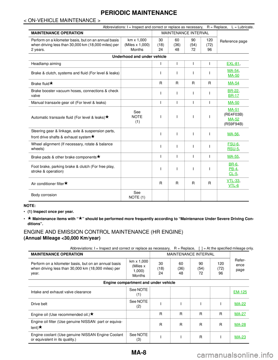
MA-8
< ON-VEHICLE MAINTENANCE >
PERIODIC MAINTENANCE
Abbreviations: I = Inspect and correct or replace as necessary, R = Replace, L = Lubricate.
NOTE:
(1) Inspect once per year.
Maintenance items with “ ” should be performed more frequently according to “Maintenance Under Severe Driving Con-
ditions”.
ENGINE AND EMISSION CONTROL MAINTENANCE (HR ENGINE)
(Annual Mileage <30,000 Km/year)
Abbreviations: I = Inspect and correct or replace as necessary, R = Replace,[ ] = At the specified mileage only.
MAINTENANCE OPERATIONMAINTENANCE INTERVAL
Reference page Perform on a kilometer basis, but on an annual basis
when driving less than 30,000 km (18,000 miles) per
2 years.km x 1,000
(Miles x 1,000)
Months30
(18)
2460
(36)
4890
(54)
72120
(72)
96
Underhood and under vehicle
Headlamp aiming I I I IEXL-81
,
Brake & clutch, systems and fluid (For level & leaks) I I I IMA-54
,
MA-50
Brake fluidRRRRMA-54
Brake booster vacuum hoses, connections & check
valveIIIIBR-22,
BR-17
Manual transaxle gear oil (For level & leaks) I I I IMA-50
Automatic transaxle fluid (For level & leaks)See
NOTE
(1)IIIIMA-51(RE4F03B)
MA-52
(RS9F94B)
Steering gear & linkage, axle & suspension parts,
front drive shafts & exhaust systemIIIIMA-56
,
Wheel alignment (If necessary, rotate & balance
wheels)IIIIFSU-6
,
RSU-5
,
Brake pads & other brake componentsIIIIMA-55
,
Foot brake, parking brake & clutch (For free play,
stroke & operation)IIIIBR-6
,
PB-4
,
CL-5
,
Air conditioner filterRRRRVTL-33
,
VTL-6
Body corrosionSee
NOTE (1)
MAINTENANCE OPERATIONMAINTENANCE INTERVAL
Refer-
ence
page Perform on a kilometer basis, but on an annual basis
when driving less than 30,000 km (18,000 miles) per
year.km x 1,000
(Miles x
1,000)
Months30
(18)
2460
(36)
4890
(54)
72120
(72)
96
Engine compartment and under vehicle
Intake and exhaust valve clearanceSee NOTE
(1)EM-125
Drive beltSee NOTE
(2)IIIIMA-22
Engine oil (Use recommended oil.)R RRRMA-27
Engine oil filter (Use genuine NISSAN part or equiva-
lent)R RRRMA-28
Engine coolant (Use genuine NISSAN Engine Coolant
or equivalent in its quality.)See NOTE
(3)IIRIMA-23
Page 4249 of 5883
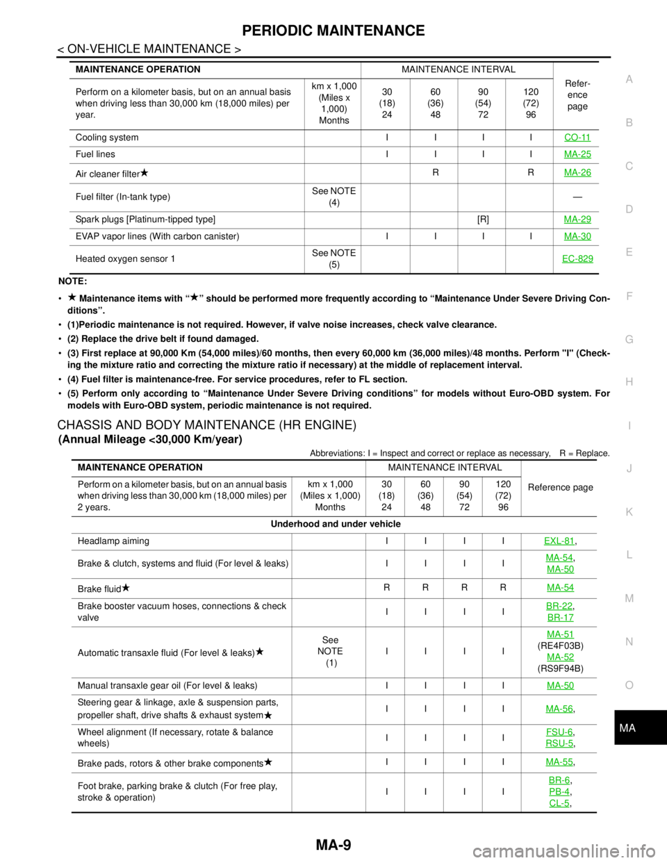
PERIODIC MAINTENANCE
MA-9
< ON-VEHICLE MAINTENANCE >
C
D
E
F
G
H
I
J
K
L
MB
MAN
OA
NOTE:
Maintenance items with “ ” should be performed more frequently according to “Maintenance Under Severe Driving Con-
ditions”.
(1)Periodic maintenance is not required. However, if valve noise increases, check valve clearance.
(2) Replace the drive belt if found damaged.
(3) First replace at 90,000 Km (54,000 miles)/60 months, then every 60,000 km (36,000 miles)/48 months. Perform "I" (Check-
ing the mixture ratio and correcting the mixture ratio if necessary) at the middle of replacement interval.
(4) Fuel filter is maintenance-free. For service procedures, refer to FL section.
(5) Perform only according to “Maintenance Under Severe Driving conditions” for models without Euro-OBD system. For
models with Euro-OBD system, periodic maintenance is not required.
CHASSIS AND BODY MAINTENANCE (HR ENGINE)
(Annual Mileage <30,000 Km/year)
Abbreviations: I = Inspect and correct or replace as necessary, R = Replace.
Cooling system I I I ICO-11
Fuel lines I I I IMA-25
Air cleaner filterRRMA-26
Fuel filter (In-tank type)See NOTE
(4)—
Spark plugs [Platinum-tipped type] [R]MA-29
EVAP vapor lines (With carbon canister) I I I IMA-30
Heated oxygen sensor 1See NOTE
(5)EC-829
MAINTENANCE OPERATIONMAINTENANCE INTERVAL
Refer-
ence
page Perform on a kilometer basis, but on an annual basis
when driving less than 30,000 km (18,000 miles) per
year.km x 1,000
(Miles x
1,000)
Months30
(18)
2460
(36)
4890
(54)
72120
(72)
96
MAINTENANCE OPERATIONMAINTENANCE INTERVAL
Reference page Perform on a kilometer basis, but on an annual basis
when driving less than 30,000 km (18,000 miles) per
2 years.km x 1,000
(Miles x 1,000)
Months30
(18)
2460
(36)
4890
(54)
72120
(72)
96
Underhood and under vehicle
Headlamp aiming IIIIEXL-81
,
Brake & clutch, systems and fluid (For level & leaks) IIIIMA-54
,
MA-50
Brake fluidRRRRMA-54
Brake booster vacuum hoses, connections & check
valveIIIIBR-22,
BR-17
Automatic transaxle fluid (For level & leaks)See
NOTE
(1)IIIIMA-51(RE4F03B)
MA-52
(RS9F94B)
Manual transaxle gear oil (For level & leaks) IIIIMA-50
Steering gear & linkage, axle & suspension parts,
propeller shaft, drive shafts & exhaust systemIIIIMA-56,
Wheel alignment (If necessary, rotate & balance
wheels)IIIIFSU-6
,
RSU-5
,
Brake pads, rotors & other brake componentsIIIIMA-55
,
Foot brake, parking brake & clutch (For free play,
stroke & operation)IIIIBR-6
,
PB-4
,
CL-5
,