2007 NISSAN TIIDA oil
[x] Cancel search: oilPage 4431 of 5883
![NISSAN TIIDA 2007 Service Repair Manual PCS
IPDM E/R (INTELLIGENT POWER DISTRIBUTION MODULE ENGINE ROOM)
PCS-17
< ECU DIAGNOSIS >[IPDM E/R]
C
D
E
F
G
H
I
J
K
L B A
O
P N
ECU DIAGNOSIS
IPDM E/R (INTELLIGENT POWER DISTRIBUTION MODULE ENGINE
R NISSAN TIIDA 2007 Service Repair Manual PCS
IPDM E/R (INTELLIGENT POWER DISTRIBUTION MODULE ENGINE ROOM)
PCS-17
< ECU DIAGNOSIS >[IPDM E/R]
C
D
E
F
G
H
I
J
K
L B A
O
P N
ECU DIAGNOSIS
IPDM E/R (INTELLIGENT POWER DISTRIBUTION MODULE ENGINE
R](/manual-img/5/57395/w960_57395-4430.png)
PCS
IPDM E/R (INTELLIGENT POWER DISTRIBUTION MODULE ENGINE ROOM)
PCS-17
< ECU DIAGNOSIS >[IPDM E/R]
C
D
E
F
G
H
I
J
K
L B A
O
P N
ECU DIAGNOSIS
IPDM E/R (INTELLIGENT POWER DISTRIBUTION MODULE ENGINE
ROOM)
Reference ValueINFOID:0000000001697595
VALUES ON THE DIAGNOSIS TOOL
Monitor Item Condition Value/Status
MOTOR FAN REQ Engine idle speedChanges depending on engine
coolant temperature, air conditioner
operation status, vehicle speed,
etc.0 - 100 %
A/C COMP REQA/C switch OFF OFF
A/C switch ON ON
TA I L & C L R R E QLighting switch OFF OFF
Lighting switch 1ST, 2ND, HI or AUTO (Light is illuminated) ON
HL LO REQLighting switch OFF OFF
Lighting switch 2ND HI or AUTO (Light is illuminated) ON
HL HI REQLighting switch OFF OFF
Lighting switch HI ON
FR FOG REQLighting switch 2ND or AUTO (Light
is illuminated)Front fog lamp switch OFF OFF
Front fog lamp switch ON
Daytime light activated ON
HL WASHER REQNOTE:
This item is displayed, but cannot be monitored.OFF
FR WIP REQ Ignition switch ONFront wiper switch OFF STOP
Front wiper switch INT 1LOW
Front wiper switch LO LOW
Front wiper switch HI HI
WIP AUTO STOP Ignition switch ONFront wiper stop position STOP P
Any position other than front wiper
stop positionACT P
WIP PROT Ignition switch ONFront wiper operates normally OFF
Front wiper stops at fail-safe opera-
tionBLOCK
ST RLY REQIgnition switch OFF or ACC OFF
Ignition switch START ON
IGN RLYIgnition switch OFF or ACC OFF
Ignition switch ON ON
RR DEF REQRear defogger switch OFF OFF
Rear defogger switch ON ON
OIL P SWIgnition switch OFF, ACC or engine running OPEN
Ignition switch ON CLOSE
DTRL REQNOTE:
This item is displayed, but cannot be monitored.OFF
HOOD SWNOTE:
This item is displayed, but cannot be monitored.OFF
Page 4435 of 5883
![NISSAN TIIDA 2007 Service Repair Manual PCS
IPDM E/R (INTELLIGENT POWER DISTRIBUTION MODULE ENGINE ROOM)
PCS-21
< ECU DIAGNOSIS >[IPDM E/R]
C
D
E
F
G
H
I
J
K
L B A
O
P N
29 PTail lamp relay (park-
ing lamps)Output — Lighting switch in 2nd NISSAN TIIDA 2007 Service Repair Manual PCS
IPDM E/R (INTELLIGENT POWER DISTRIBUTION MODULE ENGINE ROOM)
PCS-21
< ECU DIAGNOSIS >[IPDM E/R]
C
D
E
F
G
H
I
J
K
L B A
O
P N
29 PTail lamp relay (park-
ing lamps)Output — Lighting switch in 2nd](/manual-img/5/57395/w960_57395-4434.png)
PCS
IPDM E/R (INTELLIGENT POWER DISTRIBUTION MODULE ENGINE ROOM)
PCS-21
< ECU DIAGNOSIS >[IPDM E/R]
C
D
E
F
G
H
I
J
K
L B A
O
P N
29 PTail lamp relay (park-
ing lamps)Output — Lighting switch in 2nd position Battery voltage
30 R Fuse 54 Output —Ignition switch ON or START Battery voltage
Ignition switch OFF or ACC 0V
31 O Fuse 55 Output —Ignition switch ON or START Battery voltage
Ignition switch OFF or ACC 0V
32 LWiper high speed sig-
nalOutputON or
STARTWiper switchOFF, LO, INT 0V
HI Battery voltage
33 YWiper low speed sig-
nalOutputON or
STARTWiper switchOFF 0V
LO or INT Battery voltage
35 BRStarter relay (inhibit
switch)InputON or
STARTSelector lever in "P" or "N"
(CVT or A/T) or clutch pedal
depressed (M/T)Battery voltage
Selector lever any other posi-
tion (CVT or A/T) or clutch
pedal released (M/T)0V
36 BR Fuel pump relay Output —Ignition switch ON or START Battery voltage
Ignition switch OFF or ACC 0V
37 G Oil pressure switch InputON or
STARTEngine running and oil pres-
sure within specificationBattery voltage
Engine not running or oil pres-
sure below specification0V
38 R Wiper auto stop signal InputON or
STARTWipers not in park position Battery voltage
Wipers in park position 0V
39 B Ground Input — — 0V
40 P CAN-L — ON — —
41 L CAN-H — ON — —
46 YThrottle control motor
relay controlInput —Ignition switch ON or START 0V
Ignition switch OFF or ACC Battery voltage
47 GRFuel pump relay con-
trolInput —Ignition switch ON or START 0V
Ignition switch OFF or ACC Battery voltage
50 V Front fog lamp (LH)Output ON or
STARTLighting
switch must
be in the 2ND
position
(LOW beam
is ON) and
the front fog
lamp switchOFF 0V
ON Battery voltage
51 W Front fog lamp (RH) OutputON or
STARTLighting
switch must
be in the 2ND
position
(LOW beam
is ON) and
the front fog
lamp switchOFF 0V
ON Battery voltage
52 LLH Low beam head-
lampOutput — Lighting switch in 2nd position Battery voltage Te r m i n a lWire
colorSignal name
Signal
input/
outputMeasuring condition
Reference value
(Approx.) Ignition
switchOperation or condition
Page 4441 of 5883
![NISSAN TIIDA 2007 Service Repair Manual PCS
IPDM E/R (INTELLIGENT POWER DISTRIBUTION MODULE ENGINE ROOM)
PCS-27
< ECU DIAGNOSIS >[IPDM E/R]
C
D
E
F
G
H
I
J
K
L B A
O
P N If No CAN Communication Is Available With BCM
IGNITION RELAY MALFUNCTI NISSAN TIIDA 2007 Service Repair Manual PCS
IPDM E/R (INTELLIGENT POWER DISTRIBUTION MODULE ENGINE ROOM)
PCS-27
< ECU DIAGNOSIS >[IPDM E/R]
C
D
E
F
G
H
I
J
K
L B A
O
P N If No CAN Communication Is Available With BCM
IGNITION RELAY MALFUNCTI](/manual-img/5/57395/w960_57395-4440.png)
PCS
IPDM E/R (INTELLIGENT POWER DISTRIBUTION MODULE ENGINE ROOM)
PCS-27
< ECU DIAGNOSIS >[IPDM E/R]
C
D
E
F
G
H
I
J
K
L B A
O
P N If No CAN Communication Is Available With BCM
IGNITION RELAY MALFUNCTION DETECTION FUNCTION
IPDM E/R monitors the voltage at the contact circuit and excitation coil circuit of the ignition relay inside it.
IPDM E/R judges the ignition relay error if the voltage differs between the contact circuit and the excitation
coil circuit.
If the ignition relay cannot turn OFF due to contact seizure, it activates the tail lamp relay for 10 minutes to
alert the user to the ignition relay malfunction when the ignition switch is turned OFF.
NOTE:
The tail lamp turns OFF when the ignition switch is turned ON.
FRONT WIPER CONTROL
IPDM E/R detects front wiper stop position by a front wiper auto stop signal.
When a front wiper auto stop signal is in the conditions listed below, IPDM E/R stops power supply to wiper
after repeating a front wiper 10 second activation and 20 second stop five times.
NOTE:
This operation status can be confirmed on the IPDM E/R “DATA MONITOR” that displays “Block” for the item
“WIP PROT” while the wiper is stopped.
STARTER MOTOR PROTECTION FUNCTION
IPDM E/R turns OFF the starter control relay to protect the starter motor when the starter control relay remains
active for 90 seconds.
Control part Fail-safe in operation
Cooling fan Turns ON the cooling fan relay when the ignition switch is turned ON
Turns OFF the cooling fan relay when the ignition switch is turned OFF
Control part Fail-safe in operation
Headlamp Turns ON the headlamp low relay when the ignition switch is turned ON
Turns OFF the headlamp low relay when the ignition switch is turned OFF
Headlamp high relay OFF
Parking lamps
License plate lamps
Tail lamps Turns ON the tail lamp relay when the ignition switch is turned ON
Turns OFF the tail lamp relay when the ignition switch is turned OFF
Front wiper The status just before activation of fail-safe control is maintained until the ignition
switch is turned OFF while the front wiper is operating at LO or HI speed.
The wiper is operated at LO speed until the ignition switch is turned OFF if the fail-
safe control is activated while the front wiper is set in the INT mode and the front wiper
motor is operating.
Rear window defogger Rear window defogger relay OFF
A/C compressor A/C relay OFF
Front fog lamps Front fog lamp relay OFF
Ignition switch Ignition relay Tail lamp relay
ON ON —
OFF OFF —
Ignition switch Front wiper switch Auto stop signal
ONOFFFront wiper stop position signal cannot be
input 10 seconds.
ON The signal does not change for 10 seconds.
Page 4530 of 5883

PRECAUTIONS
RAX-3
< PRECAUTION >
C
E
F
G
H
I
J
K
L
MA
B
RAX
N
O
P
PRECAUTION
PRECAUTIONS
Precaution for Supplemental Restraint System (SRS) "AIR BAG" and "SEAT BELT
PRE-TENSIONER"
INFOID:0000000001724594
The Supplemental Restraint System such as “AIR BAG” and “SEAT BELT PRE-TENSIONER”, used along
with a front seat belt, helps to reduce the risk or severity of injury to the driver and front passenger for certain
types of collision. Information necessary to service the system safely is included in the SR and SB section of
this Service Manual.
WARNING:
• To avoid rendering the SRS inoperative, which could increase the risk of personal injury or death in
the event of a collision which would result in air bag inflation, all maintenance must be performed by
an authorized NISSAN/INFINITI dealer.
Improper maintenance, including incorrect removal and installation of the SRS, can lead to personal
injury caused by unintentional activation of the system. For removal of Spiral Cable and Air Bag
Module, see the SR section.
Do not use electrical test equipment on any circuit related to the SRS unless instructed to in this
Service Manual. SRS wiring harnesses can be identified by yellow and/or orange harnesses or har-
ness connectors.
PrecautionINFOID:0000000001724595
When installing each rubber part, final tightening must be car-
ried out under unladen condition* with tires on ground.
*: Fuel, radiator coolant and engine oil full. Spare tire, jack,
hand tools and mats in designated positions.
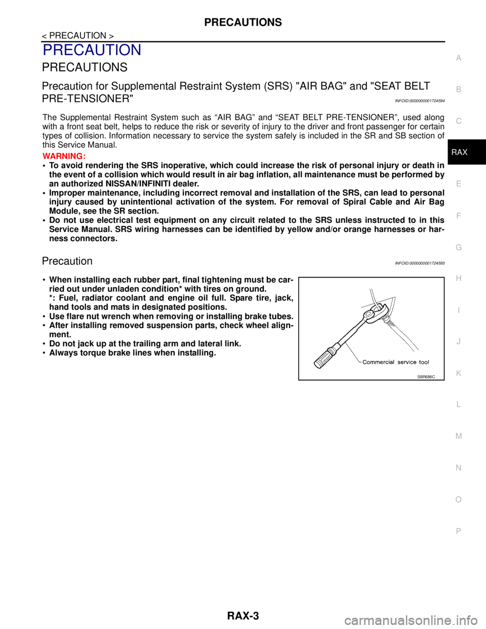
Use flare nut wrench when removing or installing brake tubes.
After installing removed suspension parts, check wheel align-
ment.
Do not jack up at the trailing arm and lateral link.
Always torque brake lines when installing.
SBR686C
Page 4573 of 5883

RSU-1
SUSPENSION
C
D
F
G
H
I
J
K
L
M
SECTION RSU
A
B
RSU
N
O
PCONTENTS
REAR SUSPENSION
SYMPTOM DIAGNOSIS ...............................2
NOISE, VIBRATION AND HARSHNESS
(NVH) TROUBLESHOOTING .............................
2
NVH Troubleshooting Chart ......................................2
PRECAUTION ...............................................3
PRECAUTIONS ...................................................3
Precaution for Supplemental Restraint System
(SRS) "AIR BAG" and "SEAT BELT PRE-TEN-
SIONER" ...................................................................
3
Precaution for Rear Suspension ...............................3
PREPARATION ............................................4
PREPARATION ...................................................4
Commercial Service Tool ..........................................4
ON-VEHICLE MAINTENANCE .....................5
REAR SUSPENSION ASSEMBLY .....................5
On-Vehicle Inspection and Service ..........................5
Wheel Alignment ......................................................5
Component ...............................................................7
ON-VEHICLE REPAIR ..................................8
SHOCK ABSORBER .........................................8
Removal and Installation ..........................................8
COIL SPRING ...................................................10
Removal and Installation .........................................10
REAR SUSPENSION BEAM ............................11
Removal and Installation .........................................11
SERVICE DATA AND SPECIFICATIONS
(SDS) ............................................................
12
SERVICE DATA AND SPECIFICATIONS
(SDS) .................................................................
12
Wheel Alignment (Unladen*) ...................................12
Wheelarch Height (Unladen*) ..................................12
Page 4575 of 5883

PRECAUTIONS
RSU-3
< PRECAUTION >
C
D
F
G
H
I
J
K
L
MA
B
RSU
N
O
P
PRECAUTION
PRECAUTIONS
Precaution for Supplemental Restraint System (SRS) "AIR BAG" and "SEAT BELT
PRE-TENSIONER"
INFOID:0000000001724583
The Supplemental Restraint System such as “AIR BAG” and “SEAT BELT PRE-TENSIONER”, used along
with a front seat belt, helps to reduce the risk or severity of injury to the driver and front passenger for certain
types of collision. This system includes seat belt switch inputs and dual stage front air bag modules. The SRS
system uses the seat belt switches to determine the front air bag deployment, and may only deploy one front
air bag, depending on the severity of a collision and whether the front occupants are belted or unbelted.
Information necessary to service the system safely is included in the SRS and SB section of this Service Man-
ual.
WARNING:
• To avoid rendering the SRS inoperative, which could increase the risk of personal injury or death in
the event of a collision which would result in air bag inflation, all maintenance must be performed by
an authorized NISSAN/INFINITI dealer.
Improper maintenance, including incorrect removal and installation of the SRS, can lead to personal
injury caused by unintentional activation of the system. For removal of Spiral Cable and Air Bag
Module, see the SRS section.
Do not use electrical test equipment on any circuit related to the SRS unless instructed to in this
Service Manual. SRS wiring harnesses can be identified by yellow and/or orange harnesses or har-
ness connectors.
Precaution for Rear SuspensionINFOID:0000000001724584
When installing the rubber bushings, the final tightening must be done under unladen condition and with the
tires on level ground. Oil will shorten the life of the rubber bushings, so wipe off any spilled oil immediately.
Unladen condition means the fuel tank, engine coolant and lubricants are at the full specification. The spare
tire, jack, hand tools, and mats are in their designated positions.
After installing suspension components, check the wheel alignment.
Caulking nuts are not reusable. Always use new caulking nuts for installation. New caulking nuts are pre-
oiled, do not apply any additional lubrication.
Page 4577 of 5883

REAR SUSPENSION ASSEMBLY
RSU-5
< ON-VEHICLE MAINTENANCE >
C
D
F
G
H
I
J
K
L
MA
B
RSU
N
O
P
ON-VEHICLE MAINTENANCE
REAR SUSPENSION ASSEMBLY
On-Vehicle Inspection and ServiceINFOID:0000000001724575
Make sure the mounting conditions (looseness, backlash) of each component and component conditions
(wear, damage) are within specifications.
SHOCK ABSORBER INSPECTION
Check shock absorber for oil leakage, damage and replace it if necessary.
Wheel AlignmentINFOID:0000000001724576
DESCRIPTION
Measure wheel alignment under unladen conditions.
NOTE:
“Unladen conditions” means that fuel, engine coolant, and lubricant are full. Spare tire, jack, hand tools and
mats are in designated positions.
PRELIMINARY
Check the following:
1. Tires for improper air pressure and wear.
2. Road wheels for runout. Refer to WT-5, "
Inspection" .
3. Wheel bearing axial end play. Refer to RAX-5, "
On-Vehicle Inspection and Service" .
4. Shock absorber operation.
5. Each mounting part of suspension for looseness and deformation.
6. Rear suspension beam for cracks, deformation, and other damage.
7. Vehicle height (posture).
GENERAL INFORMATION AND RECOMMENDATIONS
1. A Four-Wheel Thrust Alignment should be performed.
This type of alignment is recommended for any NISSAN vehicle.
The four-wheel “thrust” process helps ensure that the vehicle is properly aligned and the steering wheel
is centered.
The alignment machine itself should be capable of accepting any NISSAN vehicle.
The alignment machine should be checked to ensure that it is level.
2. Make sure the alignment machine is properly calibrated.
Your alignment machine should be regularly calibrated in order to give correct information.
Check with the manufacturer of your specific alignment machine for their recommended Service/Cali-
bration Schedule.
THE ALIGNMENT PROCESS
IMPORTANT: Use only the alignment specifications listed in this Service Manual. Refer to RSU-5, "Wheel
Alignment" .
1. When displaying the alignment settings, many alignment machines use “indicators”: (Green/red, plus or
minus, Go/No Go). Do NOT use these indicators.
The alignment specifications programmed into your alignment machine that operate these indicators
may not be correct.
This may result in an ERROR.
2. Some newer alignment machines are equipped with an optional “Rolling Compensation” method to “com-
pensate” the sensors (alignment targets or head units). Do NOT use this “Rolling Compensation”
method.
Use the “Jacking Compensation” method. After installing the alignment targets or head units, raise the
vehicle and rotate the wheels 1/2 turn both ways.
See Instructions in the alignment machine you are using for more information.
CAMBER INSPECTION
Page 4579 of 5883

REAR SUSPENSION ASSEMBLY
RSU-7
< ON-VEHICLE MAINTENANCE >
C
D
F
G
H
I
J
K
L
MA
B
RSU
N
O
P
ComponentINFOID:0000000001724577
AWEIA0012GB
1. Washer (upper) 2. Bushing (upper) 3. Bushing (lower)
4. Washer (lower) 5. Distance tube 6. Bound bumper cover
7. Bound bumper 8. Shock absorber 9. Rear spring rubber seat (upper)
10. Coil spring 11. Rear spring rubber seat (lower) 12. Brake tube protector
13. Rear suspension beam 14. Rear suspension beam bracket