2007 NISSAN TIIDA EC Engine Control System
[x] Cancel search: EC Engine Control SystemPage 3004 of 5883

EXL-3
C
D
E
F
G
H
I
J
K
MA
B
EXL
N
O
P
TURN SIGNAL AND HAZARD WARNING
LAMPS ...............................................................
66
Wiring Diagram .......................................................66
PARKING, LICENSE PLATE AND TAIL
LAMPS ...............................................................
67
WITH DAYTIME LIGHT SYSTEM .............................67
WITH DAYTIME LIGHT SYSTEM : Wiring Dia-
gram ........................................................................
67
WITHOUT DAYTIME LIGHT SYSTEM ......................67
WITHOUT DAYTIME LIGHT SYSTEM : Wiring Di-
agram ......................................................................
68
STOP LAMP .......................................................69
Wiring Diagram .......................................................69
BACK-UP LAMP ................................................70
Wiring Diagram .......................................................70
ECU DIAGNOSIS .........................................71
BCM (BODY CONTROL MODULE) ...................71
Description ..............................................................71
IPDM E/R (INTELLIGENT POWER DISTRI-
BUTION MODULE ENGINE ROOM) .................
72
Description ..............................................................72
SYMPTOM DIAGNOSIS ..............................73
EXTERIOR LIGHTING SYSTEM SYMPTOMS ....73
Symptom Table .......................................................73
NORMAL OPERATING CONDITION .................75
Description ..............................................................75
BOTH SIDE HEADLAMPS DO NOT SWITCH
TO HIGH BEAM .................................................
76
Description ..............................................................76
Diagnosis Procedure ...............................................76
BOTH SIDE HEADLAMPS (LO) ARE NOT
TURNED ON .......................................................
77
Description ..............................................................77
Diagnosis Procedure ...............................................77
PARKING, LICENSE PLATE AND TAIL
LAMPS ARE NOT TURNED ON ........................
78
Description ..............................................................78
Diagnosis Procedure ...............................................78
BOTH SIDE FRONT FOG LAMPS ARE NOT
TURNED ON .......................................................
79
Description ..............................................................79
Diagnosis Procedure ...............................................79
PRECAUTION ..............................................80
PRECAUTIONS ..................................................80
Precaution for Supplemental Restraint System
(SRS) "AIR BAG" and "SEAT BELT PRE-TEN-
SIONER" .................................................................
80
ON-VEHICLE MAINTENANCE ....................81
HEADLAMP ......................................................81
Aiming Adjustment ...................................................81
FRONT FOG LAMP ..........................................83
Aiming Adjustment ...................................................83
ON-VEHICLE REPAIR .................................84
HEADLAMP ......................................................84
Bulb Replacement ...................................................84
Removal and Installation .........................................84
Disassembly and Assembly - Halogen ....................85
Disassembly and Assembly - Xenon .......................86
FRONT FOG LAMP ..........................................87
Bulb Replacement ...................................................87
Removal and Installation .........................................87
HEADLAMP AIMING CONTROL ......................88
Removal and Installation of Headlamp Aiming
Switch ......................................................................
88
Removal and Installation of Height Sensor .............89
AUTO LIGHT SYSTEM .....................................91
Removal and Installation of Light and Rain Sensor
....
91
SIDE TURN SIGNAL LAMP ..............................92
Bulb Replacement ...................................................92
Removal and Installation .........................................92
REAR COMBINATION LAMP ...........................93
Bulb Replacement ...................................................93
Removal and Installation .........................................93
Disassembly and Assembly .....................................93
HIGH-MOUNTED STOP LAMP ........................96
Bulb Replacement ...................................................96
Removal and Installation .........................................96
LICENSE PLATE LAMP ...................................98
Bulb Replacement ...................................................98
Removal and Installation .........................................98
REAR FOG LAMP ...........................................100
Bulb Replacement .................................................100
Removal and Installation .......................................100
LIGHTING & TURN SIGNAL SWITCH ...........101
Removal and Installation .......................................101
HAZARD SWITCH ..........................................102
Removal and Installation .......................................102
SERVICE DATA AND SPECIFICATIONS
(SDS) ..........................................................
103
Page 3009 of 5883
EXL-8
< FUNCTION DIAGNOSIS >
HEADLAMP (HALOGEN)
FUNCTION DIAGNOSIS
HEADLAMP (HALOGEN)
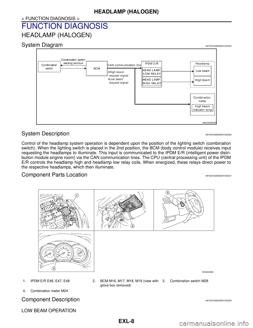
System DiagramINFOID:0000000001523225
System DescriptionINFOID:0000000001523226
Control of the headlamp system operation is dependent upon the position of the lighting switch (combination
switch). When the lighting switch is placed in the 2nd position, the BCM (body control module) receives input
requesting the headlamps to illuminate. This input is communicated to the IPDM E/R (intelligent power distri-
bution module engine room) via the CAN communication lines. The CPU (central processing unit) of the IPDM
E/R controls the headlamp high and headlamp low relay coils. When energized, these relays direct power to
the respective headlamps, which then illuminate.
Component Parts LocationINFOID:0000000001523227
Component DescriptionINFOID:0000000001523228
LOW BEAM OPERATION
AWLIA0002GB
1. IPDM E/R E46, E47, E48 2. BCM M16, M17, M18, M19 (view with
glove box removed)3. Combination switch M28
4. Combination meter M24
WKIA5469E
Page 3011 of 5883
EXL-10
< FUNCTION DIAGNOSIS >
HEADLAMP (XENON)
HEADLAMP (XENON)
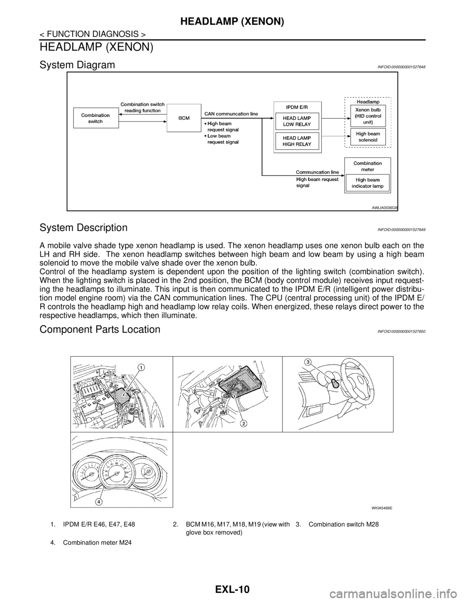
System DiagramINFOID:0000000001527648
System DescriptionINFOID:0000000001527649
A mobile valve shade type xenon headlamp is used. The xenon headlamp uses one xenon bulb each on the
LH and RH side. The xenon headlamp switches between high beam and low beam by using a high beam
solenoid to move the mobile valve shade over the xenon bulb.
Control of the headlamp system is dependent upon the position of the lighting switch (combination switch).
When the lighting switch is placed in the 2nd position, the BCM (body control module) receives input request-
ing the headlamps to illuminate. This input is then communicated to the IPDM E/R (intelligent power distribu-
tion model engine room) via the CAN communication lines. The CPU (central processing unit) of the IPDM E/
R controls the headlamp high and headlamp low relay coils. When energized, these relays direct power to the
respective headlamps, which then illuminate.
Component Parts LocationINFOID:0000000001527650
AWLIA0036GB
1. IPDM E/R E46, E47, E48 2. BCM M16, M17, M18, M19 (view with
glove box removed)3. Combination switch M28
4. Combination meter M24
WKIA5469E
Page 3013 of 5883
EXL-12
< FUNCTION DIAGNOSIS >
AUTO LIGHT SYSTEM
AUTO LIGHT SYSTEM
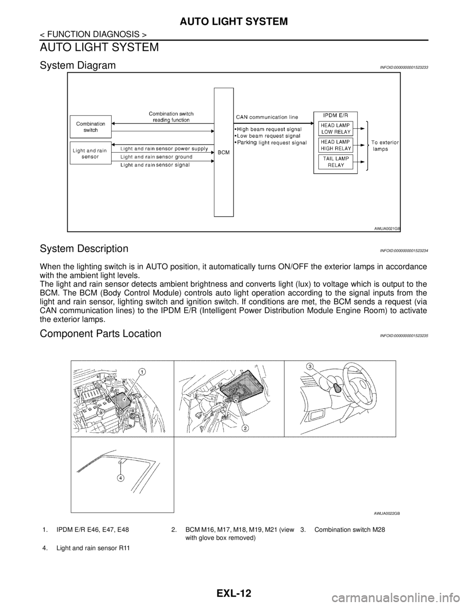
System DiagramINFOID:0000000001523233
System DescriptionINFOID:0000000001523234
When the lighting switch is in AUTO position, it automatically turns ON/OFF the exterior lamps in accordance
with the ambient light levels.
The light and rain sensor detects ambient brightness and converts light (lux) to voltage which is output to the
BCM. The BCM (Body Control Module) controls auto light operation according to the signal inputs from the
light and rain sensor, lighting switch and ignition switch. If conditions are met, the BCM sends a request (via
CAN communication lines) to the IPDM E/R (Intelligent Power Distribution Module Engine Room) to activate
the exterior lamps.
Component Parts LocationINFOID:0000000001523235
AWLIA0021GB
1. IPDM E/R E46, E47, E48 2. BCM M16, M17, M18, M19, M21 (view
with glove box removed)3. Combination switch M28
4. Light and rain sensor R11
AWLIA0022GB
Page 3019 of 5883

EXL-18
< FUNCTION DIAGNOSIS >
DAYTIME LIGHT SYSTEM
Component Description
INFOID:0000000001527657
Part Description
BCM Monitors lighting switch position, engine running status and parking brake status to
determine if conditions are set for daytime light system operation.
Requests the IPDM E/R via CAN communication lines to ground the daytime light
relay coil.
IPDM E/RControls ground to the daytime light relay coil based on requests from the BCM (via
CAN communication lines).
Combination switch
(Lighting & turn signal switch)Refer to XX-XX, "*****"
.
Combination meterMonitors engine running status and forwards that information to the BCM via CAN
communication lines.
Page 3020 of 5883

FRONT FOG LAMP
EXL-19
< FUNCTION DIAGNOSIS >
C
D
E
F
G
H
I
J
K
MA
B
EXL
N
O
P
FRONT FOG LAMP
System DiagramINFOID:0000000001523237
System DescriptionINFOID:0000000001523238
The BCM (Body Control Module) controls front fog lamp operation based on input from the lighting switch
(combination switch). The BCM requests (via CAN communication lines) the IPDM E/R (Intelligent Power Dis-
tribution Module Engine Room) to activate the integrated front fog lamp relay and requests the combination
meter to illuminate the front fog lamp light.
Component Parts LocationINFOID:0000000001523239
AWLIA0037GB
1. IPDM E/R E46, E47, E48 2. BCM M16, M17, M18, M19 (view with
glove box removed)3. Combination switch M28
4. Combination meter M24
WKIA5469E
Page 3025 of 5883
EXL-24
< FUNCTION DIAGNOSIS >
PARKING, LICENSE PLATE AND TAIL LAMPS
PARKING, LICENSE PLATE AND TAIL LAMPS
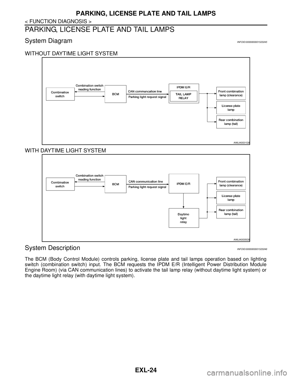
System DiagramINFOID:0000000001523245
WITHOUT DAYTIME LIGHT SYSTEM
WITH DAYTIME LIGHT SYSTEM
System DescriptionINFOID:0000000001523246
The BCM (Body Control Module) controls parking, license plate and tail lamps operation based on lighting
switch (combination switch) input. The BCM requests the IPDM E/R (Intelligent Power Distribution Module
Engine Room) (via CAN communication lines) to activate the tail lamp relay (without daytime light system) or
the daytime light relay (with daytime light system).
AWLIA0031GB
AWLIA0035GB
Page 3047 of 5883
EXL-46
< COMPONENT DIAGNOSIS >
PARKING LAMP CIRCUIT
PARKING LAMP CIRCUIT
WITH DAYTIME LIGHT SYSTEM
WITH DAYTIME LIGHT SYSTEM : DescriptionINFOID:0000000001523268
The IPDM E/R (Intelligent Power Distribution Module Engine Room) controls the daytime light relay based on
inputs from the BCM via the CAN communication lines. When the daytime light relay is energized power flows
to the front and rear combination lamps and the license plate lamps.
WITH DAYTIME LIGHT SYSTEM : Component Function CheckINFOID:0000000001523269
1.CHECK PARKING LAMP OPERATION
CONSULT-III
1. Select "TAIL LAMP" of IPDM E/R active test item.
2. With test items operating, check that the parking lamps are turned ON.
Is the parking lamp turned ON?
YES >> Parking lamp circuit is normal.
NO >> Refer to EXL-46, "
WITH DAYTIME LIGHT SYSTEM : Diagnosis Procedure".
WITH DAYTIME LIGHT SYSTEM : Diagnosis ProcedureINFOID:0000000001523270
1.CHECK PARKING LAMP FUSE
1. Turn the ignition switch OFF.
2. Check that the following fuse is not open.
Is the fuse open?
YES >> Repair the harness and replace the fuse.
NO >> GO TO 2
2.CHECK DAYTIME LIGHT RELAY OUTPUT (VOLTAGE)
CONSULT-III
1. Turn the ignition switch OFF.
2. Disconnect the front or rear combination lamp connectors.
3. Turn the ignition switch ON.
4. Select "TAIL LAMP" of IPDM E/R active test item.
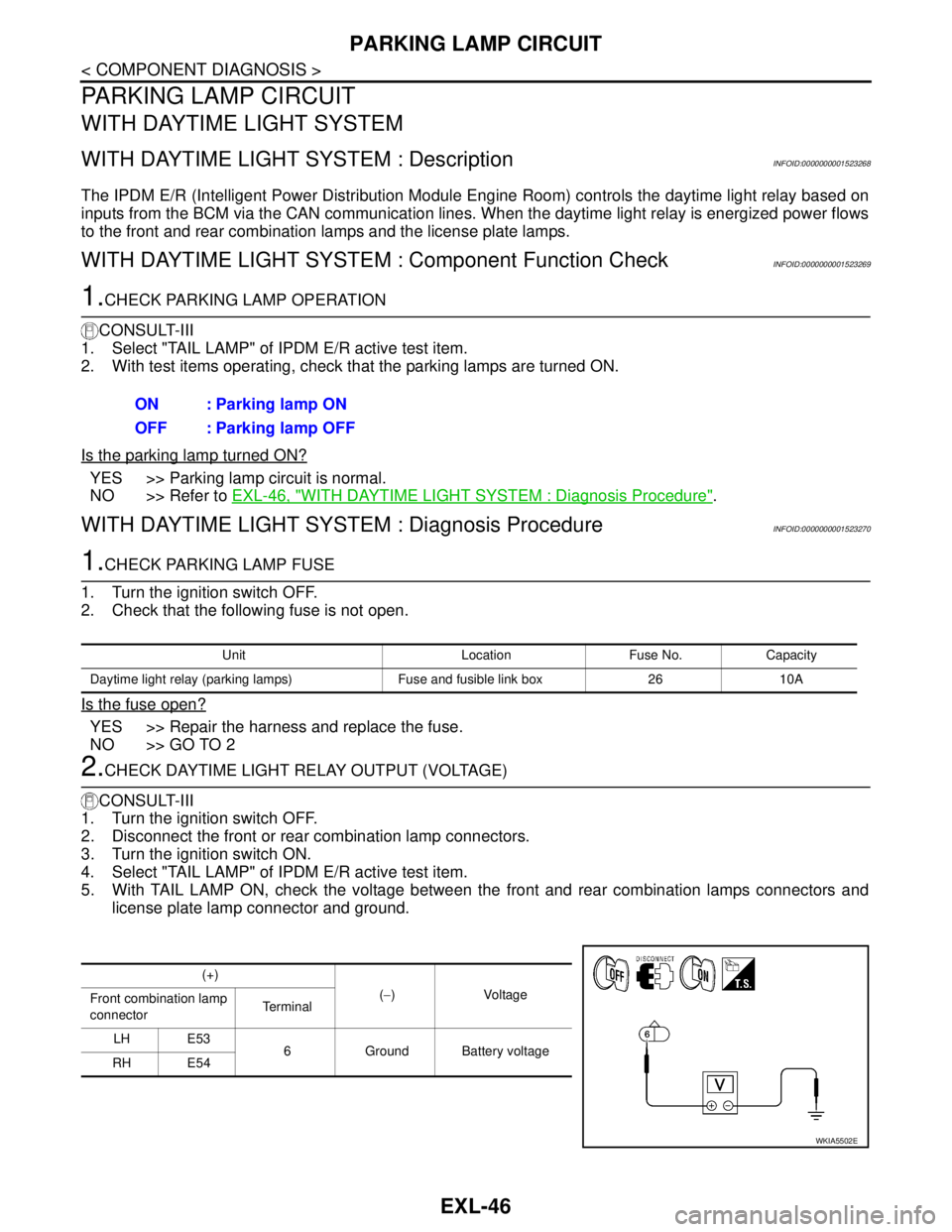
5. With TAIL LAMP ON, check the voltage between the front and rear combination lamps connectors and
license plate lamp connector and ground.ON : Parking lamp ON
OFF : Parking lamp OFF
Unit Location Fuse No. Capacity
Daytime light relay (parking lamps) Fuse and fusible link box 26 10A
(+)
(−)Voltage
Front combination lamp
connectorTe r m i n a l
LH E53
6 Ground Battery voltage
RH E54
WKIA5502E