2007 NISSAN TIIDA EC Engine Control System
[x] Cancel search: EC Engine Control SystemPage 3049 of 5883
EXL-48
< COMPONENT DIAGNOSIS >
PARKING LAMP CIRCUIT
2. Disconnect the front combination lamp connectors, rear combination lamp connectors or license plate
lamp connectors.
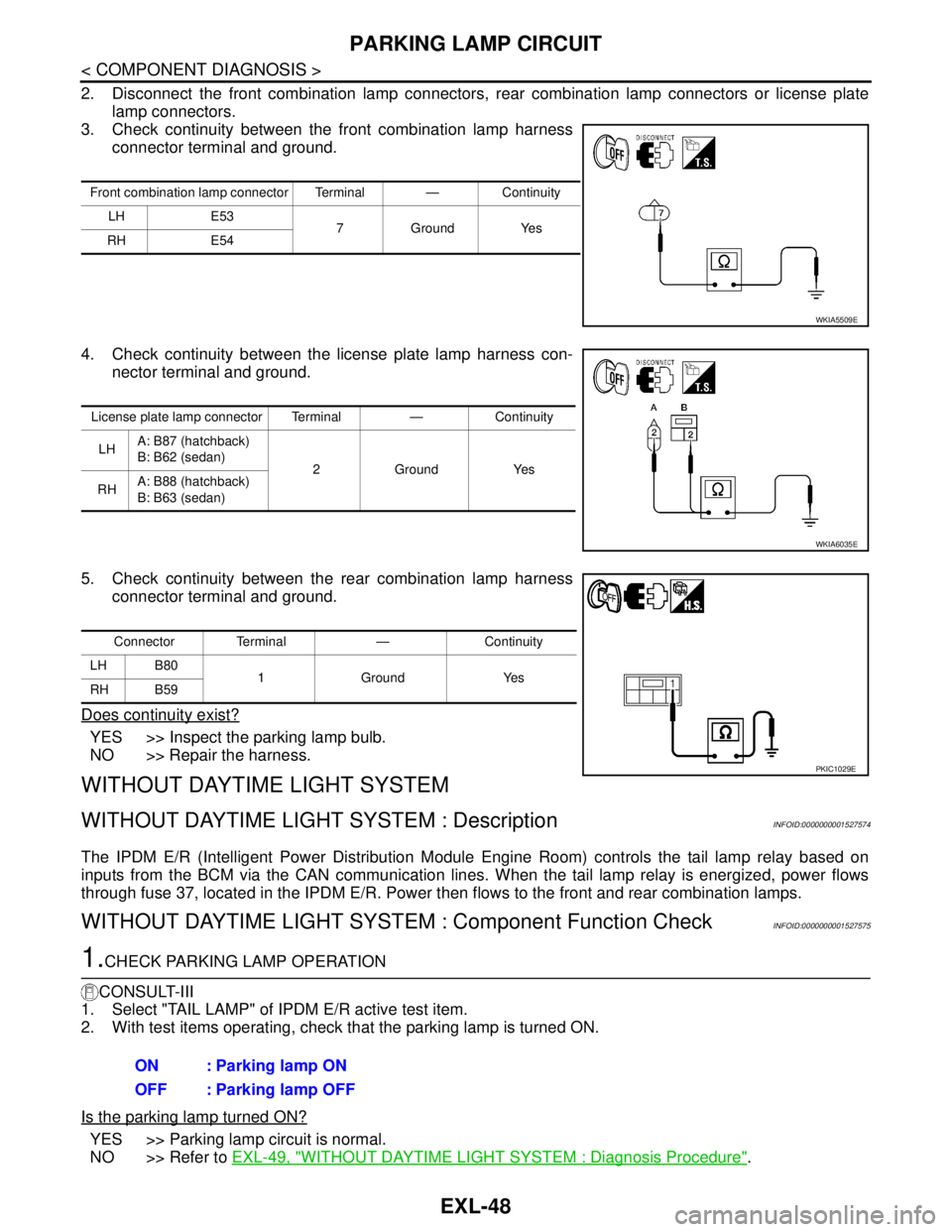
3. Check continuity between the front combination lamp harness
connector terminal and ground.
4. Check continuity between the license plate lamp harness con-
nector terminal and ground.
5. Check continuity between the rear combination lamp harness
connector terminal and ground.
Does continuity exist?
YES >> Inspect the parking lamp bulb.
NO >> Repair the harness.
WITHOUT DAYTIME LIGHT SYSTEM
WITHOUT DAYTIME LIGHT SYSTEM : DescriptionINFOID:0000000001527574
The IPDM E/R (Intelligent Power Distribution Module Engine Room) controls the tail lamp relay based on
inputs from the BCM via the CAN communication lines. When the tail lamp relay is energized, power flows
through fuse 37, located in the IPDM E/R. Power then flows to the front and rear combination lamps.
WITHOUT DAYTIME LIGHT SYSTEM : Component Function CheckINFOID:0000000001527575
1.CHECK PARKING LAMP OPERATION
CONSULT-III
1. Select "TAIL LAMP" of IPDM E/R active test item.
2. With test items operating, check that the parking lamp is turned ON.
Is the parking lamp turned ON?
YES >> Parking lamp circuit is normal.
NO >> Refer to EXL-49, "
WITHOUT DAYTIME LIGHT SYSTEM : Diagnosis Procedure".
Front combination lamp connector Terminal — Continuity
LH E53
7GroundYes
RH E54
WKIA5509E
License plate lamp connector Terminal — Continuity
LHA: B87 (hatchback)
B: B62 (sedan)
2GroundYes
RHA: B88 (hatchback)
B: B63 (sedan)
WKIA6035E
Connector Terminal — Continuity
LH B80
1Ground Yes
RH B59
PKIC1029E
ON : Parking lamp ON
OFF : Parking lamp OFF
Page 3195 of 5883

GI-1
GENERAL INFORMATION
C
D
E
F
G
H
I
J
K
L
MB
GI
SECTION GI
N
O
P
CONTENTS
GENERAL INFORMATION
HOW TO USE THIS MANUAL ......................3
HOW TO USE THIS MANUAL ............................3
Description ................................................................3
Terms ........................................................................3
Units ..........................................................................3
Contents ....................................................................3
Relation between Illustrations and Descriptions .......4
Component ................................................................4
How to Follow Trouble Diagnosis ..............................5
How to Read Wiring Diagram ....................................9
Abbreviations ..........................................................16
HOW TO FOLLOW TROUBLE DIAGNOSES ....18
Description ..............................................................18
How to Follow Test Groups in Trouble Diagnosis ....18
Key to Symbols Signifying Measurements or Pro-
cedures ...................................................................
19
HOW TO READ WIRING DIAGRAMS ...............21
Connector symbols .................................................21
Sample/wiring diagram -example- ...........................22
Description ..............................................................23
ABBREVIATIONS ..............................................25
Abbreviation List ......................................................25
TIGHTENING TORQUE OF STANDARD
BOLTS ................................................................
26
Tightening Torque Table .........................................26
RECOMMENDED CHEMICAL PRODUCTS
AND SEALANTS ................................................
27
Recommended Chemical Products and Sealants ....27
TERMINOLOGY .................................................28
SAE J1930 Terminology List ...................................28
FEATURES OF NEW MODEL .....................32
IDENTIFICATION INFORMATION .....................32
Model Variation .......................................................32
Dimensions ..............................................................41
Wheels & Tires ........................................................42
PRECAUTION ..............................................43
PRECAUTIONS .................................................43
Description ...............................................................43
Precaution for Supplemental Restraint System
(SRS) "AIR BAG" and "SEAT BELT PRE-TEN-
SIONER" .................................................................
43
Precaution Necessary for Steering Wheel Rota-
tion After Battery Disconnect ...................................
43
General Precaution ..................................................44
Precaution for Three Way Catalyst ..........................45
Precaution for Fuel (Unleaded Regular Gasoline
Recommended) .......................................................
45
Precaution for Multiport Fuel Injection System or
Engine Control System ............................................
46
Precaution for Hoses ...............................................46
Precaution for Engine Oils .......................................47
Precaution for Air Conditioning ................................47
LIFTING POINT .................................................48
Special Service Tool ................................................48
Garage Jack and Safety Stand and 2-Pole Lift .......48
Board-On Lift ...........................................................49
TOW TRUCK TOWING .....................................50
Tow Truck Towing ...................................................50
Vehicle Recovery (Freeing a Stuck Vehicle) ...........50
BASIC INSPECTION ...................................51
SERVICE INFORMATION FOR ELECTRICAL
INCIDENT ..........................................................
51
Work Flow ................................................................51
Control Units and Electrical Parts ............................51
How to Check Terminal ...........................................52
Intermittent Incident .................................................55
Circuit Inspection .....................................................58
CONSULT-III CHECKING SYSTEM .................63
Page 3222 of 5883

GI-28
< HOW TO USE THIS MANUAL >
TERMINOLOGY
TERMINOLOGY
SAE J1930 Terminology ListINFOID:0000000001691466
All emission related terms used in this publication in accordance with SAE J1930 are listed. Accordingly, new
terms, new acronyms/abbreviations and old terms are listed in the following chart.
NEW TERMNEW ACRONYM /
ABBREVIATIONOLD TERM
Air cleaner ACL Air cleaner
Barometric pressure BARO ***
Barometric pressure sensor-BCDD BAROS-BCDD BCDD
Camshaft position CMP ***
Camshaft position sensor CMPS Crank angle sensor
Canister *** Canister
Carburetor CARB Carburetor
Charge air cooler CAC Intercooler
Closed loop CL Closed loop
Closed throttle position switch CTP switch Idle switch
Clutch pedal position switch CPP switch Clutch switch
Continuous fuel injection system CFI system ***
Continuous trap oxidizer system CTOX system ***
Crankshaft position CKP ***
Crankshaft position sensor CKPS ***
Data link connector DLC ***
Data link connector for CONSULT-III DLC for CONSULT-III Diagnostic connector for CONSULT-III
Diagnostic test mode DTM Diagnostic mode
Diagnostic test mode selector DTM selector Diagnostic mode selector
Diagnostic test mode I DTM I Mode I
Diagnostic test mode II DTM II Mode II
Diagnostic trouble code DTC Malfunction code
Direct fuel injection system DFI system ***
Distributor ignition system DI system Ignition timing control
Early fuel evaporation-mixture heater EFE-mixture heater Mixture heater
Early fuel evaporation system EFE system Mixture heater control
Electrically erasable programmable read
only memoryEEPROM ***
Electronic ignition system EI system Ignition timing control
Engine control EC ***
Engine control module ECM ECCS control unit
Engine coolant temperature ECT Engine temperature
Engine coolant temperature sensor ECTS Engine temperature sensor
Engine modification EM ***
Engine speed RPM Engine speed
Erasable programmable read only memory EPROM ***
Evaporative emission canister EVAP canister Canister
Evaporative emission system EVAP system Canister control solenoid valve
Exhaust gas recirculation valve EGR valve EGR valve
Page 3223 of 5883

TERMINOLOGY
GI-29
< HOW TO USE THIS MANUAL >
C
D
E
F
G
H
I
J
K
L
MB
GI
N
O
P
Exhaust gas recirculation control-BPT
valveEGRC-BPT valve BPT valve
Exhaust gas recirculation control-solenoid
valveEGRC-solenoid valve EGR control solenoid valve
Exhaust gas recirculation temperature sen-
sor
EGRT sensor Exhaust gas temperature sensor
EGR temperature sensor
Flash electrically erasable programmable
read only memoryFEEPROM ***
Flash erasable programmable read only
memoryFEPROM ***
Flexible fuel sensor FFS ***
Flexible fuel system FF system ***
Fuel pressure regulator *** Pressure regulator
Fuel pressure regulator control solenoid
valve*** PRVR control solenoid valve
Fuel trim FT ***
Heated Oxygen sensor HO2S Exhaust gas sensor
Idle air control system IAC system Idle speed control
Idle air control valve-air regulator IACV-air regulator Air regulator
Idle air control valve-auxiliary air control
valveIACV-AAC valve Auxiliary air control (AAC) valve
Idle air control valve-FICD solenoid valve IACV-FICD solenoid valve FICD solenoid valve
Idle air control valve-idle up control sole-
noid valveIACV-idle up control solenoid valve Idle up control solenoid valve
Idle speed control-FI pot ISC-FI pot FI pot
Idle speed control system ISC system ***
Ignition control IC ***
Ignition control module ICM ***
Indirect fuel injection system IFI system ***
Intake air IA Air
Intake air temperature sensor IAT sensor Air temperature sensor
Knock *** Detonation
Knock sensor KS Detonation sensor
Malfunction indicator lamp MIL Check engine light
Manifold absolute pressure MAP ***
Manifold absolute pressure sensor MAPS ***
Manifold differential pressure MDP ***
Manifold differential pressure sensor MDPS ***
Manifold surface temperature MST ***
Manifold surface temperature sensor MSTS ***
Manifold vacuum zone MVZ ***
Manifold vacuum zone sensor MVZS ***
Mass air flow sensor MAFS Air flow meter
Mixture control solenoid valve MC solenoid valve Air-fuel ratio control solenoid valve
Multiport fuel injection System MFI system Fuel injection controlNEW TERMNEW ACRONYM /
ABBREVIATIONOLD TERM
Page 3239 of 5883
PRECAUTIONS
GI-45
< PRECAUTION >
C
D
E
F
G
H
I
J
K
L
MB
GI
N
O
P
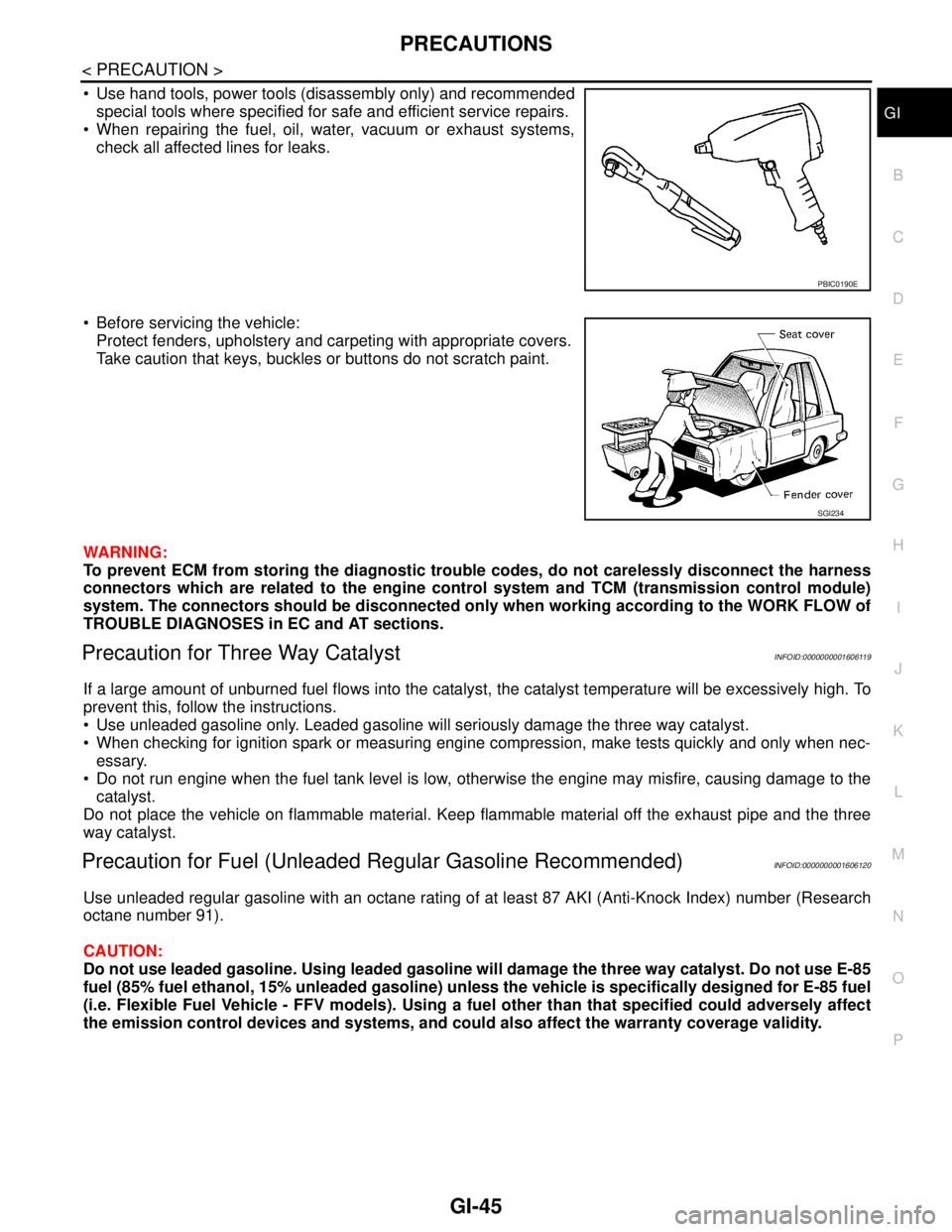
Use hand tools, power tools (disassembly only) and recommended
special tools where specified for safe and efficient service repairs.
When repairing the fuel, oil, water, vacuum or exhaust systems,
check all affected lines for leaks.
Before servicing the vehicle:
Protect fenders, upholstery and carpeting with appropriate covers.
Take caution that keys, buckles or buttons do not scratch paint.
WARNING:
To prevent ECM from storing the diagnostic trouble codes, do not carelessly disconnect the harness
connectors which are related to the engine control system and TCM (transmission control module)
system. The connectors should be disconnected only when working according to the WORK FLOW of
TROUBLE DIAGNOSES in EC and AT sections.
Precaution for Three Way CatalystINFOID:0000000001606119
If a large amount of unburned fuel flows into the catalyst, the catalyst temperature will be excessively high. To
prevent this, follow the instructions.
Use unleaded gasoline only. Leaded gasoline will seriously damage the three way catalyst.
When checking for ignition spark or measuring engine compression, make tests quickly and only when nec-
essary.
Do not run engine when the fuel tank level is low, otherwise the engine may misfire, causing damage to the
catalyst.
Do not place the vehicle on flammable material. Keep flammable material off the exhaust pipe and the three
way catalyst.
Precaution for Fuel (Unleaded Regular Gasoline Recommended)INFOID:0000000001606120
Use unleaded regular gasoline with an octane rating of at least 87 AKI (Anti-Knock Index) number (Research
octane number 91).
CAUTION:
Do not use leaded gasoline. Using leaded gasoline will damage the three way catalyst. Do not use E-85
fuel (85% fuel ethanol, 15% unleaded gasoline) unless the vehicle is specifically designed for E-85 fuel
(i.e. Flexible Fuel Vehicle - FFV models). Using a fuel other than that specified could adversely affect
the emission control devices and systems, and could also affect the warranty coverage validity.
PBIC0190E
SGI234
Page 3240 of 5883
GI-46
< PRECAUTION >
PRECAUTIONS
Precaution for Multiport Fuel Injection System or Engine Control System
INFOID:0000000001606121
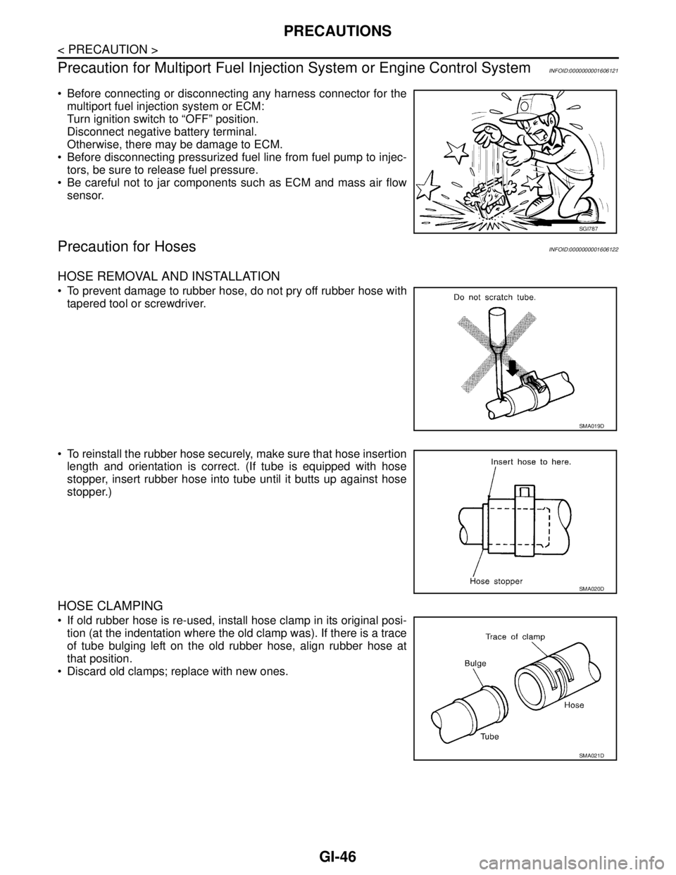
Before connecting or disconnecting any harness connector for the
multiport fuel injection system or ECM:
Turn ignition switch to “OFF” position.
Disconnect negative battery terminal.
Otherwise, there may be damage to ECM.
Before disconnecting pressurized fuel line from fuel pump to injec-
tors, be sure to release fuel pressure.
Be careful not to jar components such as ECM and mass air flow
sensor.
Precaution for HosesINFOID:0000000001606122
HOSE REMOVAL AND INSTALLATION
To prevent damage to rubber hose, do not pry off rubber hose with
tapered tool or screwdriver.
To reinstall the rubber hose securely, make sure that hose insertion
length and orientation is correct. (If tube is equipped with hose
stopper, insert rubber hose into tube until it butts up against hose
stopper.)
HOSE CLAMPING
If old rubber hose is re-used, install hose clamp in its original posi-
tion (at the indentation where the old clamp was). If there is a trace
of tube bulging left on the old rubber hose, align rubber hose at
that position.
Discard old clamps; replace with new ones.
SGI787
SMA019D
SMA020D
SMA021D
Page 3245 of 5883
SERVICE INFORMATION FOR ELECTRICAL INCIDENT
GI-51
< BASIC INSPECTION >
C
D
E
F
G
H
I
J
K
L
MB
GI
N
O
PBASIC INSPECTION
SERVICE INFORMATION FOR ELECTRICAL INCIDENT
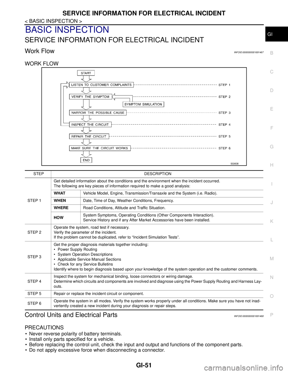
Work FlowINFOID:0000000001691467
WORK FLOW
Control Units and Electrical PartsINFOID:0000000001691468
PRECAUTIONS
Never reverse polarity of battery terminals.
Install only parts specified for a vehicle.
Before replacing the control unit, check the input and output and functions of the component parts.
Do not apply excessive force when disconnecting a connector.
SGI838
STEP DESCRIPTION
STEP 1Get detailed information about the conditions and the environment when the incident occurred.
The following are key pieces of information required to make a good analysis:
WHATVehicle Model, Engine, Transmission/Transaxle and the System (i.e. Radio).
WHENDate, Time of Day, Weather Conditions, Frequency.
WHERERoad Conditions, Altitude and Traffic Situation.
HOWSystem Symptoms, Operating Conditions (Other Components Interaction).
Service History and if any After Market Accessories have been installed.
STEP 2Operate the system, road test if necessary.
Verify the parameter of the incident.
If the problem cannot be duplicated, refer to “Incident Simulation Tests”.
STEP 3Get the proper diagnosis materials together including:
Power Supply Routing
System Operation Descriptions
Applicable Service Manual Sections
Check for any Service Bulletins
Identify where to begin diagnosis based upon your knowledge of the system operation and the customer comments.
STEP 4Inspect the system for mechanical binding, loose connectors or wiring damage.
Determine which circuits and components are involved and diagnose using the Power Supply Routing and Harness Lay-
outs.
STEP 5 Repair or replace the incident circuit or component.
STEP 6Operate the system in all modes. Verify the system works properly under all conditions. Make sure you have not inad-
vertently created a new incident during your diagnosis or repair steps.
Page 3257 of 5883
CONSULT-III CHECKING SYSTEM
GI-63
< BASIC INSPECTION >
C
D
E
F
G
H
I
J
K
L
MB
GI
N
O
PCONSULT-III CHECKING SYSTEM
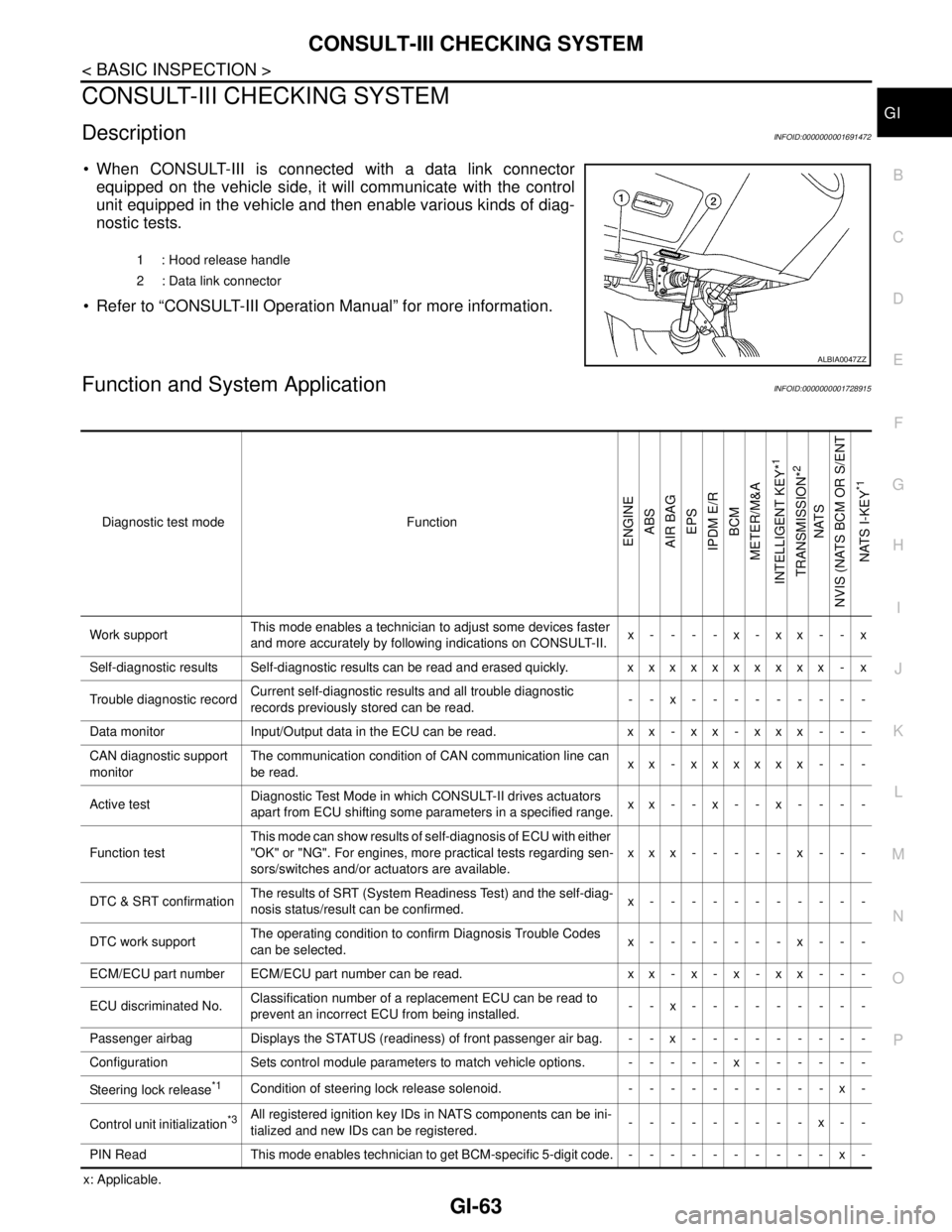
DescriptionINFOID:0000000001691472
When CONSULT-III is connected with a data link connector
equipped on the vehicle side, it will communicate with the control
unit equipped in the vehicle and then enable various kinds of diag-
nostic tests.
Refer to “CONSULT-III Operation Manual” for more information.
Function and System ApplicationINFOID:0000000001728915
x: Applicable.1 : Hood release handle
2 : Data link connector
ALBIA0047ZZ
Diagnostic test mode Function
ENGINE
ABS
AIR BAG
EPS
IPDM E/R
BCM
METER/M&A
INTELLIGENT KEY*
1
TRANSMISSION*
2
NATS
NVIS (NATS BCM OR S/ENT
NATS I-KEY
*1
Work supportThis mode enables a technician to adjust some devices faster
and more accurately by following indications on CONSULT-II.x----x-xx--x
Self-diagnostic results Self-diagnostic results can be read and erased quickly. xxxxxxxxxx - x
Trouble diagnostic recordCurrent self-diagnostic results and all trouble diagnostic
records previously stored can be read.--x---------
Data monitor Input/Output data in the ECU can be read. x x - x x - x x x - - -
CAN diagnostic support
monitorThe communication condition of CAN communication line can
be read.xx - xxxxxx - - -
Active testDiagnostic Test Mode in which CONSULT-II drives actuators
apart from ECU shifting some parameters in a specified range.xx--x--x----
Function testThis mode can show results of self-diagnosis of ECU with either
"OK" or "NG". For engines, more practical tests regarding sen-
sors/switches and/or actuators are available.xxx-----x---
DTC & SRT confirmationThe results of SRT (System Readiness Test) and the self-diag-
nosis status/result can be confirmed.x-----------
DTC work supportThe operating condition to confirm Diagnosis Trouble Codes
can be selected.x-------x---
ECM/ECU part number ECM/ECU part number can be read. x x - x - x - x x - - -
ECU discriminated No.Classification number of a replacement ECU can be read to
prevent an incorrect ECU from being installed.--x---------
Passenger airbag Displays the STATUS (readiness) of front passenger air bag. --x---------
Configuration Sets control module parameters to match vehicle options. -----x------
Steering lock release
*1Condition of steering lock release solenoid. ----------x-
Control unit initialization
*3All registered ignition key IDs in NATS components can be ini-
tialized and new IDs can be registered.---------x--
PIN Read This mode enables technician to get BCM-specific 5-digit code.----------x-