2007 NISSAN TIIDA starter
[x] Cancel search: starterPage 2413 of 5883
EC-1064
< FUNCTION DIAGNOSIS >[K9K]
FUEL INJECTION CONTROL
energy returned by the piezo actuator is reused, which keeps down the amount of energy that has to be sup-
plied for the next injection process.
Engine Synchronisation
One of the determining factors for fuel injection control is knowing the position of each of the pistons in their
respective cylinders at all times.
The angular position is measured by means of a magneto-inductive sensor which is excited by the teeth
machined onto the flywheel; this is known as the crankshaft position sensor. The flywheel has 60 teeth, each 6
degrees apart; 2 of these teeth are missing to form a notch.
A second sensor (Hall-effect sensor), stimulated by a tooth machined onto the camshaft, which turns at half
the engine speed, provides a signal relating to the progress of the injection cycle. Indeed, when the piston of
cylinder 1 is at top dead centre (TDC), either at the end of the compression stroke or at the end of the exhaust
stroke, the camshaft position sensor enables a distinction to be made between these two states.
By comparing the signals from these two sensors, the computer is able to provide all its systems with synchro-
nisation parameters, namely: the angular position of the flywheel, engine speed, the number of the active fuel
injector and the progress of the injection cycle.
This module also supplies the system with the rotation speed signal.
The camshaft position sensor is only used when starting the engine. As soon as the engine is running by itself
(not being cranked by the starter), the signal provided by the crankshaft position sensor is sufficient. If the
camshaft position sensor should fail while the engine is running, this will not affect the operation of the engine.
Quantity of Fuel Injected and Control of Start of Injection
The parameters for controlling injection are, for each cylinder, the quantity to be injected and the start of
injection. These are calculated by the ECM from the following information:
- Engine speed.
- Accelerator pedal position.
- Turbocharge air pressure.
- Engine coolant temperature.
- Intake air temperature.
- Fuel pump temperature.
- Mass air flow.
- Pressure of fuel in the rail.
Station to Station Flow Regulation
The aim of this regulation process is to facilitate smooth engine operation by compensating for the system
variations (fuel injectors, compression rate, etc.) which affect the torque generated by each cylinder during
combustion.
The regulation process is only active at idle speed, with a warm engine and on condition that the engine speed
is sufficiently stable. An injection timing correction coefficient is assigned to each cylinder; this is "learning" all
the time the regulation process is active and remains fixed at the last value that was learned when the regula-
tion is inactive.
At each new cycle, the coefficients are initialised to 1.
Cylinder Balancing Control
This controller allows smooth behavior of running engine, reduction of noise and oscillations in the drivetrain
by compensating for system dispersions (fuel injectors, compression ratio, manufacturing tolerances of cylin-
ders or valves...) having an influence on the torque generated by each cylinder during combustion.
The controller is only activated if engine is in idle, warm and not too rough. Corrective coefficient on the injec-
tion time is associated with each cylinder that is learnt as soon as the regulation is active. Otherwise it remains
with its last memorized value.
At each new driving cycle, coefficients are initialized to 1.
Page 2573 of 5883
EC-1224
< ECU DIAGNOSIS >[K9K]
ECM
Test Condition: Engine Stopped and Ignition Switch ON
Order Function Parameter Display and notes Trouble diagnosis
1 Battery voltage BATTERY VOLTAGE12 V < BATTERY VOLTAGE <
14.4 VIn the event of a malfunction, per-
form the trouble diagnosis for
CHARGING SYSTEM.
2 Engine speed ENGINE SPEEDIndicates the engine's rotational
speed in rpm.In the event of a malfunction, per-
form the trouble diagnosis for DTC
P0335 CKP SENSOR.
3Engine coolant tem-
peratureWATER TEMPClose to ambient temperature
(cold engine).
Indicates the engine coolant tem-
perature in ° C.In the event of a malfunction, per-
form the trouble diagnosis for DTC
P0115 ETC SENSOR.
4Accelerator pedal po-
sitionACCEL/PDL POS0%= ACCEL/PDL POS < 100%
Indicates the percentage of the
pedal position between no load
and full load positionIn the event of a malfunction, per-
form the trouble diagnosis for APP
SENSOR (DTC P0225, and P2120)
and SENSOR POWER SUPPLY
(DTC P0641 and P0651).
5 Inlet air temperature INLET AIR TEMIndicates the intake air tempera-
ture in °C. This information is pro-
vided by the IAT sensor.In the event of a malfunction, per-
form the trouble diagnosis for DTC
P0110 IAT SENSOR.
6Fuel pump tempera-
tureFUEL TEMPClose to ambient temperature
(cold engine).
Indicates the fuel pump tempera-
ture in ° C.In the event of a malfunction, per-
form the trouble diagnosis for DTC
P0180 FTT SENSOR.
7 Intake air pressureATOMOS PRESS700 mbar < ATOMOS PRESS <
11 0 0 m b a r
Indicates the ambient barometric
pressure in mbar. The sensor is
incorporated in the ECM.If not consistent, check ATOMOS
PRESS = INLET PRESS = local
ambient barometric pressure, with
the engine stopped and ignition
switch ON.
INLET PRESSIndicates the pressure in the tur-
bocharger in mbar.
8 Fuel rail pressure RAIL PRESSUREApproximately 0 bar
Indicates the fuel rail pressure in
bar of the diesel fuel in the fuel
rail.
This pressure is supplied by the
fuel rail pressure sensor.In the event of a malfunction, per-
form the trouble diagnosis for DTC
P0190 and P1089 FRP SENSOR.
9Engine MOTORSTOPPED
Indicates the current status of the
engine.
STOPPED
STARTER
ACTIVATED
RUNNINGNONE.
Page 2575 of 5883
EC-1226
< ECU DIAGNOSIS >[K9K]
ECM
AIR CIRC SUBFUNCTION (TURBOCHARGER/INTAKE AIR)
Test Condition: Engine Stopped and Ignition Switch ON
9 Engine MOTORRUNNING
Indicates the current status of
the engine.
STOPPED
STARTER
A C T I VAT E D
RUNNINGNONE.
10 Engine immobilizer ENGINE IMMOBIINACTIVE
Indicates the status of the immo-
bilizer system.
INACTIVE: The ECM has rec-
ognized the immobilizer code
transmitted by the Intelligent
Key unit or BCM.
ACTIVE: The ECM does not
recognize the immobilizer
code transmitted by the Intelli-
gent Key unit or BCM.If ACTIVE, perform the trouble diag-
nosis for NATS.
11 Vehicle speed VEHICLE SPEED0 km/h (mph)
Indicates the vehicle speed in
km/h (mph). This parameter is
transmitted by the “ABS actuator
and electric unit (control unit)” or
combination meter via CAN
communication line.Perform the trouble diagnosis for
CAN communication line. Perform
the trouble diagnosis for “ABS actu-
ator and electric unit (control unit)” or
combination meter. Order Function Parameter Display and notes Trouble diagnosis
Order Function Parameter Display and notes Trouble diagnosis
1 Intake air pressureATOMOS PRESS700 mbar < ATOMOS PRESS
< 1100 mbar
Indicates the ambient baromet-
ric pressure in mbar. The sen-
sor is incorporated in the ECM.If not consistent, check ATOMOS
PRESS = INLET PRESS = local
ambient barometric pressure, with
the engine stopped and ignition
switch ON.
INLET PRESSIndicates the pressure in the
turbocharger in mbar.
2 Intake airATMOS PRES SEN V1.6V < ATMOS PRES SEN V <
4.9VIn the event of a malfunction, per-
form the trouble diagnosis for DTC
P2226 BARO SENSOR.
AIR TEMP SEN V0.1V < AIR TEMP SEN V <
4.8VIn the event of a malfunction, per-
form the trouble diagnosis for DTC
P0110 IAT SENSOR.
3air flowAIR FLOW0 mg/st
Mass air flow estimated by the
ECM.
In the event of a malfunction, per-
form the trouble diagnosis for DTC
P0100 MAF SENSOR. AIR FLOW DEMANDMass air flow request set point
the ECM.
AIR FLOW SUPLY V0.27V < AIR FLOW SUPLY V <
4.56V
Indicates voltage of the mass
air flow sensor.
4 Inlet air temperature INLET AIR TEMIndicates the intake air temper-
ature in °C. This information is
provided by the IAT sensor.In the event of a malfunction, per-
form the trouble diagnosis for DTC
P0110 IAT SENSOR.
5 Engine speed ENGINE SPEED0 rpm
Indicates the engine's rotation-
al speed in rpm.In the event of a malfunction, per-
form the trouble diagnosis for DTC
P0335 CKP SENSOR.
Page 2606 of 5883
ENGINE DOES NOT START OR STARTS WITH DIFFICULTY
EC-1257
< SYMPTOM DIAGNOSIS >[K9K]
C
D
E
F
G
H
I
J
K
L
MA
EC
N
P O
ENGINE DOES NOT START OR STARTS WITH DIFFICULTY
DescriptionINFOID:0000000001162701
CHART 2: ENGINE DOES NOT START OR STARTS WITH DIFFICULTY
Diagnosis ProcedureINFOID:0000000001162702
1.CHECK FUEL
Check that the fuel reservoir is correctly filled and with the right fuel.
>> GO TO 2.
2.CHECK BATTERY
Check the battery. Refer to PG-6, "
Removal and Installation".
Is the inspection result normal?
YES >> GO TO 3.
NO >> Repair or replace battery. Refer to PG-6, "
Removal and Installation"
3.CHECK STARTER MOTOR
Check the starter and starter motor relay. Refer to STR-35, "
Removal and Installation".
Is the inspection result normal?
YES >> GO TO 4.
NO >> Repair or replace starter motor or starter relay. Refer to STR-35, "
Removal and Installation"
4.CHECK ECM RELAY
Check the ECM relay. Refer to EC-1184, "
Diagnosis Procedure".
Is the inspection result normal?
YES >> GO TO 5.
NO >> Replace IPDM E/R. Refer to PCS-30, "
Removal and Installation of IPDM E/R".
5.CHECK ECM POWER SUPPLY AND GROUND CIRCUIT
Check ECM power supply and ground circuit. Refer to EC-1106, "
Diagnosis Procedure".
Is the inspection result normal?
YES >> GO TO 6.
NO >> Repair or replace harness or connector.
6.CHECK WIRING HARNESS
Visually check the condition of the engine wiring harness.
Is the inspection result normal?
YES >> GO TO 7.
NO >> Repair or replace harness or connector.
7.CHECK CAMSHAFT POSITION SENSOR
Check the camshaft position sensor. Refer to EC-1152, "
Component Inspection".
Is the inspection result normal?
YES >> GO TO 8.
NO >> Repair or replace.
8.CHECK CAMSHAFT
Check the camshaft. Refer to EM-300, "
Inspection".
Is the inspection result normal?
YES >> GO TO 9.
NO >> Replace camshaft. Refer to EM-298, "
Removal and Installation".
9.CHECK AIR INTAKE SYSTEM
Check air intake system. Refer to EM-269, "
Removal and Installation".
Page 2608 of 5883
STARTING DIFFICULT WITH COLD ENGINE
EC-1259
< SYMPTOM DIAGNOSIS >[K9K]
C
D
E
F
G
H
I
J
K
L
MA
EC
N
P O
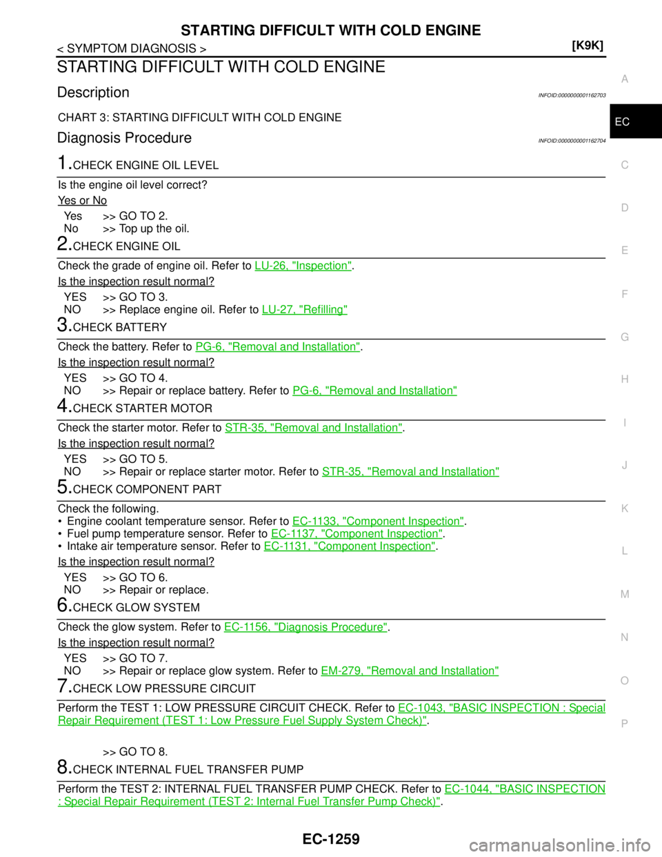
STARTING DIFFICULT WITH COLD ENGINE
DescriptionINFOID:0000000001162703
CHART 3: STARTING DIFFICULT WITH COLD ENGINE
Diagnosis ProcedureINFOID:0000000001162704
1.CHECK ENGINE OIL LEVEL
Is the engine oil level correct?
Ye s o r N o
Yes >> GO TO 2.
No >> Top up the oil.
2.CHECK ENGINE OIL
Check the grade of engine oil. Refer to LU-26, "
Inspection".
Is the inspection result normal?
YES >> GO TO 3.
NO >> Replace engine oil. Refer to LU-27, "
Refilling"
3.CHECK BATTERY
Check the battery. Refer to PG-6, "
Removal and Installation".
Is the inspection result normal?
YES >> GO TO 4.
NO >> Repair or replace battery. Refer to PG-6, "
Removal and Installation"
4.CHECK STARTER MOTOR
Check the starter motor. Refer to STR-35, "
Removal and Installation".
Is the inspection result normal?
YES >> GO TO 5.
NO >> Repair or replace starter motor. Refer to STR-35, "
Removal and Installation"
5.CHECK COMPONENT PART
Check the following.
Engine coolant temperature sensor. Refer to EC-1133, "
Component Inspection".
Fuel pump temperature sensor. Refer to EC-1137, "
Component Inspection".
Intake air temperature sensor. Refer to EC-1131, "
Component Inspection".
Is the inspection result normal?
YES >> GO TO 6.
NO >> Repair or replace.
6.CHECK GLOW SYSTEM
Check the glow system. Refer to EC-1156, "
Diagnosis Procedure".
Is the inspection result normal?
YES >> GO TO 7.
NO >> Repair or replace glow system. Refer to EM-279, "
Removal and Installation"
7.CHECK LOW PRESSURE CIRCUIT
Perform the TEST 1: LOW PRESSURE CIRCUIT CHECK. Refer to EC-1043, "
BASIC INSPECTION : Special
Repair Requirement (TEST 1: Low Pressure Fuel Supply System Check)".
>> GO TO 8.
8.CHECK INTERNAL FUEL TRANSFER PUMP
Perform the TEST 2: INTERNAL FUEL TRANSFER PUMP CHECK. Refer to EC-1044, "
BASIC INSPECTION
: Special Repair Requirement (TEST 2: Internal Fuel Transfer Pump Check)".
Page 2646 of 5883
PRECAUTIONS
EC-1297
< PRECAUTION >[K9K]
C
D
E
F
G
H
I
J
K
L
MA
EC
N
P O
NOTE:
Before any work is carried out on the high pressure injection system, protect:
the accessories and timing belts,
the electrical accessories, (starter, alternator, electric power assisted steering pump),
the flywheel surface, to prevent any diesel from running onto the clutch friction plate.
Check that you have plugs for the unions to be opened (set of plugs available from the Parts Department).
The plugs are single-use only. After use, they must be discarded (once used they are soiled and cleaning is
not sufficient to make them reusable). Unused plugs must be discarded.
Check that you have hermetically resealable plastic bags for storing removed parts. Stored parts will there-
fore be less subject to the risk of impurities. The bags are to be used once only, and discarded after use.
Use lint-free cleaning cloths. Using normal cloth or paper is prohibited. They are not lint-free and could con-
taminate the fuel circuit. Each cloth should only be used once.
Use fresh cleaning agent for each operation (used cleaning agent is contaminated). Pour it into an uncon-
taminated container.
For each operation, use a clean brush in good condition (the brush must not shed its bristles).
Use a brush and cleaning agent to clean the unions to be opened.
Blast compressed air over the cleaned parts (tools, workbench, the parts, unions and injection system
zones). Check that no bristles remain.
Wash your hands before and during the operation if necessary.
When wearing leather protective gloves cover them with latex gloves to prevent contamination.
INSTRUCTIONS TO BE FOLLOWED WHEN CARRYING OUT ANY WORK
As soon as the circuit is open, all openings must be plugged to prevent impurities from entering the system.
The plugs to be used are available from the Parts Department. The plugs must not be reused under any cir-
cumstances.
Seal the pouch shut, even if it has to be opened shortly afterwards. Ambient air carries contamination.
All components removed from the injection system must be stored in a hermetically sealed plastic bag once
they have been plugged.
Using a brush, cleaning agent, air gun, sponge or normal cloth is strictly prohibited once the circuit has been
opened. These items could allow contamination to enter the system.
A new component replacing an old one must not be removed from its packaging until it is to be fitted to the
vehicle.
Page 2739 of 5883
EM-92
< REMOVAL AND INSTALLATION >[HR16DE]
ENGINE ASSEMBLY
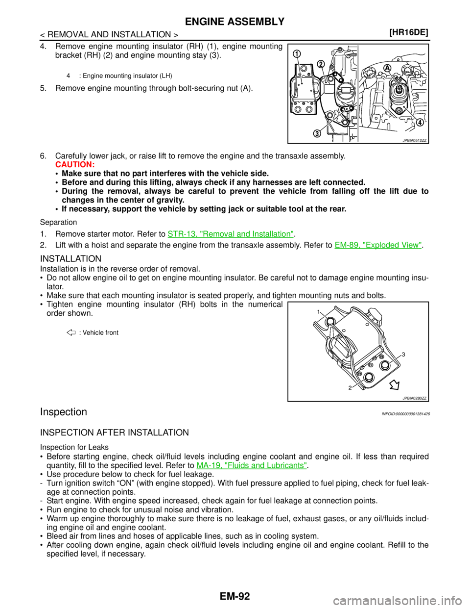
4. Remove engine mounting insulator (RH) (1), engine mounting
bracket (RH) (2) and engine mounting stay (3).
5. Remove engine mounting through bolt-securing nut (A).
6. Carefully lower jack, or raise lift to remove the engine and the transaxle assembly.
CAUTION:
Make sure that no part interferes with the vehicle side.
Before and during this lifting, always check if any harnesses are left connected.
During the removal, always be careful to prevent the vehicle from falling off the lift due to
changes in the center of gravity.
If necessary, support the vehicle by setting jack or suitable tool at the rear.
Separation
1. Remove starter motor. Refer to STR-13, "Removal and Installation".
2. Lift with a hoist and separate the engine from the transaxle assembly. Refer to EM-89, "
Exploded View".
INSTALLATION
Installation is in the reverse order of removal.
Do not allow engine oil to get on engine mounting insulator. Be careful not to damage engine mounting insu-
lator.
Make sure that each mounting insulator is seated properly, and tighten mounting nuts and bolts.
Tighten engine mounting insulator (RH) bolts in the numerical
order shown.
InspectionINFOID:0000000001381426
INSPECTION AFTER INSTALLATION
Inspection for Leaks
Before starting engine, check oil/fluid levels including engine coolant and engine oil. If less than required
quantity, fill to the specified level. Refer to MA-19, "
Fluids and Lubricants".
Use procedure below to check for fuel leakage.
- Turn ignition switch “ON” (with engine stopped). With fuel pressure applied to fuel piping, check for fuel leak-
age at connection points.
- Start engine. With engine speed increased, check again for fuel leakage at connection points.
Run engine to check for unusual noise and vibration.
Warm up engine thoroughly to make sure there is no leakage of fuel, exhaust gases, or any oil/fluids includ-
ing engine oil and engine coolant.
Bleed air from lines and hoses of applicable lines, such as in cooling system.
After cooling down engine, again check oil/fluid levels including engine oil and engine coolant. Refill to the
specified level, if necessary.
4 : Engine mounting insulator (LH)
JPBIA0512ZZ
: Vehicle front
JPBIA0280ZZ
Page 2856 of 5883
ENGINE ASSEMBLY
EM-209
< REMOVAL AND INSTALLATION >[MR18DE]
C
D
E
F
G
H
I
J
K
L
MA
EM
N
P O
24. Remove the intake manifold to prevent the hanging chain from interfering. Refer to EM-156, "Removal
and Installation".
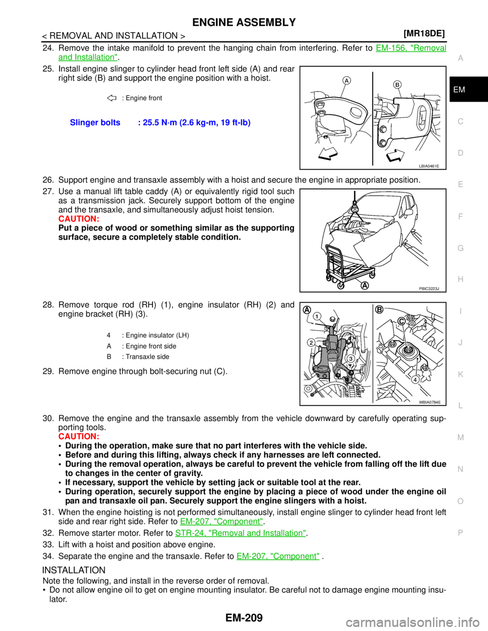
25. Install engine slinger to cylinder head front left side (A) and rear
right side (B) and support the engine position with a hoist.
26. Support engine and transaxle assembly with a hoist and secure the engine in appropriate position.
27. Use a manual lift table caddy (A) or equivalently rigid tool such
as a transmission jack. Securely support bottom of the engine
and the transaxle, and simultaneously adjust hoist tension.
CAUTION:
Put a piece of wood or something similar as the supporting
surface, secure a completely stable condition.
28. Remove torque rod (RH) (1), engine insulator (RH) (2) and
engine bracket (RH) (3).
29. Remove engine through bolt-securing nut (C).
30. Remove the engine and the transaxle assembly from the vehicle downward by carefully operating sup-
porting tools.
CAUTION:
During the operation, make sure that no part interferes with the vehicle side.
Before and during this lifting, always check if any harnesses are left connected.
During the removal operation, always be careful to prevent the vehicle from falling off the lift due
to changes in the center of gravity.
If necessary, support the vehicle by setting jack or suitable tool at the rear.
During operation, securely support the engine by placing a piece of wood under the engine oil
pan and transaxle oil pan. Securely support the engine slingers with a hoist.
31. When the engine hoisting is not performed simultaneously, install engine slinger to cylinder head front left
side and rear right side. Refer to EM-207, "
Component".
32. Remove starter motor. Refer to STR-24, "
Removal and Installation".
33. Lift with a hoist and position above engine.
34. Separate the engine and the transaxle. Refer to EM-207, "
Component" .
INSTALLATION
Note the following, and install in the reverse order of removal.
Do not allow engine oil to get on engine mounting insulator. Be careful not to damage engine mounting insu-
lator.
: Engine front
Slinger bolts : 25.5 N·m (2.6 kg-m, 19 ft-lb)
LBIA0461E
PBIC3223J
4 : Engine insulator (LH)
A : Engine front side
B : Transaxle side
WBIA0784E