2007 NISSAN TIIDA air vents
[x] Cancel search: air ventsPage 2712 of 5883
![NISSAN TIIDA 2007 Service Repair Manual CAMSHAFT
EM-65
< ON-VEHICLE REPAIR >[HR16DE]
C
D
E
F
G
H
I
J
K
L
MA
EM
N
P O
1. Install the oil filter (1).
The oil filter is assembled to the plug (3), and then install it to
the cylinder head.
2. NISSAN TIIDA 2007 Service Repair Manual CAMSHAFT
EM-65
< ON-VEHICLE REPAIR >[HR16DE]
C
D
E
F
G
H
I
J
K
L
MA
EM
N
P O
1. Install the oil filter (1).
The oil filter is assembled to the plug (3), and then install it to
the cylinder head.
2.](/manual-img/5/57395/w960_57395-2711.png)
CAMSHAFT
EM-65
< ON-VEHICLE REPAIR >[HR16DE]
C
D
E
F
G
H
I
J
K
L
MA
EM
N
P O
1. Install the oil filter (1).
The oil filter is assembled to the plug (3), and then install it to
the cylinder head.
2. Install intake valve timing control solenoid valve.
Insert it straightly into the cylinder head.
Tighten bolts after placing it completely.
3. Install valve lifter.
If it is reused, install in its original positions.
4. Put a matching mark for positioning the camshaft (INT) and the camshaft sprocket (INT) with the following
procedure.
NOTE:
It prevents the knock pin from engaging with the incorrect pin hole after installing the camshaft (INT) and
the camshaft sprocket (INT).
a. Put the matching marks (A) on a line extending from the knock
pin position of camshaft (INT) (1) front surface.
Put the marks on the visible position with the camshaft
sprocket installed. (Example shown)
b. Put the matching marks on a line extending from the knock pin
hole (B) position of camshaft sprocket (INT) (2). (Example
shown)
Put the marks on the visible position with it installed to the
camshaft.
5. Install camshaft.
Distinction between camshaft (INT and EXH) is performed with
the different shapes of rear end.
Install camshafts to the cylinder head so that knock pins (A) on
front end are positioned as shown.
NOTE:
Though camshaft does not stop at the portion as shown, for the
placement of cam nose, it is generally accepted camshaft is
placed for the same direction.
2: Washer
PBIC3695E
PBIC3696E
1 : Camshaft (EXH)
2 : Camshaft (INT)
A : Identification mark
PBIC3698E
1 : Camshaft (EXH)
2 : Camshaft (INT)
: Upper side
PBIC3699E
Page 2834 of 5883
![NISSAN TIIDA 2007 Service Repair Manual CAMSHAFT
EM-187
< ON-VEHICLE REPAIR >[MR18DE]
C
D
E
F
G
H
I
J
K
L
MA
EM
N
P O
Fuel tube and fuel injector assembly; Refer to EM-162.
Front cover, timing chain and related parts; Refer to EM-176
.
NISSAN TIIDA 2007 Service Repair Manual CAMSHAFT
EM-187
< ON-VEHICLE REPAIR >[MR18DE]
C
D
E
F
G
H
I
J
K
L
MA
EM
N
P O
Fuel tube and fuel injector assembly; Refer to EM-162.
Front cover, timing chain and related parts; Refer to EM-176
.](/manual-img/5/57395/w960_57395-2833.png)
CAMSHAFT
EM-187
< ON-VEHICLE REPAIR >[MR18DE]
C
D
E
F
G
H
I
J
K
L
MA
EM
N
P O
Fuel tube and fuel injector assembly; Refer to EM-162.
Front cover, timing chain and related parts; Refer to EM-176
.
7. Remove camshaft position sensor (PHASE) from camshaft bracket.
CAUTION:
Handle carefully to avoid dropping and shocks.
Never disassemble.
Never allow metal powder to adhere to magnetic part at sensor tip.
Never place sensor in a location where it is exposed to magnetism.
8. Put the matching mark (A) on the camshaft sprocket (INT) (2)
and the camshaft bracket (1) as shown.
NOTE:
It prevents the knock pin of the camshaft (INT) from engaging
with the incorrect pin hole when installing the camshaft sprocket
(INT).
9. Remove camshaft sprockets (INT) (1) and (EXH) (2).
Secure hexagonal part (A) of camshaft with a wrench. Loosen
camshaft sprocket bolts and remove camshaft sprocket.
CAUTION:
Never rotate crankshaft or camshaft while timing chain
is removed. It causes interference between valve and
piston.
Never loosen the bolts with securing anything other
than the camshaft hexagonal part or with tensioning the
timing chain.
10. Loosen bolts in reverse order as shown.
11. Cut liquid gasket by prying the position ( ) shown, and then
remove the camshaft bracket.
CAUTION:
Be careful not to damage the mating surface.
A more adhesive liquid gasket is applied compared to pre-
vious types when shipped, so it should not be forced off
the position not specified.
12. Remove camshafts.
: Engine front
PBIC3992J
PBIC3454J
: Engine front
PBIC3176J
: Engine front
PBIC3358J
Page 3241 of 5883

PRECAUTIONS
GI-47
< PRECAUTION >
C
D
E
F
G
H
I
J
K
L
MB
GI
N
O
P
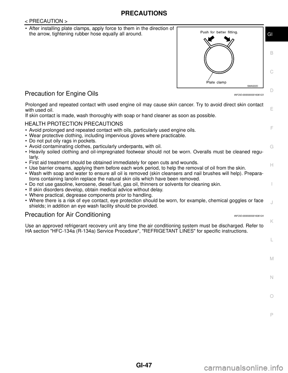
After installing plate clamps, apply force to them in the direction of
the arrow, tightening rubber hose equally all around.
Precaution for Engine OilsINFOID:0000000001606123
Prolonged and repeated contact with used engine oil may cause skin cancer. Try to avoid direct skin contact
with used oil.
If skin contact is made, wash thoroughly with soap or hand cleaner as soon as possible.
HEALTH PROTECTION PRECAUTIONS
Avoid prolonged and repeated contact with oils, particularly used engine oils.
Wear protective clothing, including impervious gloves where practicable.
Do not put oily rags in pockets.
Avoid contaminating clothes, particularly underpants, with oil.
Heavily soiled clothing and oil-impregnated footwear should not be worn. Overalls must be cleaned regu-
larly.
First aid treatment should be obtained immediately for open cuts and wounds.
Use barrier creams, applying them before each work period, to help the removal of oil from the skin.
Wash with soap and water to ensure all oil is removed (skin cleansers and nail brushes will help). Prepara-
tions containing lanolin replace the natural skin oils which have been removed.
Do not use gasoline, kerosene, diesel fuel, gas oil, thinners or solvents for cleaning skin.
If skin disorders develop, obtain medical advice without delay.
Where practical, degrease components prior to handling.
Where there is a risk of eye contact, eye protection should be worn, for example, chemical goggles or face
shields; in addition an eye wash facility should be provided.
Precaution for Air ConditioningINFOID:0000000001606124
Use an approved refrigerant recovery unit any time the air conditioning system must be discharged. Refer to
HA section "HFC-134a (R-134a) Service Procedure", "REFRIGETANT LINES" for specific instructions.
SMA022D
Page 3290 of 5883

HA-8
< PRECAUTION >
PRECAUTIONS
O-Ring Part Numbers and Specifications
CAUTION:
When replacing or cleaning refrigerant cycle components, observe the following.
When the compressor is removed, store it in the same position as it is when mounted on the vehicle.
Doing so will cause oil to enter the low-pressure chamber.
When connecting tubes, always use a torque wrench and a back-up wrench.
After disconnecting tubes, immediately plug all openings to prevent entry of dirt and moisture.
When installing an air conditioner in the vehicle, connect the pipes as the final stage of the opera-
tion. Do not remove the seal caps of pipes and other components until just before required for con-
nection.
Allow components stored in cool areas to warm to working area temperature before removing seal
caps. This prevents condensation from forming inside A/C components.
Thoroughly remove moisture from the refrigeration system before charging the refrigerant.
Always replace used O-rings.
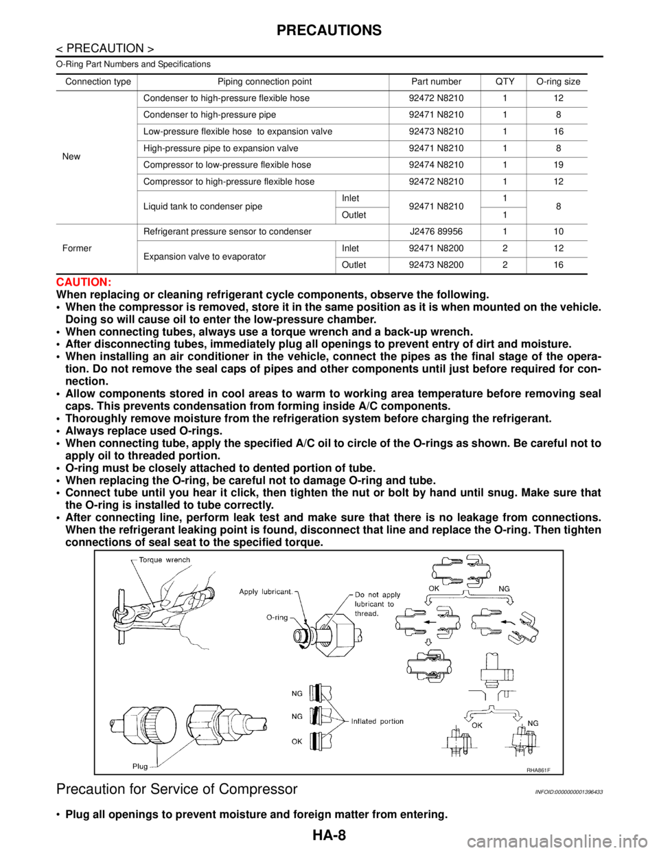
When connecting tube, apply the specified A/C oil to circle of the O-rings as shown. Be careful not to
apply oil to threaded portion.
O-ring must be closely attached to dented portion of tube.
When replacing the O-ring, be careful not to damage O-ring and tube.
Connect tube until you hear it click, then tighten the nut or bolt by hand until snug. Make sure that
the O-ring is installed to tube correctly.
After connecting line, perform leak test and make sure that there is no leakage from connections.
When the refrigerant leaking point is found, disconnect that line and replace the O-ring. Then tighten
connections of seal seat to the specified torque.
Precaution for Service of CompressorINFOID:0000000001396433
Plug all openings to prevent moisture and foreign matter from entering.
Connection type Piping connection point Part number QTY O-ring size
NewCondenser to high-pressure flexible hose 92472 N8210 1 12
Condenser to high-pressure pipe 92471 N8210 1 8
Low-pressure flexible hose to expansion valve 92473 N8210 1 16
High-pressure pipe to expansion valve 92471 N8210 1 8
Compressor to low-pressure flexible hose 92474 N8210 1 19
Compressor to high-pressure flexible hose 92472 N8210 1 12
Liquid tank to condenser pipeInlet
92471 N82101
8
Outlet 1
FormerRefrigerant pressure sensor to condenser J2476 89956 1 10
Expansion valve to evaporatorInlet 92471 N8200 2 12
Outlet 92473 N8200 2 16
RHA861F
Page 3306 of 5883

HA-24
< ON-VEHICLE MAINTENANCE >
FLUORESCENT LEAK DETECTOR
FLUORESCENT LEAK DETECTOR
Checking System for Leaks Using the Fluorescent Leak DetectorINFOID:0000000001396445
1. Check A/C system for leaks using the UV lamp and safety goggles J-42220 in a low sunlight area (area
without windows preferable). Illuminate all components, fittings and lines. The dye will appear as a bright
green/yellow area at the point of leakage. Fluorescent dye observed at the evaporator drain opening indi-
cates an evaporator core assembly (tubes, core or expansion valve) leak.
2. If the suspected area is difficult to see, use an adjustable mirror or wipe the area with a clean shop rag or
cloth, with the UV lamp for dye residue.
3. After the leak is repaired, remove any residual dye using dye cleaner J-43872 to prevent future misdiag-
nosis.
4. Perform a system performance check and verify the leak repair with an approved electronic refrigerant
leak detector.
NOTE:
Other gases in the work area or substances on the A/C components, for example, anti-freeze, windshield
washer fluid, solvents and oils, may falsely trigger the leak detector. Make sure the surfaces to be checked are
clean.
Clean with a dry cloth or blow off with shop air.
Do not allow the sensor tip of the detector to contact with any substance. This can also cause false readings
and may damage the detector.
Dye InjectionINFOID:0000000001396446
(This procedure is only necessary when recharging the system or when the compressor has seized and was
replaced.)
1. Check A/C system static (at rest) pressure. Pressure must be at least 345 kPa (3.45 bar, 3.52 kg/cm
2, 50
psi).
2. Pour one bottle (1/4 ounce / 7.4 cc) of the A/C refrigerant dye into the injector tool J-41459.
3. Connect the injector tool to the A/C low-pressure side service fitting.
4. Start engine and switch A/C ON.
5. When the A/C operating (compressor running), inject one bottle (1/4 ounce / 7.4 cc) of fluorescent dye
through the low-pressure service valve using dye injector tool J-41459 (refer to the manufacture’s operat-
ing instructions).
6. With the engine still running, disconnect the injector tool from the service fitting.
CAUTION:
Be careful the A/C system or replacing a component, pour the dye directly into the open system
connection and proceed with the service procedures.
7. Operate the A/C system for a minimum of 20 minutes to mix the dye with the system oil. Depending on the
leak size, operating conditions and location of the leak, it may take from minutes to days for the dye to
penetrate a leak and become visible.
Page 3439 of 5883
![NISSAN TIIDA 2007 Service Repair Manual HAC-106
< COMPONENT DIAGNOSIS >[AUTO AIR CONDITIONER (W/O NAVI)]
MODE DOOR MOTOR
COMPONENT DIAGNOSIS
MODE DOOR MOTOR
System DescriptionINFOID:0000000001547404
SYSTEM DESCRIPTION
Component Parts
Mode d NISSAN TIIDA 2007 Service Repair Manual HAC-106
< COMPONENT DIAGNOSIS >[AUTO AIR CONDITIONER (W/O NAVI)]
MODE DOOR MOTOR
COMPONENT DIAGNOSIS
MODE DOOR MOTOR
System DescriptionINFOID:0000000001547404
SYSTEM DESCRIPTION
Component Parts
Mode d](/manual-img/5/57395/w960_57395-3438.png)
HAC-106
< COMPONENT DIAGNOSIS >[AUTO AIR CONDITIONER (W/O NAVI)]
MODE DOOR MOTOR
COMPONENT DIAGNOSIS
MODE DOOR MOTOR
System DescriptionINFOID:0000000001547404
SYSTEM DESCRIPTION
Component Parts
Mode door control system components are:
Front air control
Mode door motor
In-vehicle sensor
Ambient sensor
Sunload sensor
System Operation
The front air control receives data from each of the sensors. When a drive signal is input from front air control
to door motor, a step motor built into the door motor rotates according to the drive signal, and then stops at the
position of target door.
Mode door changes to manual select mode by pressing MODE/DEF switch of the controller. That allows mode
door to be fixed.
Pressing AUTO switch allows automatic control by front air control, and mode door is fixed in the FOOT posi-
tion by pressing OFF switch.
During automatic operation of mode door, mode door position (VENT, B/L, FOOT) is selected according to the
temperature of discharge air calculated by front air control based on the target opening angle of air mix door
and the amount of sunload. And only when ambient temperature is extremely low with the mode door in the
FOOT position, D/F is selected and prevents windshield fogging.
AWIIA0290GB
Page 3469 of 5883
![NISSAN TIIDA 2007 Service Repair Manual HAC-136
< COMPONENT DIAGNOSIS >[AUTO AIR CONDITIONER (W/O NAVI)]
SUNLOAD SENSOR
SUNLOAD SENSOR
System DescriptionINFOID:0000000001547443
COMPONENT DESCRIPTION
Sunload Sensor
The sunload sensor (1) is NISSAN TIIDA 2007 Service Repair Manual HAC-136
< COMPONENT DIAGNOSIS >[AUTO AIR CONDITIONER (W/O NAVI)]
SUNLOAD SENSOR
SUNLOAD SENSOR
System DescriptionINFOID:0000000001547443
COMPONENT DESCRIPTION
Sunload Sensor
The sunload sensor (1) is](/manual-img/5/57395/w960_57395-3468.png)
HAC-136
< COMPONENT DIAGNOSIS >[AUTO AIR CONDITIONER (W/O NAVI)]
SUNLOAD SENSOR
SUNLOAD SENSOR
System DescriptionINFOID:0000000001547443
COMPONENT DESCRIPTION
Sunload Sensor
The sunload sensor (1) is located on the instrument upper mask. It
detects sunload entering through windshield by means of a photo
diode. The sensor converts the sunload into a current value which is
then input into the front air control.
SUNLOAD INPUT PROCESS
The front air control also includes a processing circuit which averages the variations in detected sunload over
a period of time. This prevents drastic swings in the ATC system operation due to small or quick variations in
detected sunload.
For example, consider driving along a road bordered by an occasional group of large trees. The sunload
detected by the sunload sensor will vary whenever the trees obstruct the sunlight. The processing circuit aver-
ages the detected sunload over a period of time, so that the (insignificant) effect of the trees momentarily
obstructing the sunlight does not cause any change in the ATC system operation. On the other hand, shortly
after entering a long tunnel, the system will recognize the change in sunload, and the system will react accord-
ingly.
Sunload Sensor Diagnosis ProcedureINFOID:0000000001547442
DIAGNOSTIC PROCEDURE FOR SUNLOAD SENSOR
SYMPTOM: Sunload sensor circuit is open or shorted. (25 or AUTO25
is indicated on front air control as a result of performing self-diagno-
sis STEP-2.)
1.CHECK VOLTAGE BETWEEN SUNLOAD SENSOR AND GROUND
1. Turn ignition switch OFF.
2. Disconnect sunload sensor connector M94.
3. Turn ignition switch ON.
4. Check voltage between sunload sensor harness connector M94
terminal 1 and ground.
Is the inspection result normal?
SJIA0819E
AWIIA0312GB
Te r m i n a l s
Voltag e
(Approx.) (+) (−)
Connector Terminal
Ground
Sunload sensor: M94 1 5V
SJIA0821E
Page 3552 of 5883
![NISSAN TIIDA 2007 Service Repair Manual MODE DOOR MOTOR
HAC-219
< COMPONENT DIAGNOSIS >[AUTO AIR CONDITIONER (W/NAVI)]
C
D
E
F
G
H
J
K
L
MA
B
HAC
N
O
P
COMPONENT DIAGNOSIS
MODE DOOR MOTOR
System DescriptionINFOID:0000000001547326
SYSTEM DES NISSAN TIIDA 2007 Service Repair Manual MODE DOOR MOTOR
HAC-219
< COMPONENT DIAGNOSIS >[AUTO AIR CONDITIONER (W/NAVI)]
C
D
E
F
G
H
J
K
L
MA
B
HAC
N
O
P
COMPONENT DIAGNOSIS
MODE DOOR MOTOR
System DescriptionINFOID:0000000001547326
SYSTEM DES](/manual-img/5/57395/w960_57395-3551.png)
MODE DOOR MOTOR
HAC-219
< COMPONENT DIAGNOSIS >[AUTO AIR CONDITIONER (W/NAVI)]
C
D
E
F
G
H
J
K
L
MA
B
HAC
N
O
P
COMPONENT DIAGNOSIS
MODE DOOR MOTOR
System DescriptionINFOID:0000000001547326
SYSTEM DESCRIPTION
Component Parts
Mode door control system components are:
Front air control
Mode door motor
In-vehicle sensor
Ambient sensor
Sunload sensor
System Operation
The front air control receives data from each of the sensors. When a drive signal is input from front air control
to door motor, a step motor built into the door motor rotates according to the drive signal, and then stops at the
position of target door.
Mode door changes to manual select mode by turning mode control dial of the controller. That allows mode
door to be fixed.
Pressing AUTO switch allows automatic control by front air control, and mode door is fixed in the FOOT posi-
tion by pressing OFF switch.
During automatic operation of mode door, mode door position (VENT, B/L, FOOT) is selected according to the
temperature of blow-off wind calculated by front air control based on the target opening angle of air mix door
and the amount of solar radiation. And only when ambient temperature is extremely low with the mode door in
the FOOT position, D/F is selected and prevents windshield fogging.
AWIIA0333GB