2007 NISSAN TIIDA starter
[x] Cancel search: starterPage 1869 of 5883
EC-520
< COMPONENT DIAGNOSIS >[HR16DE (WITHOUT EURO-OBD)]
P0340 CMP SENSOR (PHASE)
P0340 CMP SENSOR (PHASE)
DescriptionINFOID:0000000001693299
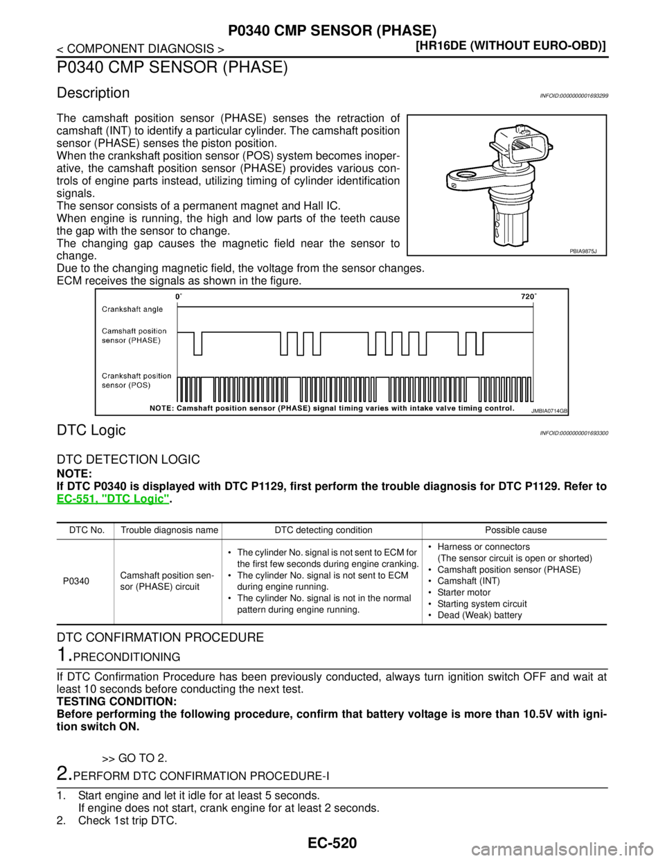
The camshaft position sensor (PHASE) senses the retraction of
camshaft (INT) to identify a particular cylinder. The camshaft position
sensor (PHASE) senses the piston position.
When the crankshaft position sensor (POS) system becomes inoper-
ative, the camshaft position sensor (PHASE) provides various con-
trols of engine parts instead, utilizing timing of cylinder identification
signals.
The sensor consists of a permanent magnet and Hall IC.
When engine is running, the high and low parts of the teeth cause
the gap with the sensor to change.
The changing gap causes the magnetic field near the sensor to
change.
Due to the changing magnetic field, the voltage from the sensor changes.
ECM receives the signals as shown in the figure.
DTC LogicINFOID:0000000001693300
DTC DETECTION LOGIC
NOTE:
If DTC P0340 is displayed with DTC P1129, first perform the trouble diagnosis for DTC P1129. Refer to
EC-551, "
DTC Logic".
DTC CONFIRMATION PROCEDURE
1.PRECONDITIONING
If DTC Confirmation Procedure has been previously conducted, always turn ignition switch OFF and wait at
least 10 seconds before conducting the next test.
TESTING CONDITION:
Before performing the following procedure, confirm that battery voltage is more than 10.5V with igni-
tion switch ON.
>> GO TO 2.
2.PERFORM DTC CONFIRMATION PROCEDURE-I
1. Start engine and let it idle for at least 5 seconds.
If engine does not start, crank engine for at least 2 seconds.
2. Check 1st trip DTC.
PBIA9875J
JMBIA0714GB
DTC No. Trouble diagnosis name DTC detecting condition Possible cause
P0340Camshaft position sen-
sor (PHASE) circuit The cylinder No. signal is not sent to ECM for
the first few seconds during engine cranking.
The cylinder No. signal is not sent to ECM
during engine running.
The cylinder No. signal is not in the normal
pattern during engine running. Harness or connectors
(The sensor circuit is open or shorted)
Camshaft position sensor (PHASE)
Camshaft (INT)
Starter motor
Starting system circuit
Dead (Weak) battery
Page 1870 of 5883
P0340 CMP SENSOR (PHASE)
EC-521
< COMPONENT DIAGNOSIS >[HR16DE (WITHOUT EURO-OBD)]
C
D
E
F
G
H
I
J
K
L
MA
EC
N
P O
Is 1st trip DTC detected?
YES >> Go to EC-521, "Diagnosis Procedure".
NO >> GO TO 3.
3.PERFORM DTC CONFIRMATION PROCEDURE-I
1. Maintaining engine speed at more than 800 rpm for at least 5 seconds.
2. Check 1st trip DTC.
Is 1st trip DTC detected?
YES >> Go to EC-521, "Diagnosis Procedure".
NO >> INSPECTION END
Diagnosis ProcedureINFOID:0000000001693301
1.CHECK STARTING SYSTEM
Turn ignition switch to START position.
Does the engine turn over? Does the starter motor operate?
YES >> GO TO 2.
NO >> Check starting system.
2.CHECK GROUND CONNECTION
1. Turn ignition switch OFF.
2. Check ground connection E15. Refer to Ground Inspection in GI-58, "
Circuit Inspection".
Is the inspection result normal?
YES >> GO TO 3.
NO >> Repair or replace ground connection.
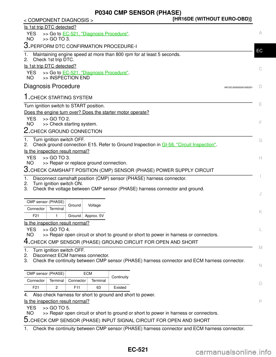
3.CHECK CAMSHAFT POSITION (CMP) SENSOR (PHASE) POWER SUPPLY CIRCUIT
1. Disconnect camshaft position (CMP) sensor (PHASE) harness connector.
2. Turn ignition switch ON.
3. Check the voltage between CMP sensor (PHASE) harness connector and ground.
Is the inspection result normal?
YES >> GO TO 4.
NO >> Repair open circuit or short to ground or short to power in harness or connectors.
4.CHECK CMP SENSOR (PHASE) GROUND CIRCUIT FOR OPEN AND SHORT
1. Turn ignition switch OFF.
2. Disconnect ECM harness connector.
3. Check the continuity between CMP sensor (PHASE) harness connector and ECM harness connector.
4. Also check harness for short to ground and short to power.
Is the inspection result normal?
YES >> GO TO 5.
NO >> Repair open circuit or short to ground or short to power in harness or connectors.
5.CHECK CMP SENSOR (PHASE) INPUT SIGNAL CIRCUIT FOR OPEN AND SHORT
1. Check the continuity between CMP sensor (PHASE) harness connector and ECM harness connector.
CMP sensor (PHASE)
Ground Voltage
Connector Terminal
F21 1 Ground Approx. 5V
CMP sensor (PHASE) ECM
Continuity
Connector Terminal Connector Terminal
F21 2 F11 63 Existed
Page 2021 of 5883
EC-672
< SYMPTOM DIAGNOSIS >[HR16DE (WITHOUT EURO-OBD)]
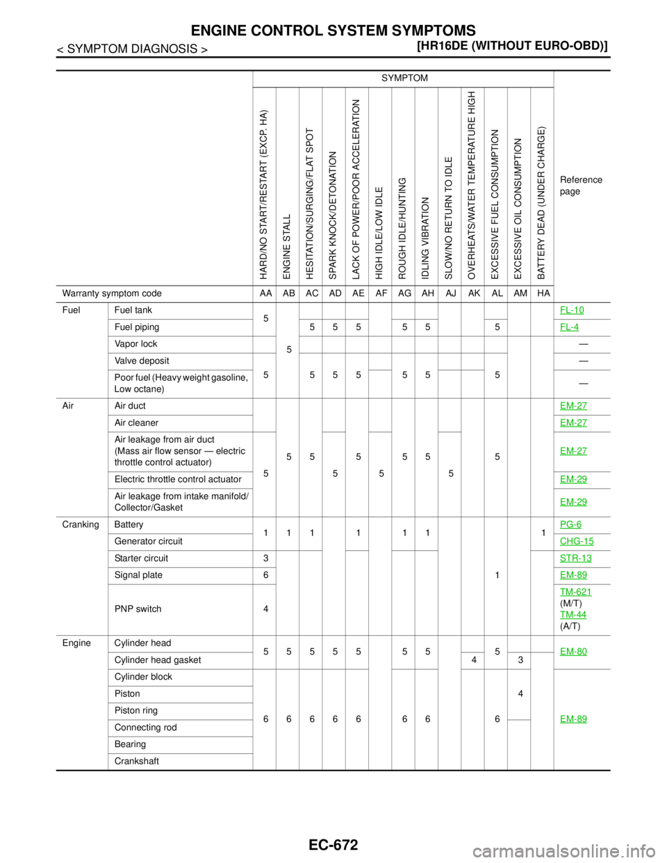
ENGINE CONTROL SYSTEM SYMPTOMS
SYMPTOM
Reference
page
HARD/NO START/RESTART (EXCP. HA)
ENGINE STALL
HESITATION/SURGING/FLAT SPOT
SPARK KNOCK/DETONATION
LACK OF POWER/POOR ACCELERATION
HIGH IDLE/LOW IDLE
ROUGH IDLE/HUNTING
IDLING VIBRATION
SLOW/NO RETURN TO IDLE
OVERHEATS/WATER TEMPERATURE HIGH
EXCESSIVE FUEL CONSUMPTION
EXCESSIVE OIL CONSUMPTION
BATTERY DEAD (UNDER CHARGE)
Warranty symptom code AA AB AC AD AE AF AG AH AJ AK AL AM HA
Fuel Fuel tank
5
5FL-10
Fuel piping 5 5 5 5 5 5FL-4
Va p o r l o c k—
Valve deposit
5 555 55 5—
Poor fuel (Heavy weight gasoline,
Low octane)—
Air Air duct
55555 5EM-27
Air cleanerEM-27
Air leakage from air duct
(Mass air flow sensor — electric
throttle control actuator)
5555EM-27
Electric throttle control actuatorEM-29
Air leakage from intake manifold/
Collector/GasketEM-29
Cranking Battery
111111
11PG-6
Generator circuitCHG-15
Starter circuit 3STR-13
Signal plate 6EM-89
PNP switch 4TM-621
(M/T)
TM-44
(A/T)
Engine Cylinder head
55555 55 5EM-80
Cylinder head gasket 4 3
Cylinder block
66666 66 64
EM-89
Piston
Piston ring
Connecting rod
Bearing
Crankshaft
Page 2125 of 5883
EC-776
< FUNCTION DIAGNOSIS >[MR18DE]
ON BOARD DIAGNOSTIC (OBD) SYSTEM
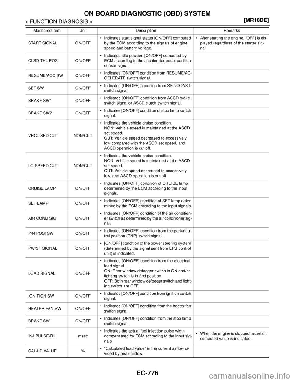
START SIGNAL ON/OFF Indicates start signal status [ON/OFF] computed
by the ECM according to the signals of engine
speed and battery voltage. After starting the engine, [OFF] is dis-
played regardless of the starter sig-
nal.
CLSD THL POS ON/OFF Indicates idle position [ON/OFF] computed by
ECM according to the accelerator pedal position
sensor signal.
RESUME/ACC SW ON/OFF Indicates [ON/OFF] condition from RESUME/AC-
CELERATE switch signal.
SET SW ON/OFF Indicates [ON/OFF] condition from SET/COAST
switch signal.
BRAKE SW1 ON/OFF Indicates [ON/OFF] condition from ASCD brake
switch signal or ASCD clutch switch signal.
BRAKE SW2 ON/OFF Indicates [ON/OFF] condition of stop lamp switch
signal.
VHCL SPD CUT NON/CUT Indicates the vehicle cruise condition.
NON: Vehicle speed is maintained at the ASCD
set speed.
CUT: Vehicle speed decreased to excessively
low compared with the ASCD set speed, and
ASCD operation is cut off.
LO SPEED CUT NON/CUT Indicates the vehicle cruise condition.
NON: Vehicle speed is maintained at the ASCD
set speed.
CUT: Vehicle speed decreased to excessively
low, and ASCD operation is cut off.
CRUISE LAMP ON/OFF Indicates [ON/OFF] condition of CRUISE lamp
determined by the ECM according to the input
signals.
SET LAMP ON/OFF Indicates [ON/OFF] condition of SET lamp deter-
mined by the ECM according to the input signals.
AIR COND SIG ON/OFF Indicates [ON/OFF] condition of the air condition-
er switch as determined by the air conditioner sig-
nal.
P/N POSI SW ON/OFF Indicates [ON/OFF] condition from the park/neu-
tral position (PNP) switch signal.
PW/ST SIGNAL ON/OFF [ON/OFF] condition of the power steering system
(determined by the signal sent from EPS control
unit) is indicated.
LOAD SIGNAL ON/OFF Indicates [ON/OFF] condition from the electrical
load signal.
ON: Rear window defogger switch is ON and/or
lighting switch is in 2nd position.
OFF: Both rear window defogger switch and light-
ing switch are OFF.
IGNITION SW ON/OFF Indicates [ON/OFF] condition from ignition switch
signal.
HEATER FAN SW ON/OFF Indicates [ON/OFF] condition from the heater fan
switch signal.
BRAKE SW ON/OFF Indicates [ON/OFF] condition from the stop lamp
switch signal.
INJ PULSE-B1 msec Indicates the actual fuel injection pulse width
compensated by ECM according to the input sig-
nals. When the engine is stopped, a certain
computed value is indicated.
CAL/LD VALUE % “Calculated load value” in the current airflow di-
vided by peak airflow. Monitored item Unit Description Remarks
Page 2215 of 5883
EC-866
< COMPONENT DIAGNOSIS >[MR18DE]
P0340 CMP SENSOR (PHASE)
P0340 CMP SENSOR (PHASE)
DescriptionINFOID:0000000001161833
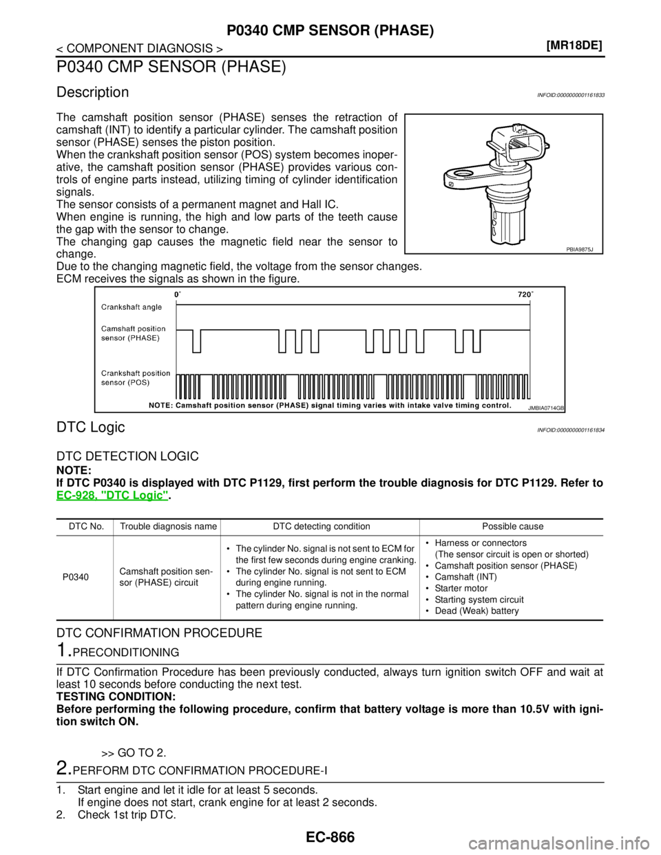
The camshaft position sensor (PHASE) senses the retraction of
camshaft (INT) to identify a particular cylinder. The camshaft position
sensor (PHASE) senses the piston position.
When the crankshaft position sensor (POS) system becomes inoper-
ative, the camshaft position sensor (PHASE) provides various con-
trols of engine parts instead, utilizing timing of cylinder identification
signals.
The sensor consists of a permanent magnet and Hall IC.
When engine is running, the high and low parts of the teeth cause
the gap with the sensor to change.
The changing gap causes the magnetic field near the sensor to
change.
Due to the changing magnetic field, the voltage from the sensor changes.
ECM receives the signals as shown in the figure.
DTC LogicINFOID:0000000001161834
DTC DETECTION LOGIC
NOTE:
If DTC P0340 is displayed with DTC P1129, first perform the trouble diagnosis for DTC P1129. Refer to
EC-928, "
DTC Logic".
DTC CONFIRMATION PROCEDURE
1.PRECONDITIONING
If DTC Confirmation Procedure has been previously conducted, always turn ignition switch OFF and wait at
least 10 seconds before conducting the next test.
TESTING CONDITION:
Before performing the following procedure, confirm that battery voltage is more than 10.5V with igni-
tion switch ON.
>> GO TO 2.
2.PERFORM DTC CONFIRMATION PROCEDURE-I
1. Start engine and let it idle for at least 5 seconds.
If engine does not start, crank engine for at least 2 seconds.
2. Check 1st trip DTC.
PBIA9875J
JMBIA0714GB
DTC No. Trouble diagnosis name DTC detecting condition Possible cause
P0340Camshaft position sen-
sor (PHASE) circuit The cylinder No. signal is not sent to ECM for
the first few seconds during engine cranking.
The cylinder No. signal is not sent to ECM
during engine running.
The cylinder No. signal is not in the normal
pattern during engine running. Harness or connectors
(The sensor circuit is open or shorted)
Camshaft position sensor (PHASE)
Camshaft (INT)
Starter motor
Starting system circuit
Dead (Weak) battery
Page 2216 of 5883
P0340 CMP SENSOR (PHASE)
EC-867
< COMPONENT DIAGNOSIS >[MR18DE]
C
D
E
F
G
H
I
J
K
L
MA
EC
N
P O
Is 1st trip DTC detected?
YES >> Go to EC-867, "Diagnosis Procedure".
NO >> GO TO 3.
3.PERFORM DTC CONFIRMATION PROCEDURE-I
1. Maintaining engine speed at more than 800 rpm for at least 5 seconds.
2. Check 1st trip DTC.
Is 1st trip DTC detected?
YES >> Go to EC-867, "Diagnosis Procedure".
NO >> INSPECTION END
Diagnosis ProcedureINFOID:0000000001161835
1.CHECK STARTING SYSTEM
Turn ignition switch to START position.
Does the engine turn over? Does the starter motor operate?
YES >> GO TO 2.
NO >> Check starting system.
2.CHECK GROUND CONNECTION
1. Turn ignition switch OFF.
2. Check ground connection E15. Refer to Ground Inspection in GI-58, "
Circuit Inspection".
Is the inspection result normal?
YES >> GO TO 3.
NO >> Repair or replace ground connection.
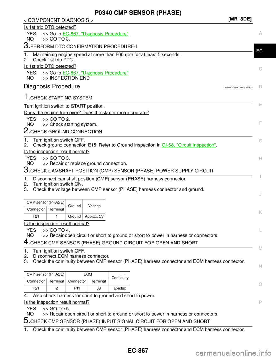
3.CHECK CAMSHAFT POSITION (CMP) SENSOR (PHASE) POWER SUPPLY CIRCUIT
1. Disconnect camshaft position (CMP) sensor (PHASE) harness connector.
2. Turn ignition switch ON.
3. Check the voltage between CMP sensor (PHASE) harness connector and ground.
Is the inspection result normal?
YES >> GO TO 4.
NO >> Repair open circuit or short to ground or short to power in harness or connectors.
4.CHECK CMP SENSOR (PHASE) GROUND CIRCUIT FOR OPEN AND SHORT
1. Turn ignition switch OFF.
2. Disconnect ECM harness connector.
3. Check the continuity between CMP sensor (PHASE) harness connector and ECM harness connector.
4. Also check harness for short to ground and short to power.
Is the inspection result normal?
YES >> GO TO 5.
NO >> Repair open circuit or short to ground or short to power in harness or connectors.
5.CHECK CMP SENSOR (PHASE) INPUT SIGNAL CIRCUIT FOR OPEN AND SHORT
1. Check the continuity between CMP sensor (PHASE) harness connector and ECM harness connector.
CMP sensor (PHASE)
Ground Voltage
Connector Terminal
F21 1 Ground Approx. 5V
CMP sensor (PHASE) ECM
Continuity
Connector Terminal Connector Terminal
F21 2 F11 63 Existed
Page 2375 of 5883
EC-1026
< SYMPTOM DIAGNOSIS >[MR18DE]
ENGINE CONTROL SYSTEM
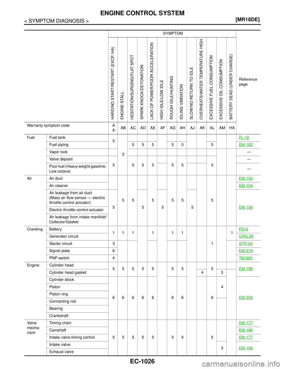
SYMPTOM
Reference
page
HARD/NO START/RESTART (EXCP. HA)
ENGINE STALL
HESITATION/SURGING/FLAT SPOT
SPARK KNOCK/DETONATION
LACK OF POWER/POOR ACCELERATION
HIGH IDLE/LOW IDLE
ROUGH IDLE/HUNTING
IDLING VIBRATION
SLOW/NO RETURN TO IDLE
OVERHEATS/WATER TEMPERATURE HIGH
EXCESSIVE FUEL CONSUMPTION
EXCESSIVE OIL CONSUMPTION
BATTERY DEAD (UNDER CHARGE)
Warranty symptom code A
AAB AC AD AE AF AG AH AJ AK AL AM HA
Fuel Fuel tank
5
5FL-10
Fuel piping 555 55 5EM-162
Va p o r l o c k—
Valve deposit
5 555 55 5—
Poor fuel (Heavy weight gasoline,
Low octane)—
Air Air duct
55555 5EM-154
Air cleanerEM-154
Air leakage from air duct
(Mass air flow sensor — electric
throttle control actuator)
555 5EM-156
Electric throttle control actuator
Air leakage from intake manifold/
Collector/Gasket
Cranking Battery
111111
11PG-6
Generator circuitCHG-29
Starter circuit 3STR-24
Signal plate 6EM-219
PNP switch 4TM-665
Engine Cylinder head
55555 55 5EM-198
Cylinder head gasket 4 3
Cylinder block
66666 66 64
EM-200
Piston
Piston ring
Connecting rod
Bearing
Crankshaft
Va l v e
mecha-
nismTiming chain
55555 55 5EM-177
CamshaftEM-186
Intake valve timing controlEM-177
Intake valve
3EM-198
Exhaust valve
Page 2402 of 5883
INSPECTION AND ADJUSTMENT
EC-1053
< BASIC INSPECTION >[K9K]
C
D
E
F
G
H
I
J
K
L
MA
EC
N
P O
YES >> GO TO 2.
NO >> Replace malfunctioning fuel injector.
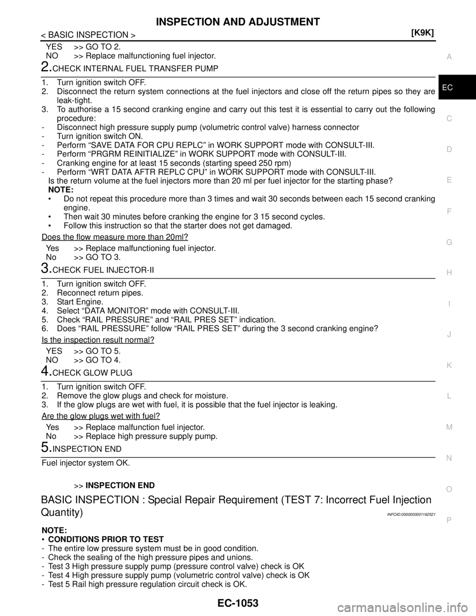
2.CHECK INTERNAL FUEL TRANSFER PUMP
1. Turn ignition switch OFF.
2. Disconnect the return system connections at the fuel injectors and close off the return pipes so they are
leak-tight.
3. To authorise a 15 second cranking engine and carry out this test it is essential to carry out the following
procedure:
- Disconnect high pressure supply pump (volumetric control valve) harness connector
- Turn ignition switch ON.
- Perform “SAVE DATA FOR CPU REPLC” in WORK SUPPORT mode with CONSULT-III.
- Perform “PRGRM REINITIALIZE” in WORK SUPPORT mode with CONSULT-III.
- Cranking engine for at least 15 seconds (starting speed 250 rpm)
- Perform “WRT DATA AFTR REPLC CPU” in WORK SUPPORT mode with CONSULT-III.
Is the return volume at the fuel injectors more than 20 ml per fuel injector for the starting phase?
NOTE:
Do not repeat this procedure more than 3 times and wait 30 seconds between each 15 second cranking
engine.
Then wait 30 minutes before cranking the engine for 3 15 second cycles.
Follow this instruction so that the starter does not get damaged.
Does the flow measure more than 20ml?
Yes >> Replace malfunctioning fuel injector.
No >> GO TO 3.
3.CHECK FUEL INJECTOR-II
1. Turn ignition switch OFF.
2. Reconnect return pipes.
3. Start Engine.
4. Select “DATA MONITOR” mode with CONSULT-III.
5. Check “RAIL PRESSURE” and “RAIL PRES SET” indication.
6. Does “RAIL PRESSURE” follow “RAIL PRES SET” during the 3 second cranking engine?
Is the inspection result normal?
YES >> GO TO 5.
NO >> GO TO 4.
4.CHECK GLOW PLUG
1. Turn ignition switch OFF.
2. Remove the glow plugs and check for moisture.
3. If the glow plugs are wet with fuel, it is possible that the fuel injector is leaking.
Are the glow plugs wet with fuel?
Yes >> Replace malfunction fuel injector.
No >> Replace high pressure supply pump.
5.INSPECTION END
Fuel injector system OK.
>>INSPECTION END
BASIC INSPECTION : Special Repair Requirement (TEST 7: Incorrect Fuel Injection
Quantity)
INFOID:0000000001162521
NOTE:
CONDITIONS PRIOR TO TEST
- The entire low pressure system must be in good condition.
- Check the sealing of the high pressure pipes and unions.
- Test 3 High pressure supply pump (pressure control valve) check is OK
- Test 4 High pressure supply pump (volumetric control valve) check is OK
- Test 5 Rail high pressure regulation circuit check is OK.