2007 NISSAN TIIDA starter
[x] Cancel search: starterPage 4441 of 5883

PCS
IPDM E/R (INTELLIGENT POWER DISTRIBUTION MODULE ENGINE ROOM)
PCS-27
< ECU DIAGNOSIS >[IPDM E/R]
C
D
E
F
G
H
I
J
K
L B A
O
P N If No CAN Communication Is Available With BCM
IGNITION RELAY MALFUNCTION DETECTION FUNCTION
IPDM E/R monitors the voltage at the contact circuit and excitation coil circuit of the ignition relay inside it.
IPDM E/R judges the ignition relay error if the voltage differs between the contact circuit and the excitation
coil circuit.
If the ignition relay cannot turn OFF due to contact seizure, it activates the tail lamp relay for 10 minutes to
alert the user to the ignition relay malfunction when the ignition switch is turned OFF.
NOTE:
The tail lamp turns OFF when the ignition switch is turned ON.
FRONT WIPER CONTROL
IPDM E/R detects front wiper stop position by a front wiper auto stop signal.
When a front wiper auto stop signal is in the conditions listed below, IPDM E/R stops power supply to wiper
after repeating a front wiper 10 second activation and 20 second stop five times.
NOTE:
This operation status can be confirmed on the IPDM E/R “DATA MONITOR” that displays “Block” for the item
“WIP PROT” while the wiper is stopped.
STARTER MOTOR PROTECTION FUNCTION
IPDM E/R turns OFF the starter control relay to protect the starter motor when the starter control relay remains
active for 90 seconds.
Control part Fail-safe in operation
Cooling fan Turns ON the cooling fan relay when the ignition switch is turned ON
Turns OFF the cooling fan relay when the ignition switch is turned OFF
Control part Fail-safe in operation
Headlamp Turns ON the headlamp low relay when the ignition switch is turned ON
Turns OFF the headlamp low relay when the ignition switch is turned OFF
Headlamp high relay OFF
Parking lamps
License plate lamps
Tail lamps Turns ON the tail lamp relay when the ignition switch is turned ON
Turns OFF the tail lamp relay when the ignition switch is turned OFF
Front wiper The status just before activation of fail-safe control is maintained until the ignition
switch is turned OFF while the front wiper is operating at LO or HI speed.
The wiper is operated at LO speed until the ignition switch is turned OFF if the fail-
safe control is activated while the front wiper is set in the INT mode and the front wiper
motor is operating.
Rear window defogger Rear window defogger relay OFF
A/C compressor A/C relay OFF
Front fog lamps Front fog lamp relay OFF
Ignition switch Ignition relay Tail lamp relay
ON ON —
OFF OFF —
Ignition switch Front wiper switch Auto stop signal
ONOFFFront wiper stop position signal cannot be
input 10 seconds.
ON The signal does not change for 10 seconds.
Page 4633 of 5883

SEC-8
< FUNCTION DIAGNOSIS >[WITH INTELLIGENT KEY SYSTEM]
INTELLIGENT KEY SYSTEM/ENGINE START FUNCTION
FUNCTION DIAGNOSIS
INTELLIGENT KEY SYSTEM/ENGINE START FUNCTION
System DiagramINFOID:0000000001404034
System DescriptionINFOID:0000000001404035
INPUT/OUTPUT SIGNAL CHART
Intelligent Key Unit
IPDM E/R
BCM
SYSTEM DESCRIPTION
The engine start function of Intelligent Key system is a system that makes it possible to start and stop the
engine without using the key. It verifies the electronic ID using two-way communications when pressing the
ignition knob switch while carrying the Intelligent Key, which operates based on the results of electronic ID
verification for Intelligent Key using two-way communications between the Intelligent Key and the vehicle.
NOTE:
The driver should carry the Intelligent Key at all times.
Switch/Input signalInput signal to
Intelligent Key unit Intelligent Key unit
functionActuator/Output signal
Key switchMechanical key
(insert/remove)
Engine start function KEY warning lamp/buzzer
Steering lock unit
Starter relay request (to IPDM E/
R)
Inside key antenna
(Instrument center, console, rear
seat)
Key interlock solenoid Ignition knob switchIgnition knob
(push/release)
Steering lock unitSteering lock
(lock/unlock)
Inside key antenna
(Instrument center, console, rear
seat)Intelligent key
(inside antenna detection
area or not.)
Switch/Input signalInput signal to
IPDM E/R IPDM E/R function Actuator/Output signal
Park/neutral position switch (only
for A/T models)P,N range Engine start function Starter relay
Starter motor
Switch/Input signalInput signal to
BCM BCM function Actuator/Output signal
Key switchMechanical key
(insert/remove)Engine start function Inside key antenna
(Instrument center, console, rear
seat)
MIIB0785E
Page 4634 of 5883

INTELLIGENT KEY SYSTEM/ENGINE START FUNCTION
SEC-9
< FUNCTION DIAGNOSIS >[WITH INTELLIGENT KEY SYSTEM]
C
D
E
F
G
H
I
J
L
MA
B
SEC
N
O
P
Intelligent Key has 2 IDs (for Intelligent Key and for NATS). It can perform the door lock/unlock operation and
the engine start operation when the registered Intelligent Key is carried.
When the Intelligent Key battery is discharged, it can be used as emergency back-up by inserting the
mechanical key set in the Intelligent Key to the ignition key cylinder. At that time, perform the NATS ID verifi-
cation. If it is used when the Intelligent Key is carried, perform the Intelligent Key ID verification.
If the ID is successfully verified, and when the ignition knob switch is pressed, steering lock will be released
and initiating the engine will be possible.
The door lock/unlock operation can be performed when the Intelligent Key battery is discharged, by operat-
ing the driver door key cylinder using the mechanical key set in the Intelligent Key.
Up to 4 Intelligent Keys can be registered (including the standard Intelligent Key) on request from the owner.
NOTE:
Refer to XX-XX, "*****"
for any functions other than engine start function of Intelligent Key system.
PRECAUTIONS FOR INTELLIGENT KEY SYSTEM
In the Intelligent Key system, the transponder [the chip for NATS ID verification] is integrated into the
Intelligent Key. (For non-Intelligent Key systems, it is integrated into the mechanical key.) Therefore,
the mechanical key cannot perform the ID verification, and thus it cannot start the engine. Instead,
the NATS ID verification can be performed by inserting the mechanical key into the key cylinder, and
then it can start the engine.
OPERATION WHEN INTELLIGENT KEY IS CARRIED
1. When the ignition knob switch and brake switch are ON, and Intelligent Key unit is transmitting the request
signal to the Intelligent Key.
2. The Intelligent Key receives the request signal and transmits the Intelligent Key ID signal to the Intelligent
Key unit.
3. The Intelligent Key unit receives the Intelligent Key ID signal and verifies it with the registered ID.
4. Intelligent Key unit transmits the steering lock unlock signal to steering lock unit and turn on the key warn-
ing lamp (green) if the verification results are OK. (The detail of key warning lamp operation, refer to XX-
XX, "*****")
5. Release of the steering lock.
6. BCM transmits the starter request signal via CAN communication to IPDM E/R and turns the starter relay
in IPDM E/R ON if BCM judges that the engine start condition is satisfied.
7. IPDM E/R turns the starter control relay ON when receiving the starter request signal.
8. When shift position is in P or N position, battery power is supplied through the starter relay and operate
the starter motor and to start the cranking.
CAUTION:
If a malfunction is detected in the Intelligent Key system, the “KEY” warning lamp in the combina-
tion meter illuminates. At that time, the engine cannot be started.
OPERATION RANGE
Engine can be started when Intelligent Key is inside the vehicle. However, sometimes engine might not start
when Intelligent Key is on instrument panel or in glove box.
OPERATION WHEN MECHANICAL KEY IS USED
When the Intelligent Key battery is discharged, performs the NATS ID verification between the integrated tran-
sponder and BCM by inserting the mechanical key into the key cylinder, and then the engine can be started.
For details relating to starting the engine using mechanical key, refer to SEC-12, "
System Description".
STEERING LOCK OPERATION
Steering is locked by steering lock unit when ignition switch is in the OFF position (the ignition knob is
released) and key switch is OFF (key is removed from ignition key cylinder).
KEY INTERLOCK OPERATION (ONLY FOR M/T MODELS)
In case of a M/T vehicle is in motion and ignition is turned into LOCK position, steering lock unit causes a risk
by activating the steering lock actuator. The key interlock operation is designed to override the steering lock
system and prevent the situation mentioned above from occuring.
LOCK condition
When the following conditions are fulfilled, key interlock solenoid will be locked. (Steering lock inactive)
1 second passes after ignition switch is in ON position and engine revolution speed goes above 500 rpm.
UNLOCK condition
Page 4637 of 5883

SEC-12
< FUNCTION DIAGNOSIS >[WITH INTELLIGENT KEY SYSTEM]
NATS (NISSAN ANTI-THEFT SYSTEM)
NATS (NISSAN ANTI-THEFT SYSTEM)
System DiagramINFOID:0000000001404038
System DescriptionINFOID:0000000001404039
INPUT/OUTPUT SIGNAL CHART
Intelligent Key Unit
BCM
SYSTEM DESCRIPTION
NATS (Nissan Anti-Theft System) has the following immobilizer functions:
Engine immobilizer shows high anti-theft performance to prevent engine from starting by other than the
owner.
Only a key with key ID registered in BCM and ECM can start engine, and shows high anti-theft performance
to prevent key from being copied or stolen.
Security indicator always flashes with mechanical key removed condition (key switch: OFF) and ignition
knob released condition on LOCK position (ignition knob switch: OFF).
Therefore, NATS warns outsiders that the vehicle is equipped with the anti-theft system. Refer to XX-XX,
"*****".
If system detects malfunction, security indicator illuminates when ignition switch is turned to ON position.
If the owner requires, ignition key ID or mechanical key ID can be registered for up to 4 keys.
During trouble diagnosis or when the following parts have been replaced, and if mechanical key is added,
registration* is required.
*1: All keys kept by the owner of the vehicle should be registered with mechanical key.
-ECM
-BCM
LIIA2537E
Switch/Input signal Input signal to BCM BCM function Actuator/Output signal
Ignition knob switchIgnition knob
(push/release)
NATS Steering lock unit Key switchMechanical key
(Insert/remove)
Steering lock unitSteering
(lock/unlock)
ECM Engine status signal
Switch/Input signal Input signal to BCM BCM function Actuator/Output signal
NATS antenna amp. Key ID
NATS Security indicator lamp
Starter request
ECM Engine status signal
Page 4698 of 5883

IPDM E/R (INTELLIGENT POWER DISTRIBUTION MODULE ENGINE ROOM)
SEC-73
< ECU DIAGNOSIS >[WITH INTELLIGENT KEY SYSTEM]
C
D
E
F
G
H
I
J
L
MA
B
SEC
N
O
P
IPDM E/R (INTELLIGENT POWER DISTRIBUTION MODULE ENGINE
ROOM)
Reference ValueINFOID:0000000001404135
Refer to IPDM E/R.
Fail SafeINFOID:0000000001404139
CAN communication control
When CAN communication with ECM and BCM is impossible, IPDM E/R performs fail-safe control. After CAN
communication recovers normally, it also returns to normal control.
If no CAN communication is available with ECM
*1: HR engine models
*2: MR engine and K9K engine models
If no CAN communication is available with BCM
Ignition relay malfunction detection function
IPDM E/R monitors the voltage at the contact circuit and excitation coil circuit of the ignition relay inside it.
IPDM E/R judges the ignition relay error if the voltage differs between the contact circuit and the excitation
coil circuit.
If the ignition relay cannot turn OFF due to contact seizure, it activates the tail lamp relay for 10 minutes to
alert the user to the ignition relay malfunction when the ignition switch is turned OFF.
Control part Fail-safe in operation
Cooling fan The cooling fan relay-2*
1 or the cooling fan relay-3*2 turns ON when the ignition switch
is turned ON
Turns off the fan motor low relay when the ignition switch is turned OFF
A/C compressor A/C relay OFF
Control part Fail-safe in operation
Headlamp The headlamp low relay turns ON when the ignition switch is turned ON
The headlamp low relay turns OFF when the ignition switch is turned OFF
Headlamp high relay OFF
Parking lamps
License plate lamps
Tail lamps
Illuminations The tail lamp relay turns ON when the ignition switch is turned ON
The tail lamp relay turns OFF when the ignition switch is turned OFF
Front wiper The status just before activation of fail-safe control is maintained until the ignition
switch is turned OFF while the front wiper is operating at LO or HI speed.
The front wiper is operated at LO speed until the ignition switch is turned OFF if the
fail-safe control is activated while the front wiper is set in the INT mode and the front
wiper motor is operating.
Front fog lamps Front fog lamp relay OFF
Starter motor Inhibit relay OFF
Rear window defogger Rear window defogger relay OFF
Headlamp washer Headlamp washer relay OFF
PTC heater PTC heater relay OFF
DTC Ignition switch Ignition relay Tail lamp relay
—ONON—
—OFFOFF—
B2098: IGN RLY ON OFF ON ON (10 minutes)
B2099: IGN RLY OFF ON OFF —
Page 4709 of 5883

SEC-84
< FUNCTION DIAGNOSIS >[WITHOUT INTELLIGENT KEY SYSTEM]
NATS (NISSAN ANTI-THEFT SYSTEM)
FUNCTION DIAGNOSIS
NATS (NISSAN ANTI-THEFT SYSTEM)
System DiagramINFOID:0000000001404157
System DescriptionINFOID:0000000001404158
INPUT/OUTPUT SIGNAL CHART
BCM
SYSTEM DESCRIPTION
NATS (Nissan Anti-Theft System) has the following immobilizer functions:
Engine immobilizer shows high anti-theft performance to prevent engine start by other than the owner.
Only a key with key ID registered in BCM and ECM can start engine, and shows high anti-theft performance
to prevent key from being copied or stolen.
Security indicator always flashes with mechanical key removed condition (key switch: OFF).
Therefore, NATS warns outsiders that the vehicle is equipped with the anti-theft system. Refer to XX-XX,
"*****".
If system detects malfunction, security indicator illuminate when ignition switch is turned to ON position.
If the owner requires, ignition key ID can be registered for up to 5 keys.
During trouble diagnosis or when the following parts have been replaced, and if ignition key is added, regis-
tration* is required.
*1: All keys kept by the owner of the vehicle should be registered with ignition key.
-ECM
-BCM
- Ignition key
- ABS actuator control unit
- EPS sontrol unit
- IPDM E/R
- Combination meter
NATS trouble diagnosis, system initialization and additional registration of other Ignition key IDs must be car-
ried out using CONSULT-III hardware and SECURITY CARD.
When NATS initialization has been completed, the ID of the inserted ignition key or ignition key IDs can be
carried out.
PIIA1121E
Switch/Input signal Input signal to BCM BCM function Actuator/Output signal
NATS antenna amp. Key ID
NATS Security indicator lamp
Starter request
ECM Engine status signal
Page 4739 of 5883

SEC-114
< ECU DIAGNOSIS >[WITHOUT INTELLIGENT KEY SYSTEM]
IPDM E/R (INTELLIGENT POWER DISTRIBUTION MODULE ENGINE ROOM)
IPDM E/R (INTELLIGENT POWER DISTRIBUTION MODULE ENGINE
ROOM)
Reference ValueINFOID:0000000001404226
Refer to IPDM E/R.
Fail SafeINFOID:0000000001404229
CAN communication control
When CAN communication with ECM and BCM is impossible, IPDM E/R performs fail-safe control. After CAN
communication recovers normally, it also returns to normal control.
If no CAN communication is available with ECM
*1: HR engine models
*2: MR engine and K9K engine models
If no CAN communication is available with BCM
Ignition relay malfunction detection function
IPDM E/R monitors the voltage at the contact circuit and excitation coil circuit of the ignition relay inside it.
IPDM E/R judges the ignition relay error if the voltage differs between the contact circuit and the excitation
coil circuit.
If the ignition relay cannot turn OFF due to contact seizure, it activates the tail lamp relay for 10 minutes to
alert the user to the ignition relay malfunction when the ignition switch is turned OFF.
Control part Fail-safe in operation
Cooling fan The cooling fan relay-2*
1 or the cooling fan relay-3*2 turns ON when the ignition switch
is turned ON
Turns off the fan motor low relay when the ignition switch is turned OFF
A/C compressor A/C relay OFF
Control part Fail-safe in operation
Headlamp The headlamp low relay turns ON when the ignition switch is turned ON
The headlamp low relay turns OFF when the ignition switch is turned OFF
Headlamp high relay OFF
Parking lamps
License plate lamps
Tail lamps
Illuminations The tail lamp relay turns ON when the ignition switch is turned ON
The tail lamp relay turns OFF when the ignition switch is turned OFF
Front wiper The status just before activation of fail-safe control is maintained until the ignition
switch is turned OFF while the front wiper is operating at LO or HI speed.
The front wiper is operated at LO speed until the ignition switch is turned OFF if the
fail-safe control is activated while the front wiper is set in the INT mode and the front
wiper motor is operating.
Front fog lamps Front fog lamp relay OFF
Starter motor Inhibit relay OFF
Rear window defogger Rear window defogger relay OFF
Headlamp washer Headlamp washer relay OFF
PTC heater PTC heater relay OFF
DTC Ignition switch Ignition relay Tail lamp relay
—ONON—
—OFFOFF—
B2098: IGN RLY ON OFFONON (10 minutes)
B2099: IGN RLY OFF ON OFF —
Page 4912 of 5883
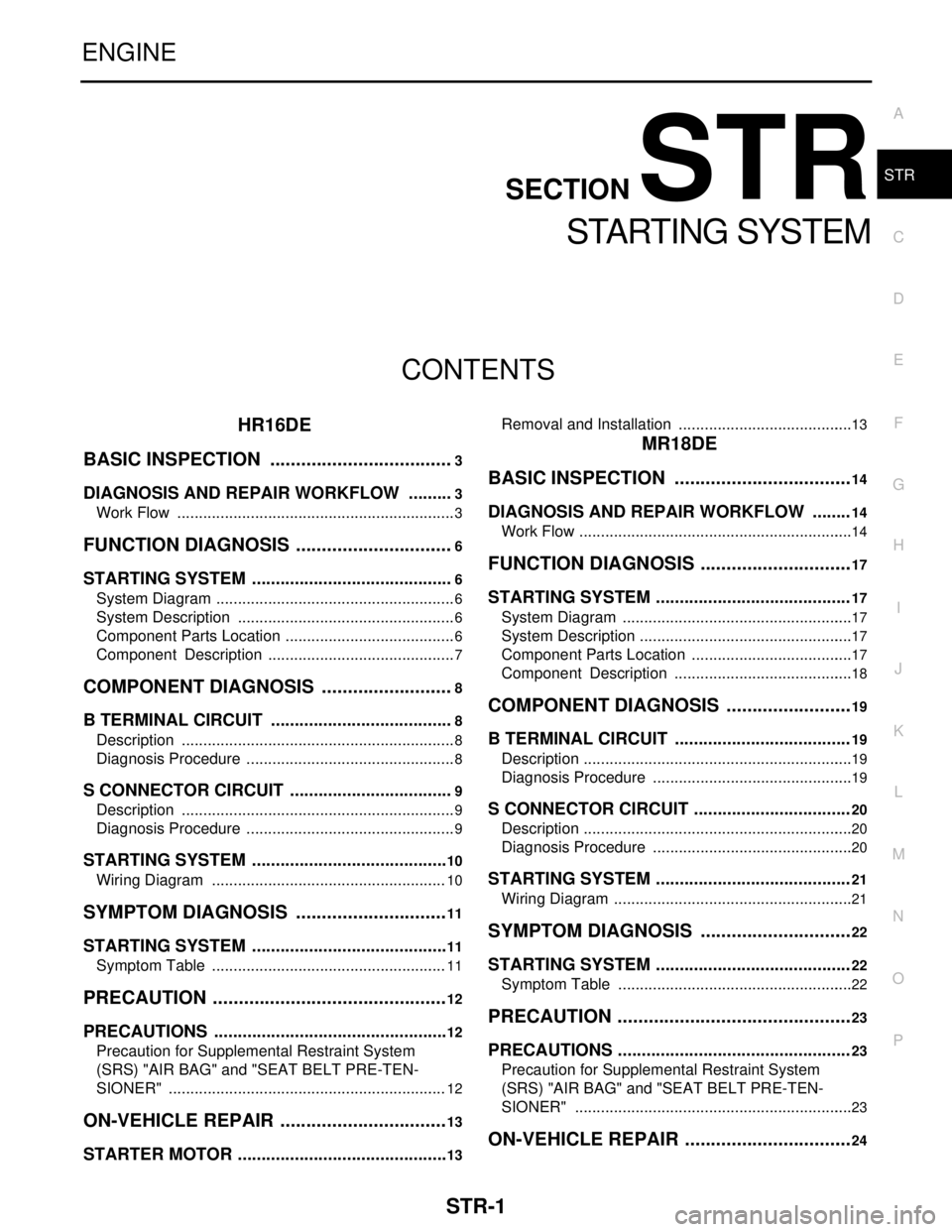
STR-1
ENGINE
C
D
E
F
G
H
I
J
K
L
M
SECTION STR
A
STR
N
O
P
CONTENTS
STARTING SYSTEM
HR16DE
BASIC INSPECTION ....................................
3
DIAGNOSIS AND REPAIR WORKFLOW ..........3
Work Flow .................................................................3
FUNCTION DIAGNOSIS ...............................6
STARTING SYSTEM ...........................................6
System Diagram ........................................................6
System Description ...................................................6
Component Parts Location ........................................6
Component Description ............................................7
COMPONENT DIAGNOSIS ..........................8
B TERMINAL CIRCUIT .......................................8
Description ................................................................8
Diagnosis Procedure .................................................8
S CONNECTOR CIRCUIT ...................................9
Description ................................................................9
Diagnosis Procedure .................................................9
STARTING SYSTEM ..........................................10
Wiring Diagram .......................................................10
SYMPTOM DIAGNOSIS ..............................11
STARTING SYSTEM ..........................................11
Symptom Table .......................................................11
PRECAUTION ..............................................12
PRECAUTIONS ..................................................12
Precaution for Supplemental Restraint System
(SRS) "AIR BAG" and "SEAT BELT PRE-TEN-
SIONER" .................................................................
12
ON-VEHICLE REPAIR .................................13
STARTER MOTOR .............................................13
Removal and Installation .........................................13
MR18DE
BASIC INSPECTION ...................................
14
DIAGNOSIS AND REPAIR WORKFLOW ........14
Work Flow ................................................................14
FUNCTION DIAGNOSIS ..............................17
STARTING SYSTEM .........................................17
System Diagram ......................................................17
System Description ..................................................17
Component Parts Location ......................................17
Component Description ..........................................18
COMPONENT DIAGNOSIS .........................19
B TERMINAL CIRCUIT .....................................19
Description ...............................................................19
Diagnosis Procedure ...............................................19
S CONNECTOR CIRCUIT .................................20
Description ...............................................................20
Diagnosis Procedure ...............................................20
STARTING SYSTEM .........................................21
Wiring Diagram ........................................................21
SYMPTOM DIAGNOSIS ..............................22
STARTING SYSTEM .........................................22
Symptom Table .......................................................22
PRECAUTION ..............................................23
PRECAUTIONS .................................................23
Precaution for Supplemental Restraint System
(SRS) "AIR BAG" and "SEAT BELT PRE-TEN-
SIONER" .................................................................
23
ON-VEHICLE REPAIR .................................24