Page 476 of 5883
CSC (CONCENTRIC SLAVE CYLINDER)
CL-11
< SERVICE INFORMATION >
C
E
F
G
H
I
J
K
L
MA
B
CL
N
O
P
CSC (CONCENTRIC SLAVE CYLINDER)
Removal and InstallationINFOID:0000000001375297
CAUTION:
If transaxle assembly is removed from the vehicle, always replace CSC (Concentric slave cylinder).
Return CSC insert to original position to remove transaxle assembly. Dust on clutch disc sliding
parts may damage CSC seal and may cause clutch fluid leakage.
Keep painted surface of the body and other parts free of clutch fluid. If it spills, wipe up immediately
and wash the affected area with water.
REMOVAL
1. Remove transaxle assembly. Refer to TM-633, "Removal and Installation" (5MT) or TM-681, "Removal
and Installation" (6MT).
2. Remove CSC bolts and the CSC from clutch housing.
INSTALLATION
Installation is in the reverse order of removal.
CAUTION:
After installation, bleed the air from the clutch hydraulic system. Refer to CL-8, "
Air Bleeding Proce-
dure".
PCIB1498E
Page 477 of 5883

CL-12
< SERVICE INFORMATION >
CLUTCH PIPING
CLUTCH PIPING
Removal and InstallationINFOID:0000000001375298
Carefully observe the following steps during clutch tube removal and installation.
CAUTION:
Do not spill clutch fluid onto painted surfaces. If it spills, wipe up immediately and wash the affected
area with water.
REMOVAL
1. Remove the battery, battery tray and brackets. Refer to PG-6, "Removal and Installation".
2. Remove the air cleaner and air duct. Refer to EM-154, "
Removal and Installation" (MR18DE) or EM-269,
"Removal and Installation" (K9K).
3. Use one of the following methods to remove hose from clutch master cylinder.
Drain clutch fluid from reservoir tank and remove hose.
Remove hose from clutch master cylinder. Immediately plug hose and reservoir tank to prevent clutch
fluid from dripping.
CAUTION:
Do not spill clutch fluid onto painted surfaces. If it spills, wipe up immediately and wash the
affected area with water.
4. Remove clutch tube lock pin from clutch master cylinder.
5. Remove clutch tube lock pin at clutch housing.
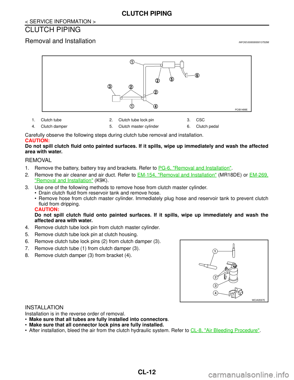
6. Remove clutch tube lock pins (2) from clutch damper (3).
7. Remove clutch tube (1) from clutch damper (3).
8. Remove clutch damper (3) from bracket (4).
INSTALLATION
Installation is in the reverse order of removal.
Make sure that all tubes are fully installed into connectors.
Make sure that all connector lock pins are fully installed.
After installation, bleed the air from the clutch hydraulic system. Refer to CL-8, "
Air Bleeding Procedure".
1. Clutch tube 2. Clutch tube lock pin 3. CSC
4. Clutch damper 5. Clutch master cylinder 6. Clutch pedal
PCIB1499E
WCIA0597E
Page 4295 of 5883
CHASSIS AND BODY MAINTENANCE
MA-55
< ON-VEHICLE MAINTENANCE >
C
D
E
F
G
H
I
J
K
L
MB
MAN
OA
2. Depress the brake pedal, loosen the bleed valve, and gradually
remove the brake fluid.
3. Clean inside of reservoir tank, and refill with new brake fluid.
4. Loosen bleed valve, depress brake pedal slowly to full stroke
and then release it. Repeat the procedure every 2 or 3 seconds
until the new brake fluid comes out, then close the bleed valve
while depressing the brake pedal. Repeat the same procedure
for each wheel.
5. Bleed air. Refer to BR-8, "
Bleeding Brake System" .
Checking Disc BrakeINFOID:0000000001730908
ROTOR
Check the rotor condition and thickness. Resurface or replace the
rotor as necessary.
CALIPER
Check the caliper for leakage.
PA D
WFIA0512E
WFIA0513E
SMA260A
SMA922A
Page 4583 of 5883

REAR SUSPENSION BEAM
RSU-11
< ON-VEHICLE REPAIR >
C
D
F
G
H
I
J
K
L
MA
B
RSU
N
O
P
REAR SUSPENSION BEAM
Removal and InstallationINFOID:0000000001724580
REMOVAL
1. Remove rear tires from vehicle using power tool.
2. Separate parking brake rear cable from rear drum brake and rear suspension beam. Refer to PB-4, "
On-
Vehicle Service" .
3. Remove wheel sensor and wheel sensor harness from wheel hub and bearing assembly and rear suspen-
sion beam. Refer to BRC-83, "
Removal and Installation" .
4. Remove lock plate and separate brake tube from brake hose.
Refer to BR-15, "
Rear Brake Tube and Hose" .
5. Remove wheel hub and bearing assembly and back plate. Refer
to RAX-6, "
Removal and Installation" .
6. Set jack under rear suspension beam.
7. Remove coil spring (left/right). Refer to RSU-10, "
Removal and
Installation" .
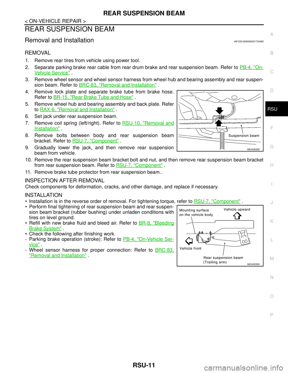
8. Remove bolts between body and rear suspension beam
bracket. Refer to RSU-7, "
Component" .
9. Gradually lower the jack, and then remove rear suspension
beam from vehicle.
10. Remove the rear suspension beam bracket bolt and nut, and then remove rear suspension beam bracket
from rear suspension beam. Refer to RSU-7, "
Component" .
11. Remove brake tube protector from rear suspension beam..
INSPECTION AFTER REMOVAL
Check components for deformation, cracks, and other damage, and replace if necessary.
INSTALLATION
Installation is in the reverse order of removal. For tightening torque, refer to RSU-7, "Component" .
Perform final tightening of rear suspension beam and rear suspen-
sion beam bracket (rubber bushing) under unladen conditions with
tires on level ground.
Refill with new brake fluid and bleed air. Refer to BR-8, "
Bleeding
Brake System" .
Check the following after finishing work.
- Parking brake operation (stroke): Refer to PB-4, "
On-Vehicle Ser-
vice" .
- Wheel sensor harness for proper connection: Refer to BRC-83,
"Removal and Installation" .
MEIA0029E
MEIA0030E
Page 5580 of 5883
![NISSAN TIIDA 2007 Service Repair Manual TM-634
< REMOVAL AND INSTALLATION >[5MT: RS5F91R]
TRANSAXLE ASSEMBLY
8. Remove engine undercover.
9. Remove front drive shafts. Refer to FAX-10, "
Removal and Installation (Left Side)" and FAX-11, "Re NISSAN TIIDA 2007 Service Repair Manual TM-634
< REMOVAL AND INSTALLATION >[5MT: RS5F91R]
TRANSAXLE ASSEMBLY
8. Remove engine undercover.
9. Remove front drive shafts. Refer to FAX-10, "
Removal and Installation (Left Side)" and FAX-11, "Re](/manual-img/5/57395/w960_57395-5579.png)
TM-634
< REMOVAL AND INSTALLATION >[5MT: RS5F91R]
TRANSAXLE ASSEMBLY
8. Remove engine undercover.
9. Remove front drive shafts. Refer to FAX-10, "
Removal and Installation (Left Side)" and FAX-11, "Removal
and Installation (Right Side)".
NOTE:
Insert a suitable plug into side oil seal after removing front drive shaft.
10. Remove heat insulator and exhaust front tube. Refer to EX-5, "
Removal and Installation".
11. Disconnect position switch harness connector and then disconnect clip from rear housing.
12. Drain gear oil. Refer to TM-628, "
Draining".
13. Disconnect select cable and shift cable from transaxle assembly. Refer to TM-630, "
Removal and Installa-
tion".
14. Support engine assembly and transaxle assembly with a jack.
CAUTION:
When setting a jack, be careful not to bring it into contact with switch.
15. Remove engine mount through bolt-securing nut. Refer to EM-89, "
Exploded View".
16. Remove LH engine mount bracket (transaxle side) bolts.
17. Remove rear engine mount bracket and rear torque rod.
18. Remove transaxle assembly to engine assembly bolts.
19. Remove transaxle assembly from the vehicle.
CAUTION:
Secure transaxle assembly to a jack while removing it.
INSTALLATION
Installation is in the reverse order of removal.
CAUTION:
When installing transaxle assembly, be careful not to bring transaxle input shaft into contact with
clutch cover.
If transaxle is removed from the vehicle, always replace CSC. Refer to CL-11, "
Removal and Installation".
When installing the transaxle assembly to the engine, install the
bolts following the standard below.
(A): M/T to engine
(B): Engine to M/T
Bleed the air from the clutch hydraulic system. Refer to CL-8, "
Air Bleeding Procedure".
After installation, check oil level, and check for leaks and loose mechanisms. Refer to TM-628, "
Inspection".
SCIA7084E
Bolt No. 1234
Quantity 2213
Bolt length “ ”
mm (in)55
(2.17)49
(1.93)69
(2.72)55
(2.17)
Tightening torque
N·m (kg-m, ft-lb)48.0
(4.9, 35)
PCIB1517E
Page 5628 of 5883
TM-682
< REMOVAL AND INSTALLATION >[6MT: RS6F94R]
TRANSAXLE ASSEMBLY
K9K
Tighten bolts to the specified torque.
Refer to CL-11, "
Removal and Installation" for CSC (Concentric Slave Cylinder) installation procedure.
Refer to TM-674, "
Removal and Installation" for select cable and shift cable installation procedure.
Bleed the air from the clutch hydraulic system. Refer to CL-8, "
Air Bleeding Procedure".
After installation, check for oil leakage and oil level. Refer to TM-672, "
Inspection".
“ ” mm (in)60 (2.36) 50 (1.97)
Tightening torque
N·m (kg-m, ft-lb)62.0 (6.3, 46) Bolt symbol A B
: Transaxle to engine
: Engine to transaxle
Bolt symbol A B C
Quantity 2 2 4
“ ” mm (in)50 (1.97) 80 (3.15) 65 (2.56)
Tightening torque
N·m (kg-m, ft-lb)48 (4.9, 35)
JPDIC0054ZZ
Page:
< prev 1-8 9-16 17-24