2007 NISSAN TIIDA sensor
[x] Cancel search: sensorPage 3167 of 5883
FUEL LEVEL SENSOR UNIT, FUEL FILTER AND FUEL PUMP ASSEMBLY
FL-7
< ON-VEHICLE REPAIR >
C
D
E
F
G
H
I
J
K
L
MA
FL
N
P O
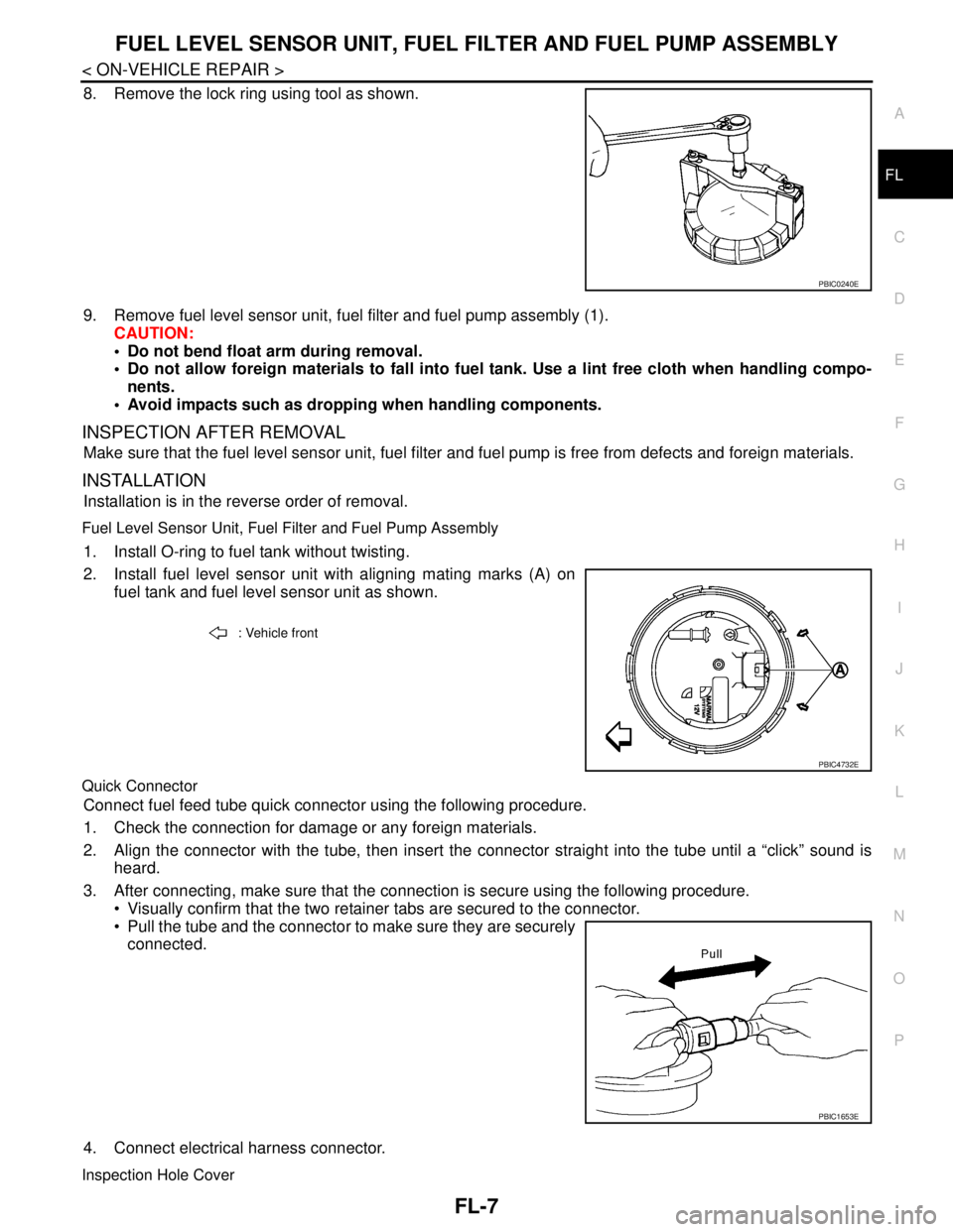
8. Remove the lock ring using tool as shown.
9. Remove fuel level sensor unit, fuel filter and fuel pump assembly (1).
CAUTION:
Do not bend float arm during removal.
Do not allow foreign materials to fall into fuel tank. Use a lint free cloth when handling compo-
nents.
Avoid impacts such as dropping when handling components.
INSPECTION AFTER REMOVAL
Make sure that the fuel level sensor unit, fuel filter and fuel pump is free from defects and foreign materials.
INSTALLATION
Installation is in the reverse order of removal.
Fuel Level Sensor Unit, Fuel Filter and Fuel Pump Assembly
1. Install O-ring to fuel tank without twisting.
2. Install fuel level sensor unit with aligning mating marks (A) on
fuel tank and fuel level sensor unit as shown.
Quick Connector
Connect fuel feed tube quick connector using the following procedure.
1. Check the connection for damage or any foreign materials.
2. Align the connector with the tube, then insert the connector straight into the tube until a “click” sound is
heard.
3. After connecting, make sure that the connection is secure using the following procedure.
Visually confirm that the two retainer tabs are secured to the connector.
Pull the tube and the connector to make sure they are securely
connected.
4. Connect electrical harness connector.
Inspection Hole Cover
PBIC0240E
: Vehicle front
PBIC4732E
PBIC1653E
Page 3168 of 5883
FL-8
< ON-VEHICLE REPAIR >
FUEL LEVEL SENSOR UNIT, FUEL FILTER AND FUEL PUMP ASSEMBLY
Before installing inspection hole cover, confirm that there are no fuel leaks. Refer to "INSPECTION AFTER
INSTALLATION".
1. Install inspection hole cover with the front mark (arrow) facing front of vehicle.
2. Lock clips by turning counterclockwise.
K9KINFOID:0000000001723040
Exploded ViewINFOID:0000000001723041
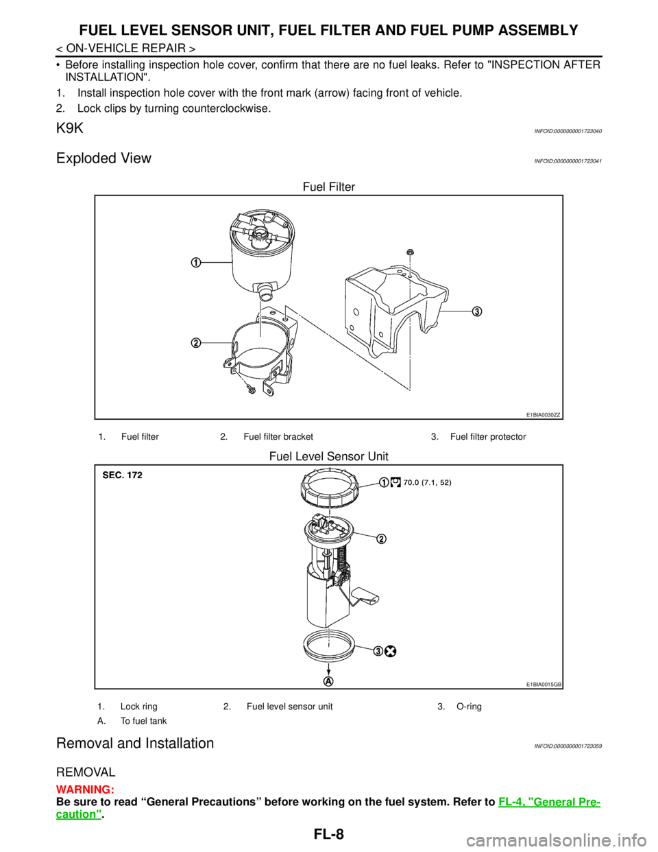
Fuel Filter
Fuel Level Sensor Unit
Removal and InstallationINFOID:0000000001723059
REMOVAL
WARNING:
Be sure to read “General Precautions” before working on the fuel system. Refer to FL-4, "
General Pre-
caution".
E1BIA0030ZZ
1. Fuel filter 2. Fuel filter bracket 3. Fuel filter protector
E1BIA0015GB
1. Lock ring 2. Fuel level sensor unit 3. O-ring
A. To fuel tank
Page 3169 of 5883
FUEL LEVEL SENSOR UNIT, FUEL FILTER AND FUEL PUMP ASSEMBLY
FL-9
< ON-VEHICLE REPAIR >
C
D
E
F
G
H
I
J
K
L
MA
FL
N
P O
1. Disconnect battery ground cable.
2. Open fuel filler lid and filler cap to release the pressure inside the fuel tank.
3. Remove rear seat cushion. Refer to SE-18, "
Removal and Installation".
4. Remove the fuel pump inspection hole cover.
5. Disconnect electrical connector.
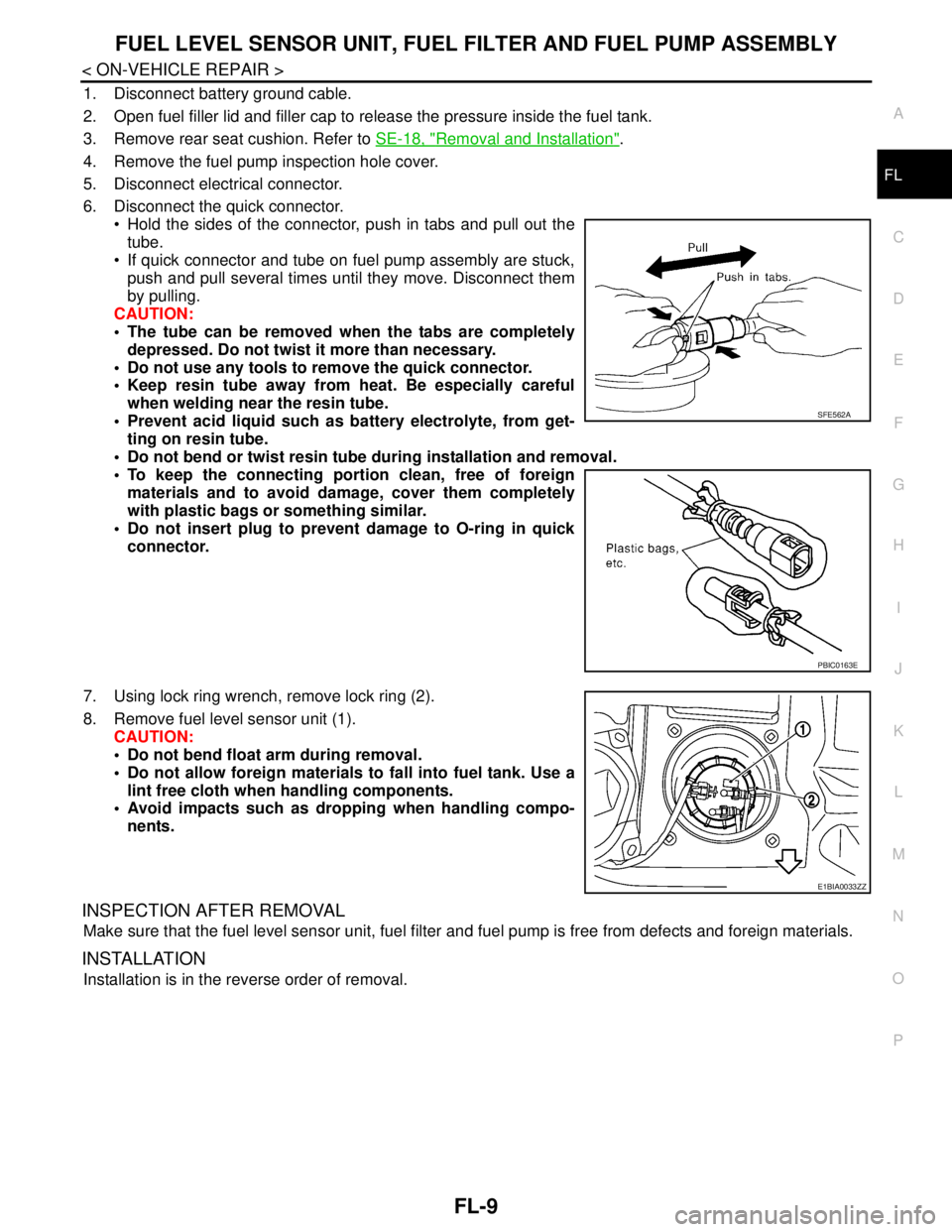
6. Disconnect the quick connector.
Hold the sides of the connector, push in tabs and pull out the
tube.
If quick connector and tube on fuel pump assembly are stuck,
push and pull several times until they move. Disconnect them
by pulling.
CAUTION:
The tube can be removed when the tabs are completely
depressed. Do not twist it more than necessary.
Do not use any tools to remove the quick connector.
Keep resin tube away from heat. Be especially careful
when welding near the resin tube.
Prevent acid liquid such as battery electrolyte, from get-
ting on resin tube.
Do not bend or twist resin tube during installation and removal.
To keep the connecting portion clean, free of foreign
materials and to avoid damage, cover them completely
with plastic bags or something similar.
Do not insert plug to prevent damage to O-ring in quick
connector.
7. Using lock ring wrench, remove lock ring (2).
8. Remove fuel level sensor unit (1).
CAUTION:
Do not bend float arm during removal.
Do not allow foreign materials to fall into fuel tank. Use a
lint free cloth when handling components.
Avoid impacts such as dropping when handling compo-
nents.
INSPECTION AFTER REMOVAL
Make sure that the fuel level sensor unit, fuel filter and fuel pump is free from defects and foreign materials.
INSTALLATION
Installation is in the reverse order of removal.
SFE562A
PBIC0163E
E1BIA0033ZZ
Page 3173 of 5883
FUEL TANK
FL-13
< ON-VEHICLE REPAIR >
C
D
E
F
G
H
I
J
K
L
MA
FL
N
P O
K9KINFOID:0000000001723031
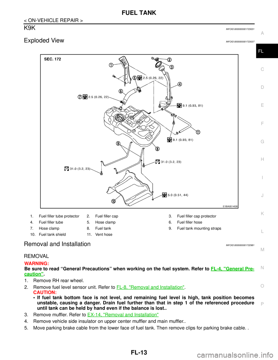
Exploded ViewINFOID:0000000001723037
Removal and InstallationINFOID:0000000001722981
REMOVAL
WARNING:
Be sure to read “General Precautions” when working on the fuel system. Refer to FL-4, "
General Pre-
caution".
1. Remove RH rear wheel.
2. Remove fuel level sensor unit. Refer to FL-8, "
Removal and Installation".
CAUTION:
If fuel tank bottom face is not level, and remaining fuel level is high, tank position becomes
unstable, causing a danger. Drain fuel further than that in step 1 of the referenced procedure
until tank can be held by hand even if the balance is lost..
3. Remove muffler. Refer to EX-14, "
Removal and Installation"
4. Remove vehicle side insulator on upper center muffler and main muffler..
5. Move parking brake cable from the lower face of fuel tank. Then remove clips for parking brake cable. .
1. Fuel filler tube protector 2. Fuel filler cap 3. Fuel filler cap protector
4. Fuel filler tube 5. Hose clamp 6. Fuel filler hose
7. Hose clamp 8. Fuel tank 9. Fuel tank mounting straps
10. Fuel tank shield 11. Vent hose
E1BIA0014GB
Page 3183 of 5883
FRONT SUSPENSION ASSEMBLY
FSU-7
< ON-VEHICLE MAINTENANCE >
C
D
F
G
H
I
J
K
L
MA
B
FSU
N
O
P
The alignment specifications programmed into your alignment machine that operate these indicators
may not be correct.
This may result in an ERROR.
2. Some newer alignment machines are equipped with an optional “Rolling Compensation” method to “com-
pensate” the sensors (alignment targets or head units). Do NOT use this “Rolling Compensation”
method.
Use the “Jacking Compensation” method. After installing the alignment targets or head units, raise the
vehicle and rotate the wheels 1/2 turn both ways.
See Instructions in the alignment machine you are using for more information.
CAMBER, CASTER AND KINGPIN INCLINATION ANGLES INSPECTION
Camber, caster, kingpin inclination angles cannot be adjusted.
Before inspection, mount front wheels onto turning radius gauge. Mount rear wheels onto a stand that has
same height so vehicle will remain horizontal.
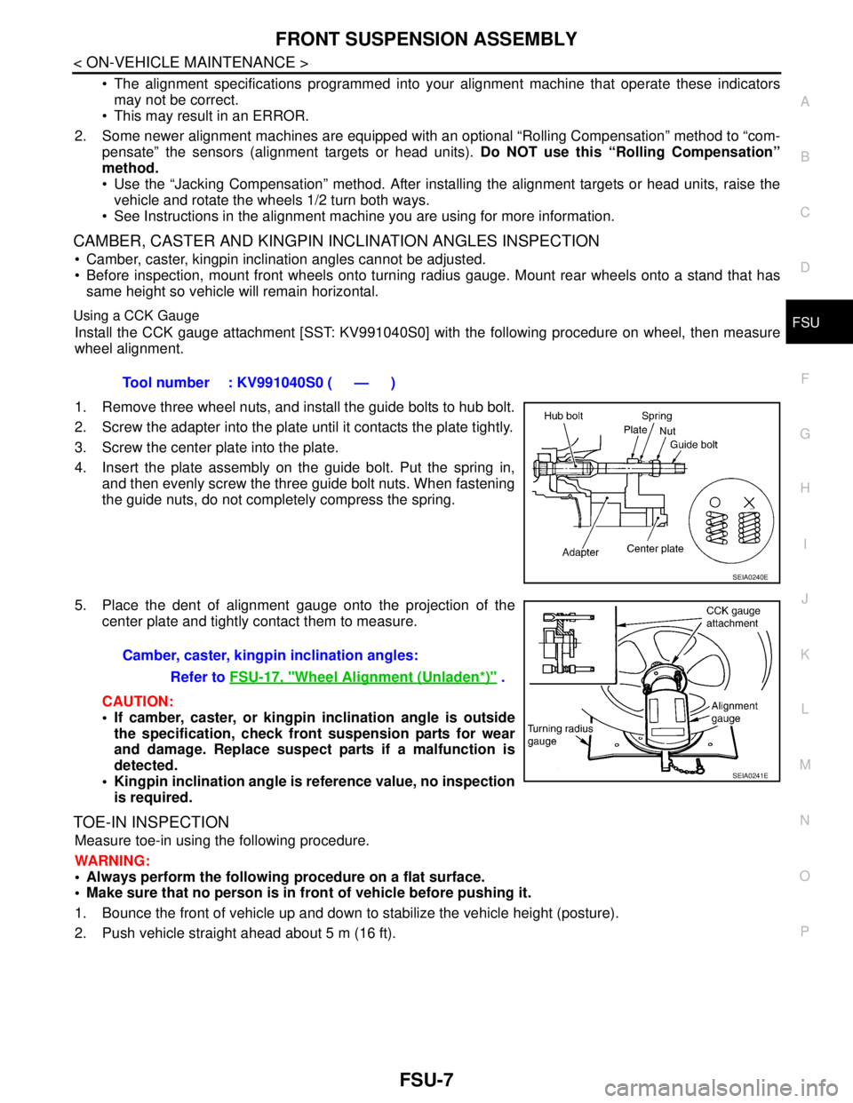
Using a CCK Gauge
Install the CCK gauge attachment [SST: KV991040S0] with the following procedure on wheel, then measure
wheel alignment.
1. Remove three wheel nuts, and install the guide bolts to hub bolt.
2. Screw the adapter into the plate until it contacts the plate tightly.
3. Screw the center plate into the plate.
4. Insert the plate assembly on the guide bolt. Put the spring in,
and then evenly screw the three guide bolt nuts. When fastening
the guide nuts, do not completely compress the spring.
5. Place the dent of alignment gauge onto the projection of the
center plate and tightly contact them to measure.
CAUTION:
If camber, caster, or kingpin inclination angle is outside
the specification, check front suspension parts for wear
and damage. Replace suspect parts if a malfunction is
detected.
Kingpin inclination angle is reference value, no inspection
is required.
TOE-IN INSPECTION
Measure toe-in using the following procedure.
WARNING:
Always perform the following procedure on a flat surface.
Make sure that no person is in front of vehicle before pushing it.
1. Bounce the front of vehicle up and down to stabilize the vehicle height (posture).
2. Push vehicle straight ahead about 5 m (16 ft).Tool number : KV991040S0 ( — )
SEIA0240E
Camber, caster, kingpin inclination angles:
Refer to FSU-17, "
Wheel Alignment (Unladen*)" .
SEIA0241E
Page 3187 of 5883
FRONT SUSPENSION ASSEMBLY
FSU-11
< REMOVAL AND INSTALLATION >
C
D
F
G
H
I
J
K
L
MA
B
FSU
N
O
P
REMOVAL AND INSTALLATION
FRONT SUSPENSION ASSEMBLY
Removal and InstallationINFOID:0000000001716901
REMOVAL
1. Separate intermediate shaft from steering gear pinion shaft. Refer to ST-9, "Removal and Installation".
2. Remove front tires from vehicle using a power tool.
3. Remove wheel sensor from steering knuckle. Refer to BRC-182, "
Removal and Installation".
CAUTION:
Do not pull on wheel sensor harness.
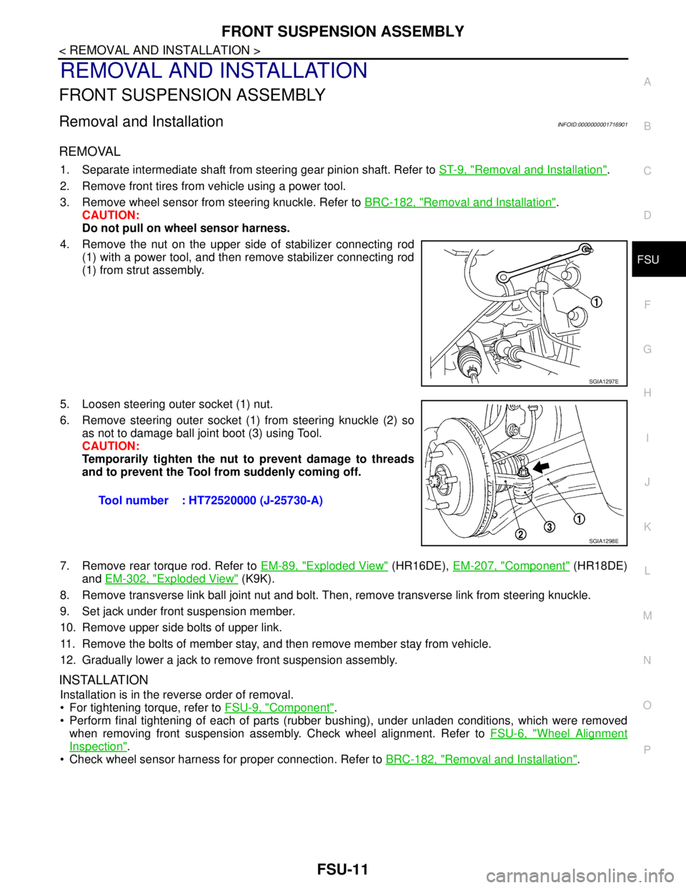
4. Remove the nut on the upper side of stabilizer connecting rod
(1) with a power tool, and then remove stabilizer connecting rod
(1) from strut assembly.
5. Loosen steering outer socket (1) nut.
6. Remove steering outer socket (1) from steering knuckle (2) so
as not to damage ball joint boot (3) using Tool.
CAUTION:
Temporarily tighten the nut to prevent damage to threads
and to prevent the Tool from suddenly coming off.
7. Remove rear torque rod. Refer to EM-89, "
Exploded View" (HR16DE), EM-207, "Component" (HR18DE)
and EM-302, "
Exploded View" (K9K).
8. Remove transverse link ball joint nut and bolt. Then, remove transverse link from steering knuckle.
9. Set jack under front suspension member.
10. Remove upper side bolts of upper link.
11. Remove the bolts of member stay, and then remove member stay from vehicle.
12. Gradually lower a jack to remove front suspension assembly.
INSTALLATION
Installation is in the reverse order of removal.
For tightening torque, refer to FSU-9, "
Component".
Perform final tightening of each of parts (rubber bushing), under unladen conditions, which were removed
when removing front suspension assembly. Check wheel alignment. Refer to FSU-6, "
Wheel Alignment
Inspection".
Check wheel sensor harness for proper connection. Refer to BRC-182, "
Removal and Installation".
SGIA1297E
Tool number : HT72520000 (J-25730-A)
SGIA1298E
Page 3188 of 5883
FSU-12
< REMOVAL AND INSTALLATION >
COIL SPRING AND STRUT
COIL SPRING AND STRUT
Removal and InstallationINFOID:0000000001716888
REMOVAL
1. Remove cowl top panel. Refer to EXT-20, "Removal and Installation" .
2. Remove front tires using power tool.
3. Remove harness of wheel sensor from strut assembly. Refer to BRC-182, "
Removal and Installation" .
CAUTION:
Do not pull on wheel sensor harness.
4. Remove brake hose lock plate. Refer to BR-14, "
Front Brake Tube and Hose" .
5. Remove the nut on the upper side of stabilizer connecting rod using power tool, and then remove stabi-
lizer connecting rod from strut assembly.
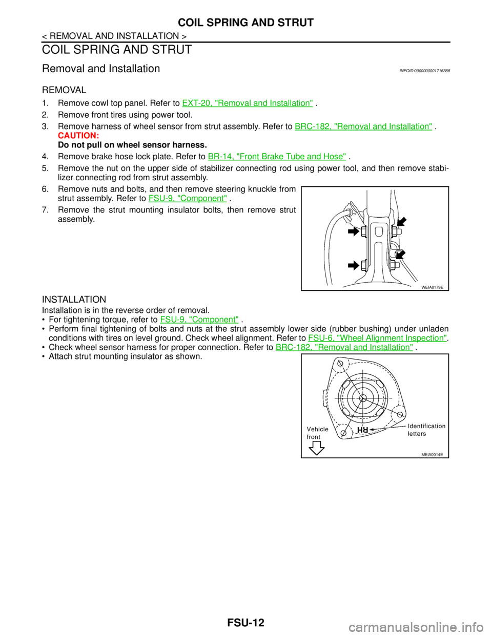
6. Remove nuts and bolts, and then remove steering knuckle from
strut assembly. Refer to FSU-9, "
Component" .
7. Remove the strut mounting insulator bolts, then remove strut
assembly.
INSTALLATION
Installation is in the reverse order of removal.
For tightening torque, refer to FSU-9, "
Component" .
Perform final tightening of bolts and nuts at the strut assembly lower side (rubber bushing) under unladen
conditions with tires on level ground. Check wheel alignment. Refer to FSU-6, "
Wheel Alignment Inspection".
Check wheel sensor harness for proper connection. Refer to BRC-182, "
Removal and Installation" .
Attach strut mounting insulator as shown.
WEIA0179E
MEIA0014E
Page 3199 of 5883
HOW TO USE THIS MANUAL
GI-5
< HOW TO USE THIS MANUAL >
C
D
E
F
G
H
I
J
K
L
MB
GI
N
O
P
SYMBOLS
How to Follow Trouble DiagnosisINFOID:0000000001606148
DESCRIPTION
NOTICE:
Trouble diagnoses indicate work procedures required to diagnose problems effectively. Observe the following
instructions before diagnosing.
1.Before performing trouble diagnoses, read the “Preliminary Check”, the “Symptom Chart” or the
“Work Flow”.
2.After repairs, re-check that the problem has been completely eliminated.
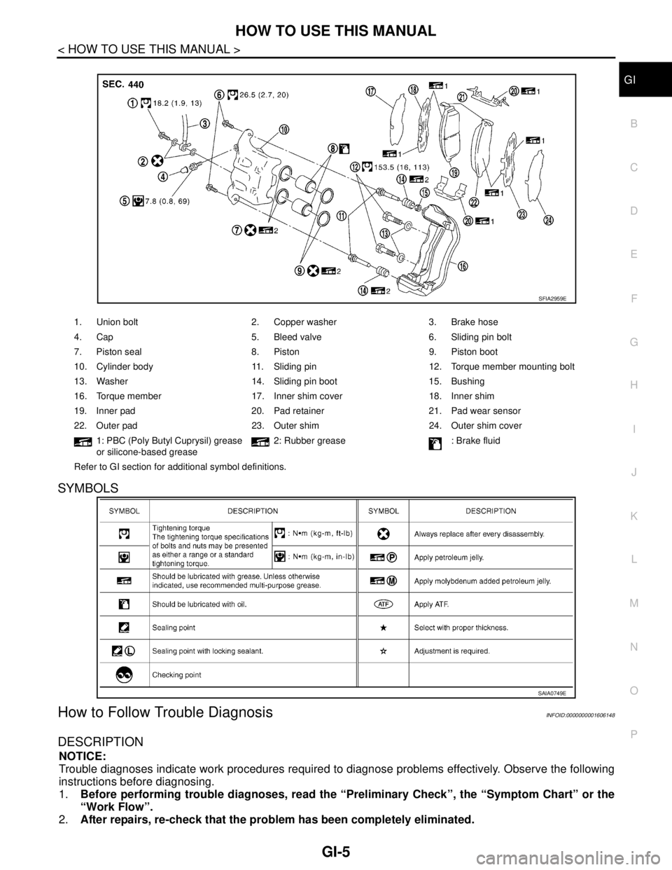
1. Union bolt 2. Copper washer 3. Brake hose
4. Cap 5. Bleed valve 6. Sliding pin bolt
7. Piston seal 8. Piston 9. Piston boot
10. Cylinder body 11. Sliding pin 12. Torque member mounting bolt
13. Washer 14. Sliding pin boot 15. Bushing
16. Torque member 17. Inner shim cover 18. Inner shim
19. Inner pad 20. Pad retainer 21. Pad wear sensor
22. Outer pad 23. Outer shim 24. Outer shim cover
1: PBC (Poly Butyl Cuprysil) grease
or silicone-based grease2: Rubber grease : Brake fluid
Refer to GI section for additional symbol definitions.
SFIA2959E
SAIA0749E