2007 NISSAN TIIDA sensor
[x] Cancel search: sensorPage 3092 of 5883
AUTO LIGHT SYSTEM
EXL-91
< ON-VEHICLE REPAIR >
C
D
E
F
G
H
I
J
K
MA
B
EXL
N
O
P
AUTO LIGHT SYSTEM
Removal and Installation of Light and Rain SensorINFOID:0000000001530408
REMOVAL
1. Remove the rear view mirror. Refer to MIR-9, "Removal and Installation".
2. Disconnect the light and rain sensor connector.
3. Remove the light and rain sensor.
INSTALLATION
Installation is in the reverse order of removal.
Page 3141 of 5883

FRONT WHEEL HUB AND KNUCKLE
FAX-7
< REMOVAL AND INSTALLATION >
C
E
F
G
H
I
J
K
L
MA
B
FA X
N
O
P
REMOVAL AND INSTALLATION
FRONT WHEEL HUB AND KNUCKLE
Removal and InstallationINFOID:0000000001716789
COMPONENT
REMOVAL
1. Remove wheel and tire using power tool. Refer to WT-6, "Rotation" .
2. Without disassembling the hydraulic lines, remove the torque member bolts using power tool. Then repo-
sition the torque member and brake caliper assembly aside with wire. Refer to BR-25, "
Removal and
Installation of Brake Caliper Assembly" .
CAUTION:
Do not depress brake pedal while brake caliper is removed.
3. Put alignment marks on disc rotor and wheel hub and bearing
assembly, then remove disc rotor.
4. Remove wheel sensor from steering knuckle. Refer to BRC-182, "
Removal and Installation" .
CAUTION:
Do not pull on wheel sensor harness.
1. Drive shaft 2. Steering knuckle 3. Splash guard
4. Wheel hub and bearing assembly 5. Cotter pin
WDIA0366E
SDIA1480E
Page 3144 of 5883
FAX-10
< REMOVAL AND INSTALLATION >
FRONT DRIVE SHAFT
FRONT DRIVE SHAFT
Removal and Installation (Left Side)INFOID:0000000001716796
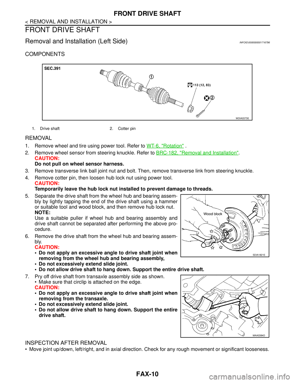
COMPONENTS
REMOVAL
1. Remove wheel and tire using power tool. Refer to WT-6, "Rotation" .
2. Remove wheel sensor from steering knuckle. Refer to BRC-182, "
Removal and Installation".
CAUTION:
Do not pull on wheel sensor harness.
3. Remove transverse link ball joint nut and bolt. Then, remove transverse link from steering knuckle.
4. Remove cotter pin, then loosen hub lock nut using power tool.
CAUTION:
Temporarily leave the hub lock nut installed to prevent damage to threads.
5. Separate the drive shaft from the wheel hub and bearing assem-
bly by lightly tapping the end of the drive shaft using a hammer
or suitable tool and wood block, and then remove hub lock nut.
NOTE:
Use a suitable puller if wheel hub and bearing assembly and
drive shaft cannot be separated after performing the above pro-
cedure.
6. Remove the drive shaft from the wheel hub and bearing assem-
bly.
CAUTION:
Do not apply an excessive angle to drive shaft joint when
removing from the wheel hub and bearing assembly,
Do not excessively extend slide joint.
Do not allow drive shaft to hang down. Support the entire drive shaft.
7. Pry off drive shaft from transaxle assembly side as shown.
Make sure that circlip is attached on the edge.
CAUTION:
Do not apply an excessive angle to drive shaft joint when
removing from the transaxle.
Do not excessively extend slide joint.
Do not allow drive shaft to hang down. Support the entire
drive shaft.
INSPECTION AFTER REMOVAL
Move joint up/down, left/right, and in axial direction. Check for any rough movement or significant looseness.
1. Drive shaft 2. Cotter pin
WDIA0373E
SDIA1821E
MAA0384D
Page 3145 of 5883
FRONT DRIVE SHAFT
FAX-11
< REMOVAL AND INSTALLATION >
C
E
F
G
H
I
J
K
L
MA
B
FA X
N
O
P
Check boot for cracks or other damage, and for grease leakage.
If damaged, disassemble drive shaft to verify damage, and repair
or replace as necessary.
INSTALLATION
Installation is in the reverse order of removal.
CAUTION:
Do not reuse non-reusable parts.
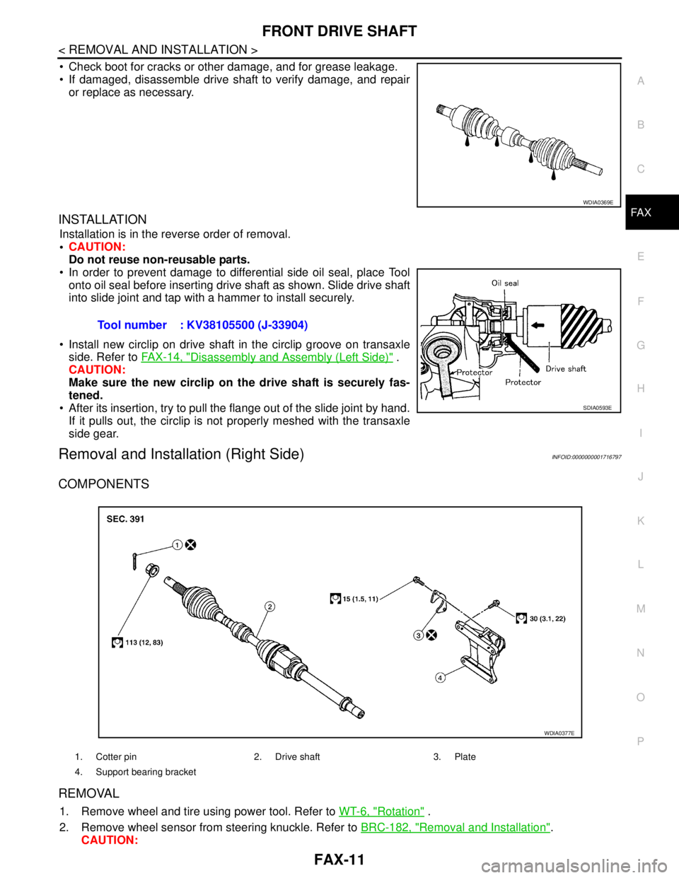
In order to prevent damage to differential side oil seal, place Tool
onto oil seal before inserting drive shaft as shown. Slide drive shaft
into slide joint and tap with a hammer to install securely.
Install new circlip on drive shaft in the circlip groove on transaxle
side. Refer to FAX-14, "
Disassembly and Assembly (Left Side)" .
CAUTION:
Make sure the new circlip on the drive shaft is securely fas-
tened.
After its insertion, try to pull the flange out of the slide joint by hand.
If it pulls out, the circlip is not properly meshed with the transaxle
side gear.
Removal and Installation (Right Side)INFOID:0000000001716797
COMPONENTS
REMOVAL
1. Remove wheel and tire using power tool. Refer to WT-6, "Rotation" .
2. Remove wheel sensor from steering knuckle. Refer to BRC-182, "
Removal and Installation".
CAUTION:
WDIA0369E
Tool number : KV38105500 (J-33904)
SDIA0593E
1. Cotter pin 2. Drive shaft 3. Plate
4. Support bearing bracket
WDIA0377E
Page 3146 of 5883
FAX-12
< REMOVAL AND INSTALLATION >
FRONT DRIVE SHAFT
Do not pull on wheel sensor harness.
3. Remove transverse link ball joint nut and bolt. Then, remove transverse link from steering knuckle.
4. Remove cotter pin, then loosen hub lock nut using power tool.
CAUTION:
Temporarily leave the hub lock nut installed to prevent damage to threads.
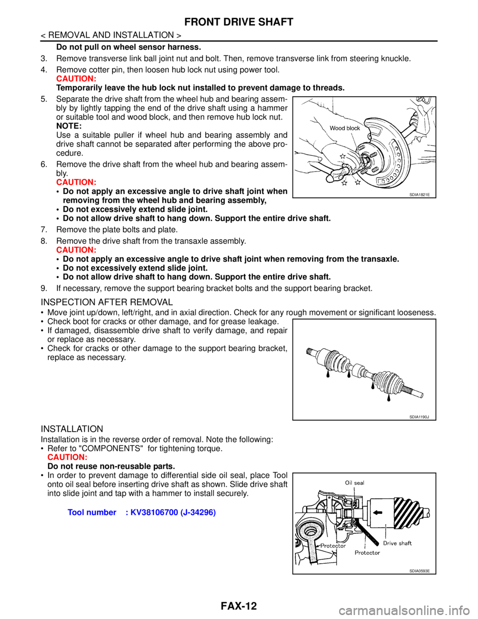
5. Separate the drive shaft from the wheel hub and bearing assem-
bly by lightly tapping the end of the drive shaft using a hammer
or suitable tool and wood block, and then remove hub lock nut.
NOTE:
Use a suitable puller if wheel hub and bearing assembly and
drive shaft cannot be separated after performing the above pro-
cedure.
6. Remove the drive shaft from the wheel hub and bearing assem-
bly.
CAUTION:
Do not apply an excessive angle to drive shaft joint when
removing from the wheel hub and bearing assembly,
Do not excessively extend slide joint.
Do not allow drive shaft to hang down. Support the entire drive shaft.
7. Remove the plate bolts and plate.
8. Remove the drive shaft from the transaxle assembly.
CAUTION:
Do not apply an excessive angle to drive shaft joint when removing from the transaxle.
Do not excessively extend slide joint.
Do not allow drive shaft to hang down. Support the entire drive shaft.
9. If necessary, remove the support bearing bracket bolts and the support bearing bracket.
INSPECTION AFTER REMOVAL
Move joint up/down, left/right, and in axial direction. Check for any rough movement or significant looseness.
Check boot for cracks or other damage, and for grease leakage.
If damaged, disassemble drive shaft to verify damage, and repair
or replace as necessary.
Check for cracks or other damage to the support bearing bracket,
replace as necessary.
INSTALLATION
Installation is in the reverse order of removal. Note the following:
Refer to "COMPONENTS" for tightening torque.
CAUTION:
Do not reuse non-reusable parts.
In order to prevent damage to differential side oil seal, place Tool
onto oil seal before inserting drive shaft as shown. Slide drive shaft
into slide joint and tap with a hammer to install securely.
SDIA1821E
SDIA1190J
Tool number : KV38106700 (J-34296)
SDIA0593E
Page 3161 of 5883
FL-1
ENGINE
C
D
E
F
G
H
I
J
K
L
M
SECTION FL
A
FL
N
O
P
CONTENTS
FUEL SYSTEM
PRECAUTION ...............................................2
PRECAUTIONS ...................................................2
Precaution for Supplemental Restraint System
(SRS) "AIR BAG" and "SEAT BELT PRE-TEN-
SIONER" ...................................................................
2
PREPARATION ............................................3
PREPARATION ...................................................3
Special Service Tool .................................................3
ON-VEHICLE MAINTENANCE .....................4
FUEL SYSTEM ....................................................4
Checking Fuel Line ...................................................4
General Precaution ...................................................4
ON-VEHICLE REPAIR ..................................5
FUEL LEVEL SENSOR UNIT, FUEL FILTER
AND FUEL PUMP ASSEMBLY ..........................
5
HR16DE, HR18DE ...................................................5
Exploded View ..........................................................5
Removal and Installation ..........................................5
K9K ...........................................................................8
Exploded View ..........................................................8
Removal and Installation ..........................................8
FUEL TANK ......................................................10
HR16DE, HR18DE ..................................................10
Exploded View .........................................................10
Removal and Installation .........................................10
K9K ..........................................................................13
Exploded View .........................................................13
Removal and Installation .........................................13
SERVICE DATA AND SPECIFICATIONS
(SDS) ............................................................
16
SERVICE DATA AND SPECIFICATIONS
(SDS) .................................................................
16
Standard and Limit ..................................................16
Page 3165 of 5883
FUEL LEVEL SENSOR UNIT, FUEL FILTER AND FUEL PUMP ASSEMBLY
FL-5
< ON-VEHICLE REPAIR >
C
D
E
F
G
H
I
J
K
L
MA
FL
N
P O
ON-VEHICLE REPAIR
FUEL LEVEL SENSOR UNIT, FUEL FILTER AND FUEL PUMP ASSEMBLY
HR16DE, HR18DEINFOID:0000000001723038
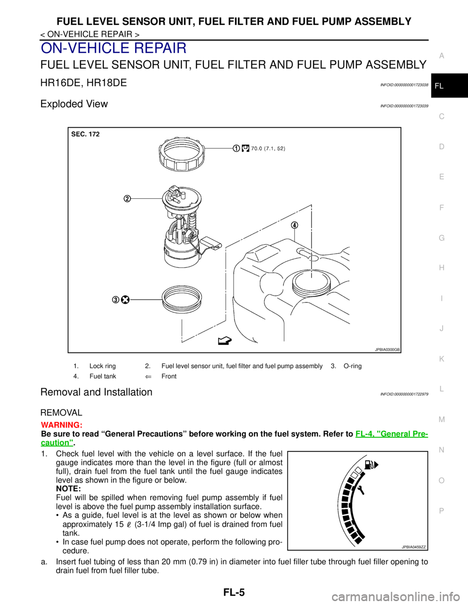
Exploded ViewINFOID:0000000001723039
Removal and InstallationINFOID:0000000001722979
REMOVAL
WARNING:
Be sure to read “General Precautions” before working on the fuel system. Refer to FL-4, "
General Pre-
caution".
1. Check fuel level with the vehicle on a level surface. If the fuel
gauge indicates more than the level in the figure (full or almost
full), drain fuel from the fuel tank until the fuel gauge indicates
level as shown in the figure or below.
NOTE:
Fuel will be spilled when removing fuel pump assembly if fuel
level is above the fuel pump assembly installation surface.
As a guide, fuel level is at the level as shown or below when
approximately 15 (3-1/4 Imp gal) of fuel is drained from fuel
tank.
In case fuel pump does not operate, perform the following pro-
cedure.
a. Insert fuel tubing of less than 20 mm (0.79 in) in diameter into fuel filler tube through fuel filler opening to
drain fuel from fuel filler tube.
1. Lock ring 2. Fuel level sensor unit, fuel filter and fuel pump assembly 3. O-ring
4. Fuel tank⇐Front
JPBIA0300GB
JPBIA0459ZZ
Page 3166 of 5883
FL-6
< ON-VEHICLE REPAIR >
FUEL LEVEL SENSOR UNIT, FUEL FILTER AND FUEL PUMP ASSEMBLY
b. Disconnect fuel filler hose from fuel filler tube. Refer to FL-10, "HR16DE, HR18DE".
c. Insert fuel tubing into fuel tank through fuel filler hose to drain fuel from fuel tank.
2. Release the fuel pressure from the fuel lines. Refer to EC-377, "
Inspection" (HR16DE with EURO-OBD),
EC-681, "
Inspection" (HR16DE without EURO-OBD), EC-1035, "Inspection" (MR18DE).
3. Open fuel filler lid.
4. Open fuel door and unscrew the fuel filler cap to release the pressure inside the fuel tank.
5. Remove rear seat bottom. Refer to SE-18, "
Removal and Installation".
6. Turn the four retainers 90° in a clockwise direction and remove the fuel pump inspection hole cover.
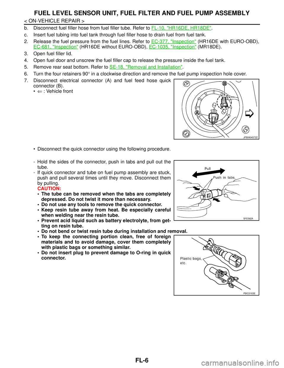
7. Disconnect electrical connector (A) and fuel feed hose quick
connector (B).
⇐ : Vehicle front
Disconnect the quick connector using the following procedure.
- Hold the sides of the connector, push in tabs and pull out the
tube.
- If quick connector and tube on fuel pump assembly are stuck,
push and pull several times until they move. Disconnect them
by pulling.
CAUTION:
The tube can be removed when the tabs are completely
depressed. Do not twist it more than necessary.
Do not use any tools to remove the quick connector.
Keep resin tube away from heat. Be especially careful
when welding near the resin tube.
Prevent acid liquid such as battery electrolyte, from get-
ting on resin tube.
Do not bend or twist resin tube during installation and removal.
To keep the connecting portion clean, free of foreign
materials and to avoid damage, cover them completely
with plastic bags or something similar.
Do not insert plug to prevent damage to O-ring in quick
connector.
JPBIA0457ZZ
SFE562A
PBIC0163E