2007 NISSAN TIIDA sensor
[x] Cancel search: sensorPage 2994 of 5883
![NISSAN TIIDA 2007 Service Repair Manual EX-8
< PREPARATION >[MR18DE]
PREPARATION
PREPARATION
PREPARATION
Special Service ToolsINFOID:0000000001696384
Commercial Service ToolsINFOID:0000000001696385
Tool number
Tool nameDescription
KV1011440 NISSAN TIIDA 2007 Service Repair Manual EX-8
< PREPARATION >[MR18DE]
PREPARATION
PREPARATION
PREPARATION
Special Service ToolsINFOID:0000000001696384
Commercial Service ToolsINFOID:0000000001696385
Tool number
Tool nameDescription
KV1011440](/manual-img/5/57395/w960_57395-2993.png)
EX-8
< PREPARATION >[MR18DE]
PREPARATION
PREPARATION
PREPARATION
Special Service ToolsINFOID:0000000001696384
Commercial Service ToolsINFOID:0000000001696385
Tool number
Tool nameDescription
KV10114400
Heated oxygen sensor wrenchLoosening or tightening heated oxygen sen-
sor 2
For 22 mm (0.87 in) width hexagon nut
S-NT636
Tool nameDescription
Heated oxygen sensor thread cleaner Reconditioning the exhaust system threads
before installing a new heated oxygen sensor
(Use with anti-seize lubricant shown below.)
a: 18 mm (0.71 in) dia. for zirconia heated
oxygen sensor
b: 12 mm (0.47 in) dia. for titania heated ox-
ygen sensor
Anti-seize lubricant (Permatex 133AR
or equivalent meeting MIL specifica-
tion MIL-A-907)Lubricating heated oxygen sensor thread
cleaner when reconditioning exhaust system
threads
AEM488
AEM489
Page 2996 of 5883
![NISSAN TIIDA 2007 Service Repair Manual EX-10
< ON-VEHICLE REPAIR >[MR18DE]
EXHAUST SYSTEM
ON-VEHICLE REPAIR
EXHAUST SYSTEM
ComponentINFOID:0000000001696508
Removal and InstallationINFOID:0000000001696507
REMOVAL
CAUTION:
Be sure to use g NISSAN TIIDA 2007 Service Repair Manual EX-10
< ON-VEHICLE REPAIR >[MR18DE]
EXHAUST SYSTEM
ON-VEHICLE REPAIR
EXHAUST SYSTEM
ComponentINFOID:0000000001696508
Removal and InstallationINFOID:0000000001696507
REMOVAL
CAUTION:
Be sure to use g](/manual-img/5/57395/w960_57395-2995.png)
EX-10
< ON-VEHICLE REPAIR >[MR18DE]
EXHAUST SYSTEM
ON-VEHICLE REPAIR
EXHAUST SYSTEM
ComponentINFOID:0000000001696508
Removal and InstallationINFOID:0000000001696507
REMOVAL
CAUTION:
Be sure to use genuine NISSAN exhaust system parts or equivalents which are specially designed
for heat resistance, corrosion resistance and shape.
Perform the operation with the exhaust system fully cooled down because the system will be hot
just after the engine stops.
Be careful not to cut your hand on heat insulator edge.
1. Disconnect harness connector of heated oxygen sensor 2.
Using Tool, remove heated oxygen sensor 2.
CAUTION:
Be careful not to damage heated oxygen sensor 2.
a.
1. Main muffler 2. Mounting rubber 3. Ring gasket
4. Center muffler 5. Mounting rubber 6. Spring
7. Seal bearing 8. Heated oxygen sensor 2 9. Exhaust front tube
10. Seal bearing 11. Stud bolt 12. Spring
13. Ground cable
WBIA0844E
Tool number : KV10114400 (J-38365)
Page 2997 of 5883
![NISSAN TIIDA 2007 Service Repair Manual EXHAUST SYSTEM
EX-11
< ON-VEHICLE REPAIR >[MR18DE]
C
D
E
F
G
H
I
J
K
L
MA
EX
N
P O
2. Disconnect each joint and mounting rubber.
INSTALLATION
Installation is in the reverse order of removal.
CAUTION: NISSAN TIIDA 2007 Service Repair Manual EXHAUST SYSTEM
EX-11
< ON-VEHICLE REPAIR >[MR18DE]
C
D
E
F
G
H
I
J
K
L
MA
EX
N
P O
2. Disconnect each joint and mounting rubber.
INSTALLATION
Installation is in the reverse order of removal.
CAUTION:](/manual-img/5/57395/w960_57395-2996.png)
EXHAUST SYSTEM
EX-11
< ON-VEHICLE REPAIR >[MR18DE]
C
D
E
F
G
H
I
J
K
L
MA
EX
N
P O
2. Disconnect each joint and mounting rubber.
INSTALLATION
Installation is in the reverse order of removal.
CAUTION:
Always replace exhaust gaskets and seal bearings with new ones when installing.
Discard any heated oxygen sensor 2 which has been dropped from a height of more than 0.5 m (19.7
in) onto a hard surface such as a concrete floor; use a new one.
Before installing a new heated oxygen sensor 2, clean exhaust system threads using the heated oxy-
gen sensor thread cleaner and apply anti-seize lubricant (commercial service tool).
Do not over tighten heated oxygen sensor 2. Doing so may cause damage to the heated oxygen sen-
sor 2, resulting in the “MIL” coming on.
Remove deposits from the sealing surface of each connection. Connect them securely to avoid
exhaust leakage.
Temporarily tighten nuts on the exhaust manifold side and bolts on the vehicle side. Check each part
for unusual interference, and then tighten them to the specified torque.
When installing each mounting rubber, avoid twisting or unusual extension in up/down and right/left
directions.
Exhaust Manifold to Exhaust Front Tube
1. Securely insert seal bearing (2) into exhaust manifold (1) side in
the direction shown.
Exhaust front tube (5)
CAUTION:
Be careful not to damage seal bearing surface when install-
ing.
2. Install spring (3), tighten nut (4).
Be careful that the stud bolt nut does not interfere with the
flanged area ( ).
Make sure the spring (3) sits properly on the flange surface by
aligning it to the locator dimples.
Exhaust Front Tube to Center Muffler
1. Securely insert seal bearing (2) into exhaust front tube (1) side
in the direction shown.
Center muffler (5)
CAUTION:
Be careful not to damage seal bearing surface when install-
ing.
2. With spring (3), tighten bolt (4).
Be careful that the stud bolt does not interfere with the flanged
area ( ).
Make sure the spring (3) sits properly on the flange surface by
aligning it to the locator dimples.
INSPECTION AFTER INSTALLATION
With the engine running, check exhaust tube joints for exhaust leakage and unusual noise.
Check to ensure that brackets and mounting rubbers are installed properly and free from undue stress.
Improper installation could result in excessive noise and vibration.
InspectionINFOID:0000000001696389
INSPECTION AFTER INSTALLATION
Make sure clearance between tail tube and rear bumper is even.
With engine running, check exhaust tube joints for gas leakage and unusual noises.
Check to ensure that mounting brackets and mounting rubbers are installed properly and free from undue
stress. Improper installation could result in excessive noise and vibration.
PBIC3797E
PBIC3798E
Page 3003 of 5883

EXL-2
FLASHER : CONSULT-III Function (BCM -
FLASHER) ..............................................................
27
COMB SW .................................................................28
COMB SW : CONSULT-III Function (BCM -
COMB SW) .............................................................
28
BATTERY SAVER ....................................................28
BATTERY SAVER : CONSULT-III Function (BCM
- BATTERY SAVER) ..............................................
28
DIAGNOSIS SYSTEM (IPDM E/R) ....................30
CONSULT - III Function (IPDM E/R) ......................30
DIAGNOSIS SYSTEM (HEADLAMP LEVEL-
IZER) ..................................................................
31
CONSULT-III Function ...........................................31
COMPONENT DIAGNOSIS ........................32
POWER SUPPLY AND GROUND CIRCUIT .....32
BCM (BODY CONTROL MODULE) .........................32
BCM (BODY CONTROL MODULE) : Diagnosis
Procedure ...............................................................
32
IPDM E/R (INTELLIGENT POWER DISTRIBU-
TION MODULE ENGINE ROOM) .............................
32
IPDM E/R (INTELLIGENT POWER DISTRIBU-
TION MODULE ENGINE ROOM) : Diagnosis Pro-
cedure .....................................................................
32
HEADLAMP (HI) CIRCUIT ................................33
HEADLAMP (HALOGEN) .........................................33
HEADLAMP (HALOGEN) : Description ..................33
HEADLAMP (HALOGEN) : Component Function
Check .....................................................................
33
HEADLAMP (HALOGEN) : Diagnosis Procedure ...33
HEADLAMP (XENON) ..............................................34
HEADLAMP (XENON) : Description .......................34
HEADLAMP (XENON) : Component Function
Check .....................................................................
34
HEADLAMP (XENON) : Diagnosis Procedure .......35
HEADLAMP (LO) CIRCUIT ...............................37
HEADLAMP (HALOGEN) .........................................37
HEADLAMP (HALOGEN) : Description ..................37
HEADLAMP (HALOGEN) : Component Function
Check .....................................................................
37
HEADLAMP (HALOGEN) : Diagnosis Procedure ...37
HEADLAMP (XENON) ..............................................38
HEADLAMP (XENON) : Description .......................38
HEADLAMP (XENON) : Component Function
Check .....................................................................
38
HEADLAMP (XENON) : Diagnosis Procedure .......39
FRONT FOG LAMP CIRCUIT ...........................41
Description ..............................................................41
Component Function Check ...................................41
Diagnosis Procedure ...............................................41
REAR FOG LAMP CIRCUIT .............................43
Description ..............................................................43
Component Function Check ...................................43
Diagnosis Procedure ...............................................43
PARKING LAMP CIRCUIT ................................46
WITH DAYTIME LIGHT SYSTEM .............................46
WITH DAYTIME LIGHT SYSTEM : Description .....46
WITH DAYTIME LIGHT SYSTEM : Component
Function Check .......................................................
46
WITH DAYTIME LIGHT SYSTEM : Diagnosis Pro-
cedure .....................................................................
46
WITHOUT DAYTIME LIGHT SYSTEM .....................48
WITHOUT DAYTIME LIGHT SYSTEM : Descrip-
tion ..........................................................................
48
WITHOUT DAYTIME LIGHT SYSTEM : Compo-
nent Function Check ...............................................
48
WITHOUT DAYTIME LIGHT SYSTEM : Diagno-
sis Procedure ..........................................................
49
TURN SIGNAL LAMP CIRCUIT ........................52
Description ..............................................................52
Component Function Check ...................................52
Diagnosis Procedure ...............................................52
LIGHT & RAIN SENSOR ...................................55
Description ..............................................................55
Component Function Check ...................................55
Diagnosis Procedure ...............................................55
HEADLAMP AIMER SWITCH ...........................57
Description ..............................................................57
Diagnosis Procedure ...............................................57
HEADLAMP (HALOGEN) .................................58
Wiring Diagram .......................................................58
HEADLAMP (XENON) .......................................59
Wiring Diagram .......................................................59
AUTO LIGHT SYSTEM .....................................60
Wiring Diagram .......................................................60
HEADLAMP AIMING SYSTEM (MANUAL) ......61
Wiring Diagram .......................................................61
HEADLAMP AIMING SYSTEM (AUTOMAT-
IC) ......................................................................
62
Wiring Diagram .......................................................62
DAYTIME LIGHT SYSTEM ...............................63
Wiring Diagram .......................................................63
FRONT FOG LAMP ...........................................64
Wiring Diagram .......................................................64
REAR FOG LAMP .............................................65
Wiring Diagram .......................................................65
Page 3004 of 5883

EXL-3
C
D
E
F
G
H
I
J
K
MA
B
EXL
N
O
P
TURN SIGNAL AND HAZARD WARNING
LAMPS ...............................................................
66
Wiring Diagram .......................................................66
PARKING, LICENSE PLATE AND TAIL
LAMPS ...............................................................
67
WITH DAYTIME LIGHT SYSTEM .............................67
WITH DAYTIME LIGHT SYSTEM : Wiring Dia-
gram ........................................................................
67
WITHOUT DAYTIME LIGHT SYSTEM ......................67
WITHOUT DAYTIME LIGHT SYSTEM : Wiring Di-
agram ......................................................................
68
STOP LAMP .......................................................69
Wiring Diagram .......................................................69
BACK-UP LAMP ................................................70
Wiring Diagram .......................................................70
ECU DIAGNOSIS .........................................71
BCM (BODY CONTROL MODULE) ...................71
Description ..............................................................71
IPDM E/R (INTELLIGENT POWER DISTRI-
BUTION MODULE ENGINE ROOM) .................
72
Description ..............................................................72
SYMPTOM DIAGNOSIS ..............................73
EXTERIOR LIGHTING SYSTEM SYMPTOMS ....73
Symptom Table .......................................................73
NORMAL OPERATING CONDITION .................75
Description ..............................................................75
BOTH SIDE HEADLAMPS DO NOT SWITCH
TO HIGH BEAM .................................................
76
Description ..............................................................76
Diagnosis Procedure ...............................................76
BOTH SIDE HEADLAMPS (LO) ARE NOT
TURNED ON .......................................................
77
Description ..............................................................77
Diagnosis Procedure ...............................................77
PARKING, LICENSE PLATE AND TAIL
LAMPS ARE NOT TURNED ON ........................
78
Description ..............................................................78
Diagnosis Procedure ...............................................78
BOTH SIDE FRONT FOG LAMPS ARE NOT
TURNED ON .......................................................
79
Description ..............................................................79
Diagnosis Procedure ...............................................79
PRECAUTION ..............................................80
PRECAUTIONS ..................................................80
Precaution for Supplemental Restraint System
(SRS) "AIR BAG" and "SEAT BELT PRE-TEN-
SIONER" .................................................................
80
ON-VEHICLE MAINTENANCE ....................81
HEADLAMP ......................................................81
Aiming Adjustment ...................................................81
FRONT FOG LAMP ..........................................83
Aiming Adjustment ...................................................83
ON-VEHICLE REPAIR .................................84
HEADLAMP ......................................................84
Bulb Replacement ...................................................84
Removal and Installation .........................................84
Disassembly and Assembly - Halogen ....................85
Disassembly and Assembly - Xenon .......................86
FRONT FOG LAMP ..........................................87
Bulb Replacement ...................................................87
Removal and Installation .........................................87
HEADLAMP AIMING CONTROL ......................88
Removal and Installation of Headlamp Aiming
Switch ......................................................................
88
Removal and Installation of Height Sensor .............89
AUTO LIGHT SYSTEM .....................................91
Removal and Installation of Light and Rain Sensor
....
91
SIDE TURN SIGNAL LAMP ..............................92
Bulb Replacement ...................................................92
Removal and Installation .........................................92
REAR COMBINATION LAMP ...........................93
Bulb Replacement ...................................................93
Removal and Installation .........................................93
Disassembly and Assembly .....................................93
HIGH-MOUNTED STOP LAMP ........................96
Bulb Replacement ...................................................96
Removal and Installation .........................................96
LICENSE PLATE LAMP ...................................98
Bulb Replacement ...................................................98
Removal and Installation .........................................98
REAR FOG LAMP ...........................................100
Bulb Replacement .................................................100
Removal and Installation .......................................100
LIGHTING & TURN SIGNAL SWITCH ...........101
Removal and Installation .......................................101
HAZARD SWITCH ..........................................102
Removal and Installation .......................................102
SERVICE DATA AND SPECIFICATIONS
(SDS) ..........................................................
103
Page 3013 of 5883

EXL-12
< FUNCTION DIAGNOSIS >
AUTO LIGHT SYSTEM
AUTO LIGHT SYSTEM
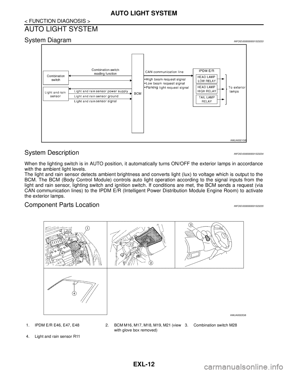
System DiagramINFOID:0000000001523233
System DescriptionINFOID:0000000001523234
When the lighting switch is in AUTO position, it automatically turns ON/OFF the exterior lamps in accordance
with the ambient light levels.
The light and rain sensor detects ambient brightness and converts light (lux) to voltage which is output to the
BCM. The BCM (Body Control Module) controls auto light operation according to the signal inputs from the
light and rain sensor, lighting switch and ignition switch. If conditions are met, the BCM sends a request (via
CAN communication lines) to the IPDM E/R (Intelligent Power Distribution Module Engine Room) to activate
the exterior lamps.
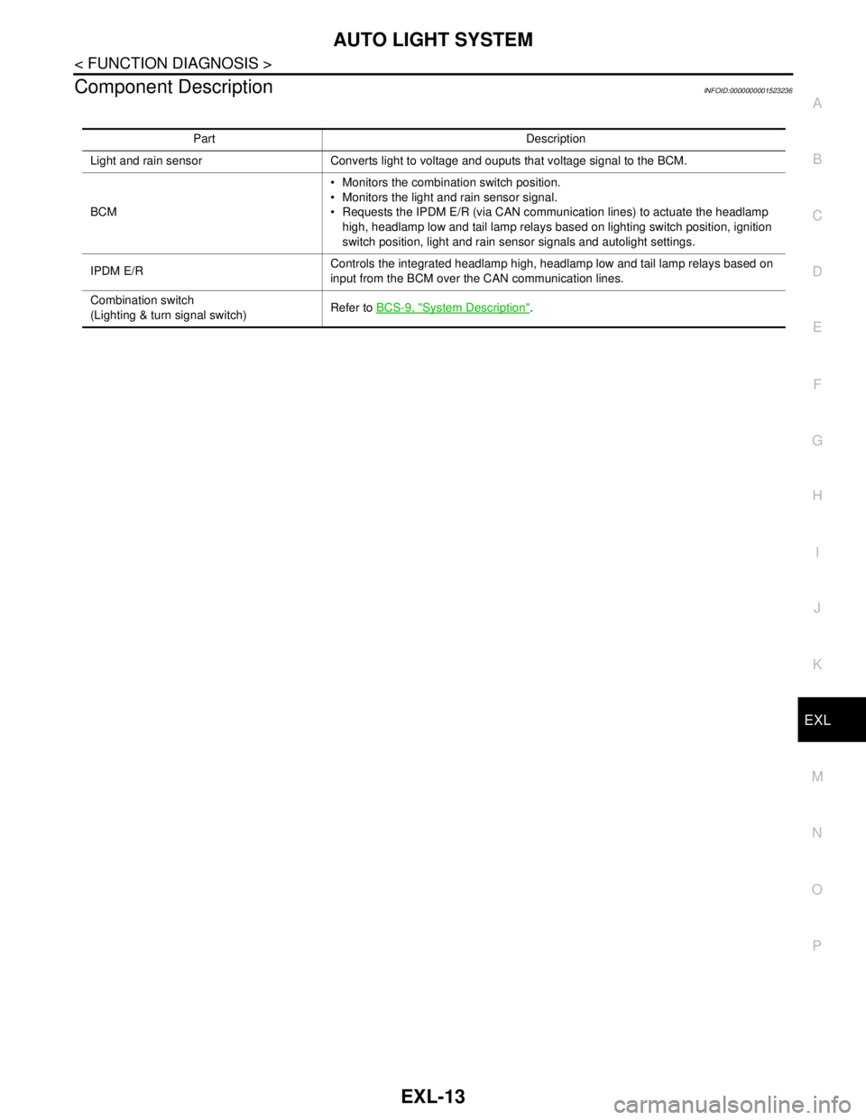
Component Parts LocationINFOID:0000000001523235
AWLIA0021GB
1. IPDM E/R E46, E47, E48 2. BCM M16, M17, M18, M19, M21 (view
with glove box removed)3. Combination switch M28
4. Light and rain sensor R11
AWLIA0022GB
Page 3014 of 5883

AUTO LIGHT SYSTEM
EXL-13
< FUNCTION DIAGNOSIS >
C
D
E
F
G
H
I
J
K
MA
B
EXL
N
O
P
Component DescriptionINFOID:0000000001523236
Part Description
Light and rain sensor Converts light to voltage and ouputs that voltage signal to the BCM.
BCM Monitors the combination switch position.
Monitors the light and rain sensor signal.
Requests the IPDM E/R (via CAN communication lines) to actuate the headlamp
high, headlamp low and tail lamp relays based on lighting switch position, ignition
switch position, light and rain sensor signals and autolight settings.
IPDM E/RControls the integrated headlamp high, headlamp low and tail lamp relays based on
input from the BCM over the CAN communication lines.
Combination switch
(Lighting & turn signal switch)Refer to BCS-9, "
System Description".
Page 3016 of 5883

HEADLAMP AIMING SYSTEM (AUTOMATIC)
EXL-15
< FUNCTION DIAGNOSIS >
C
D
E
F
G
H
I
J
K
MA
B
EXL
N
O
P
HEADLAMP AIMING SYSTEM (AUTOMATIC)
System DiagramINFOID:0000000001527658
System DescriptionINFOID:0000000001527659
The headlamp aiming system (automatic) controls the headlamp light axis height appropriately according to
the vehicle height and vehicle speed as determined by the height sensor. The height sensor controls the sig-
nal ground of the headlamp aiming motors located on the front combination lamp LH and RH.
Component Parts LocationINFOID:0000000001527660
Component DescriptionINFOID:0000000001527661
AWLIA0025GB
1. IPDM E/R E46, E47, E48 2. BCM M16, M17, M18, M19 (view
with glove box removed)3. Combination switch M28
4. Combination meter M24 5. Front combination lamp (headlamp
aiming motor)
E36 LH (shown)
E37 RH (similar)6. Height sensor B47 (view above cen-
ter of rear axle)
AWLIA0026GB