Page 3017 of 5883
EXL-16
< FUNCTION DIAGNOSIS >
HEADLAMP AIMING SYSTEM (AUTOMATIC)
Part Description
Height sensorControls the headlamp aiming motor signal ground based on vehicle height and vehicle
speed.
Headlamp aiming motorMoves the headlamp up/down based on input from the height sensor. Located in the front
combination lamp LH and RH.
Page 3028 of 5883

DIAGNOSIS SYSTEM (BCM)
EXL-27
< FUNCTION DIAGNOSIS >
C
D
E
F
G
H
I
J
K
MA
B
EXL
N
O
P
ACTIVE TEST
FLASHER
FLASHER : CONSULT-III Function (BCM - FLASHER)INFOID:0000000001528979
WORK SUPPORT
DATA MONITOR
ACTIVE TEST
LIT-SEN FAIL [OK/NOTOK] The sensor status received from light & rain sensor with serial link
The serial link condition that BCM judges
AUT LIGHT SYS [ON/OFF] Auto light system status that BCM judges from the vehicle conditionMonitor item
[Unit]Description
Test item Operation Description
TAIL LAMPONTransmits the position light request signal to IPDM E/R with CAN com-
munication to turn the tail lamp ON.
OFF Stops the tail lamp request signal transmission.
HEAD LAMPHITransmits the high beam request signal with CAN communication to turn
the headlamp (HI).
LOTransmits the low beam request signal with CAN communication to turn
the headlamp (LO).
OFF Stops the high & low beam request signal transmission.
FR FOG LAMPONTransmits the front fog lights request signal to IPDM E/R with CAN com-
munication to turn the front fog lamp ON.
OFF Stops the front fog lights request signal transmission.
RR FOG LAMPON Outputs the voltage to turn the rear fog lamp ON.
Transmits the rear fog lamp status signal to the combination meter with
CAN communication to turn the rear fog lamp indicator lamp ON.
OFF Stops the voltage to turn the rear fog lamp OFF.
Stops the rear fog lamp status signal transmission.
DAYTIME RUNNING LIGHTONTransmits the day time running light request signal to IPDM E/R with
CAN communication to turn the each lamps ON.
OFF Stops the day time running light request signal transmission.
Work Item Description
HAZARD LAMP SETOperation MODE1 MODE2 MODE3
MODE4
Keyfob operation Lock Unlock Lock Unlock Lock Unlock Lock Unlock
Hazard lamp flash - - - Twice Once - Once Twice
Monitor Item
[Unit]Description
IGN ON SW [ON/OFF] Ignition switch (ON) status judged from IGN signal (ignition power supply)
HAZARD SW [ON/OFF] The switch status input from the hazard switch
TURN SIGNAL R [ON/OFF]
Each switch condition that BCM judges from the combination switch reading function
TURN SIGNAL L [ON/OFF]
TURN/L MNTR [ON/OFF] Displays status (one bulb out: ON/other: OFF) as judged from bulb signal
Page 3032 of 5883

DIAGNOSIS SYSTEM (HEADLAMP LEVELIZER)
EXL-31
< FUNCTION DIAGNOSIS >
C
D
E
F
G
H
I
J
K
MA
B
EXL
N
O
P
DIAGNOSIS SYSTEM (HEADLAMP LEVELIZER)
CONSULT-III FunctionINFOID:0000000001530336
APPLICATION ITEM
CONSULT-III performs the following functions via CAN communication with IPDM E/R.
SELF-DIAG RESULTS
DATA MONITOR
Monitor item
ACTIVE TEST
Te s t i t e m
WORK SUPPORT
Support item
Diagnosis mode Description
SELF-DIAG RESULTS Displays the diagnosis results judged by IPDM E/R.
DATA MONITOR Displays the real-time input/output data from IPDM E/R input/output data.
ACTIVE TEST IPDM E/R can provide a drive signal to electronic components to check their operations.
CAN DIAG SUPPORT MONITOR The results of transmit/receive diagnosis of CAN communication can be read.
Error item Description Possible cause/Action to take
PARA NOT PROG [B208A] Height sensor not initialized
Initialize sensor using CONSULT-III
INITIAL NOT DONE [B2081] Height sensor not initialized
Monitor Item
[Unit]MAIN SIG-
NALSDescription
INT SEN VALUE
[%]
ACT OUTPUT
[%]
ACT MEASURED
[%]
SPEED SIG
[km/h]Displays the vehicle speed as received from the combination meter.
LIGHT SIGNAL
[V]Displays voltage of the parking lamps ON signal as received from the IPDM E/R
INT SEN VOLT
[V]Displays voltage available to the height sensor.
EXT SEN VOLT
[V]
EXT SEN SIG
[V]
Test item Operation Description
LAMP TESTMIN Operates aiming motor to lowest axis.
MID Operates aiming motor to middle axis.
MAX Operates aiming motor to highest axis.
Test item Description
SENSOR INITIALISE Adjust sensor and store initial height setting.
Page 3056 of 5883

LIGHT & RAIN SENSOR
EXL-55
< COMPONENT DIAGNOSIS >
C
D
E
F
G
H
I
J
K
MA
B
EXL
N
O
P
LIGHT & RAIN SENSOR
DescriptionINFOID:0000000001523274
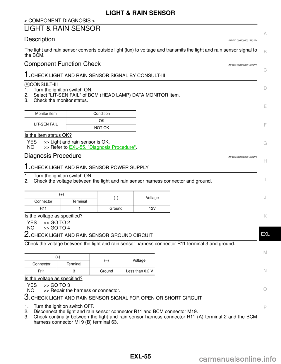
The light and rain sensor converts outside light (lux) to voltage and transmits the light and rain sensor signal to
the BCM.
Component Function CheckINFOID:0000000001523275
1.CHECK LIGHT AND RAIN SENSOR SIGNAL BY CONSULT-III
CONSULT-III
1. Turn the ignition switch ON.
2. Select "LIT-SEN FAIL" of BCM (HEAD LAMP) DATA MONITOR item.
3. Check the monitor status.
Is the item status OK?
YES >> Light and rain sensor is OK.
NO >> Refer to EXL-55, "
Diagnosis Procedure".
Diagnosis ProcedureINFOID:0000000001523276
1.CHECK LIGHT AND RAIN SENSOR POWER SUPPLY
1. Turn the ignition switch ON.
2. Check the voltage between the light and rain sensor harness connector and ground.
Is the voltage as specified?
YES >> GO TO 2
NO >> GO TO 4
2.CHECK LIGHT AND RAIN SENSOR GROUND CIRCUIT
Check the voltage between the light and rain sensor harness connector R11 terminal 3 and ground.
Is the voltage as specified?
YES >> GO TO 3
NO >> Repair the harness or connector.
3.CHECK LIGHT AND RAIN SENSOR SIGNAL FOR OPEN OR SHORT CIRCUIT
1. Turn the ignition switch OFF.
2. Disconnect the light and rain sensor connector R11 and BCM connector M19.
3. Check continuity between the light and rain sensor harness connector R11 (A) terminal 2 and the BCM
harness connector M19 (B) terminal 63.
Monitor item Condition
L I T- S E N FA I LOK
NOT OK
(+)
(−) Voltage
Connector Terminal
R11 1 Ground 12V
(+)
(−) Voltage
Connector Terminal
R11 3 Ground Less than 0.2 V
Page 3057 of 5883
EXL-56
< COMPONENT DIAGNOSIS >
LIGHT & RAIN SENSOR
4. Check continuity between the light and rain sensor harness connector R11 (A) terminal 2 and ground.
Are the continuity check results as specified?
YES >> Replace the light and rain sensor.
NO >> Repair harness or connector.
4.CHECK LIGHT AND RAIN SENSOR POWER SUPPLY FOR OPEN CIRCUIT
1. Turn the ignition switch OFF.
2. Disconnect the light and rain sensor connector R11 and BCM connector M20.
3. Check continuity between the light and rain sensor harness connector R11 (A) terminal 1 and the BCM
harness connector M20 (B) terminal 73.
jAre continuity check results as specified?
YES >> Replace the BCM.
NO >> Repair the harnesses or connectors.
AB
Continuity
Connector Terminal Connector Terminal
R11 2 M19 63 Yes
A
— Continuity
Connector Terminal
R11 2 Ground No
AB
Continuity
Connector Terminal Connector Terminal
R11 1 M20 73 Yes
Page 3074 of 5883

EXTERIOR LIGHTING SYSTEM SYMPTOMS
EXL-73
< SYMPTOM DIAGNOSIS >
C
D
E
F
G
H
I
J
K
MA
B
EXL
N
O
P
SYMPTOM DIAGNOSIS
EXTERIOR LIGHTING SYSTEM SYMPTOMS
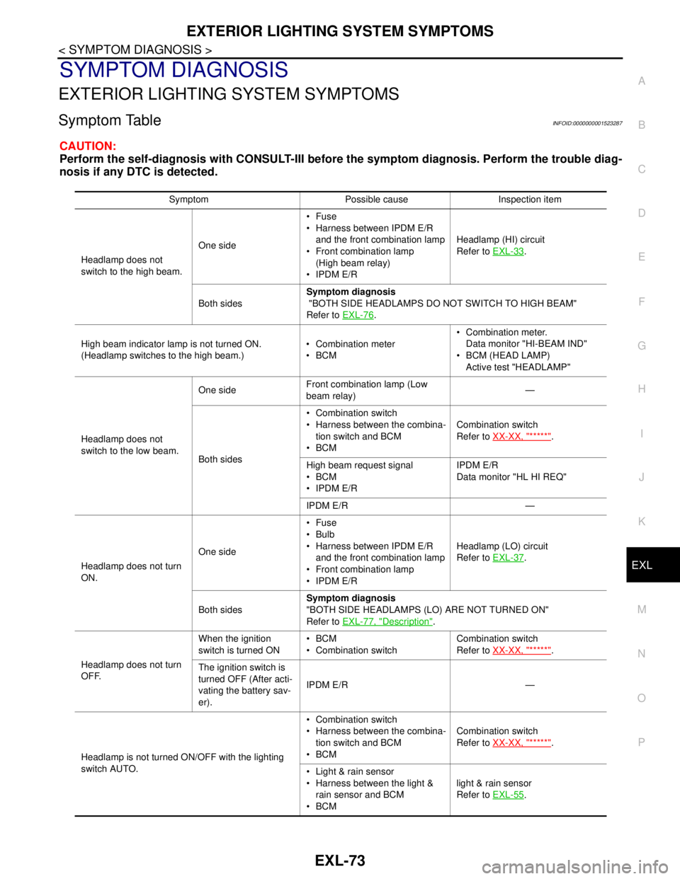
Symptom TableINFOID:0000000001523287
CAUTION:
Perform the self-diagnosis with CONSULT-III before the symptom diagnosis. Perform the trouble diag-
nosis if any DTC is detected.
Symptom Possible cause Inspection item
Headlamp does not
switch to the high beam.One sideFuse
Harness between IPDM E/R
and the front combination lamp
Front combination lamp
(High beam relay)
IPDM E/RHeadlamp (HI) circuit
Refer to EXL-33
.
Both sidesSymptom diagnosis
"BOTH SIDE HEADLAMPS DO NOT SWITCH TO HIGH BEAM"
Refer to EXL-76
.
High beam indicator lamp is not turned ON.
(Headlamp switches to the high beam.) Combination meter
BCM Combination meter.
Data monitor "HI-BEAM IND"
BCM (HEAD LAMP)
Active test "HEADLAMP"
Headlamp does not
switch to the low beam.One sideFront combination lamp (Low
beam relay)—
Both sides Combination switch
Harness between the combina-
tion switch and BCM
BCMCombination switch
Refer to XX-XX, "*****"
.
High beam request signal
BCM
IPDM E/RIPDM E/R
Data monitor "HL HI REQ"
IPDM E/R —
Headlamp does not turn
ON.One sideFuse
Bulb
Harness between IPDM E/R
and the front combination lamp
Front combination lamp
IPDM E/RHeadlamp (LO) circuit
Refer to EXL-37
.
Both sidesSymptom diagnosis
"BOTH SIDE HEADLAMPS (LO) ARE NOT TURNED ON"
Refer to EXL-77, "
Description".
Headlamp does not turn
OFF.When the ignition
switch is turned ONBCM
Combination switchCombination switch
Refer to XX-XX, "*****"
.
The ignition switch is
turned OFF (After acti-
vating the battery sav-
er).IPDM E/R —
Headlamp is not turned ON/OFF with the lighting
switch AUTO. Combination switch
Harness between the combina-
tion switch and BCM
BCMCombination switch
Refer to XX-XX, "*****"
.
Light & rain sensor
Harness between the light &
rain sensor and BCM
BCMlight & rain sensor
Refer to EXL-55
.
Page 3090 of 5883
HEADLAMP AIMING CONTROL
EXL-89
< ON-VEHICLE REPAIR >
C
D
E
F
G
H
I
J
K
MA
B
EXL
N
O
P
Removal and Installation of Height SensorINFOID:0000000001530540
REMOVAL
1. Disconnect the height sensor connector.
2. Disconnect the height sensor arm from the height sensor arm bracket.
3. Remove the height sensor bolts and remove the height sensor.
1. Tightening order 2. Tightening order 3. Height sensor
4. Height sensor arm 5. Height sensor arm bracket A. Height sensor bolt
B. Height sensor arm nut C. Height sensor arm bracket Front
ALLIA0367ZZ
Page 3091 of 5883
EXL-90
< ON-VEHICLE REPAIR >
HEADLAMP AIMING CONTROL
INSTALLATION
Installation is in the reverse order of removal.
Tighten the height sensor bolt closest to the vehicle front first when installing the height sensor.
The new height sensor must be initialized using Consult III for proper functioning of the automatic headlamp
aiming system.