2007 NISSAN TIIDA sensor
[x] Cancel search: sensorPage 3311 of 5883

REFRIGERATION SYSTEM
HA-29
< ON-VEHICLE REPAIR >
C
D
E
F
G
H
J
K
L
MA
B
HA
N
O
P
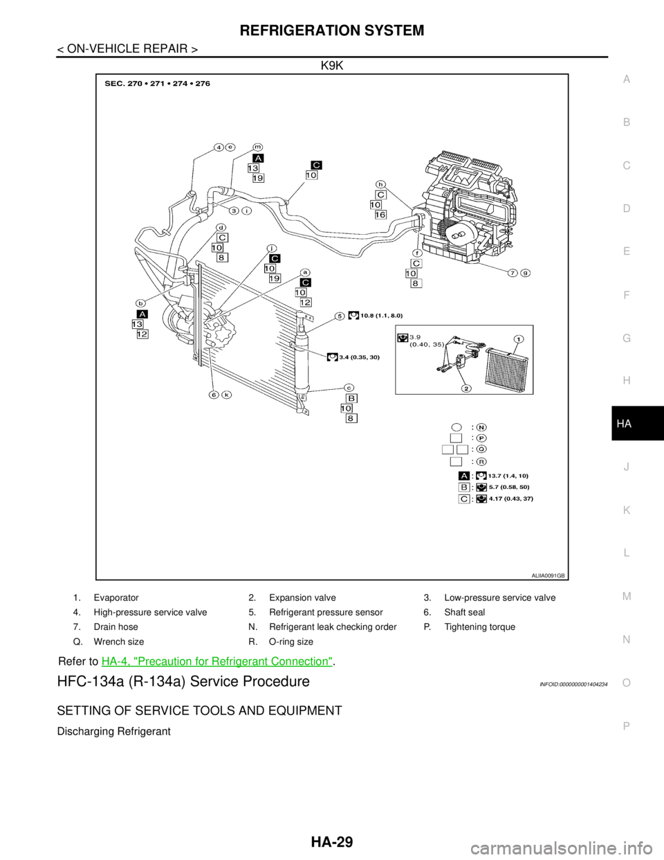
K9K
Refer to HA-4, "Precaution for Refrigerant Connection".
HFC-134a (R-134a) Service ProcedureINFOID:0000000001404234
SETTING OF SERVICE TOOLS AND EQUIPMENT
Discharging Refrigerant
ALIIA0091GB
1. Evaporator 2. Expansion valve 3. Low-pressure service valve
4. High-pressure service valve 5. Refrigerant pressure sensor 6. Shaft seal
7. Drain hose N. Refrigerant leak checking order P. Tightening torque
Q. Wrench size R. O-ring size
Page 3327 of 5883

CONDENSER
HA-45
< ON-VEHICLE REPAIR >
C
D
E
F
G
H
J
K
L
MA
B
HA
N
O
P
CONDENSER
Removal and Installation of Condenser - MR18DE, HR16DEINFOID:0000000001527646
REMOVAL
1. Use the recovery/recycling equipment to evacuate the refrigerant. Refer to HA-21, "HFC-134a (R-134a)
Service Procedure".
2. Remove the three upper headlamp bolts to reposition the headlamps out of the way
3. Remove the radiator core support upper.
4. Disconnect the high-pressure flexible hose and high-pressure pipe from condenser.
CAUTION:
Cap or wrap the joint of the pipe with suitable material such as vinyl tape to avoid the entry of air.
5. Disconnect refrigerant pressure sensor connector.
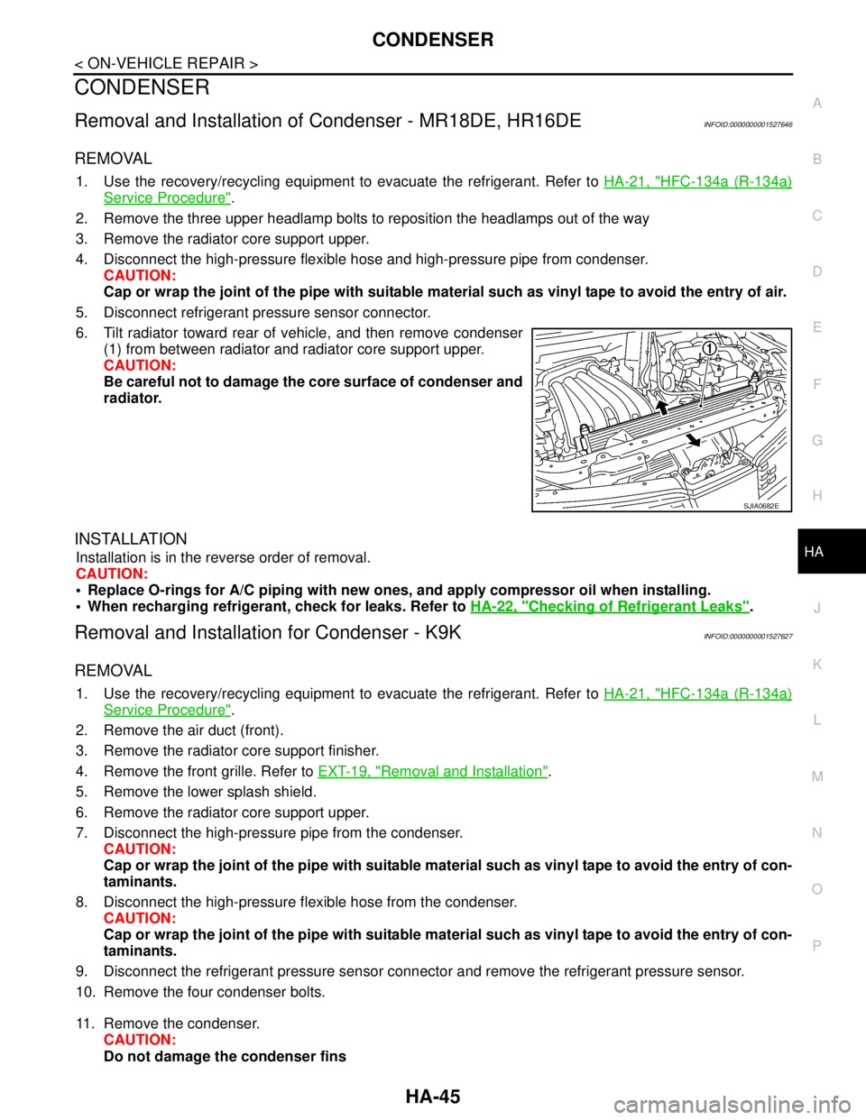
6. Tilt radiator toward rear of vehicle, and then remove condenser
(1) from between radiator and radiator core support upper.
CAUTION:
Be careful not to damage the core surface of condenser and
radiator.
INSTALLATION
Installation is in the reverse order of removal.
CAUTION:
Replace O-rings for A/C piping with new ones, and apply compressor oil when installing.
When recharging refrigerant, check for leaks. Refer to HA-22, "
Checking of Refrigerant Leaks".
Removal and Installation for Condenser - K9KINFOID:0000000001527627
REMOVAL
1. Use the recovery/recycling equipment to evacuate the refrigerant. Refer to HA-21, "HFC-134a (R-134a)
Service Procedure".
2. Remove the air duct (front).
3. Remove the radiator core support finisher.
4. Remove the front grille. Refer to EXT-19, "
Removal and Installation".
5. Remove the lower splash shield.
6. Remove the radiator core support upper.
7. Disconnect the high-pressure pipe from the condenser.
CAUTION:
Cap or wrap the joint of the pipe with suitable material such as vinyl tape to avoid the entry of con-
taminants.
8. Disconnect the high-pressure flexible hose from the condenser.
CAUTION:
Cap or wrap the joint of the pipe with suitable material such as vinyl tape to avoid the entry of con-
taminants.
9. Disconnect the refrigerant pressure sensor connector and remove the refrigerant pressure sensor.
10. Remove the four condenser bolts.
11. Remove the condenser.
CAUTION:
Do not damage the condenser fins
SJIA0682E
Page 3329 of 5883

AMBIENT SENSOR
HA-47
< ON-VEHICLE REPAIR >
C
D
E
F
G
H
J
K
L
MA
B
HA
N
O
P
AMBIENT SENSOR
Removal and Installation of Ambient Sensor - MR18DE, HR16DE and K9KINFOID:0000000001696506
NOTE:
Vehicles with automatic A/C systems and manual A/C system with a PTC heater are equipped with a ambient
sensor.
REMOVAL
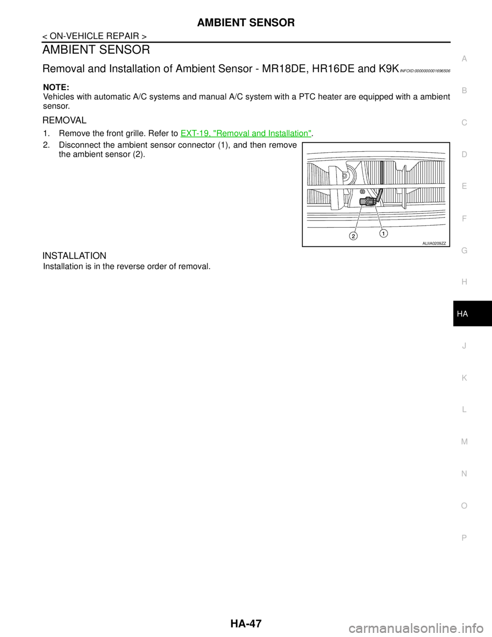
1. Remove the front grille. Refer to EXT-19, "Removal and Installation".
2. Disconnect the ambient sensor connector (1), and then remove
the ambient sensor (2).
INSTALLATION
Installation is in the reverse order of removal.
ALIIA0209ZZ
Page 3330 of 5883

HA-48
< ON-VEHICLE REPAIR >
REFRIGERANT PRESSURE SENSOR
REFRIGERANT PRESSURE SENSOR
Removal and Installation of Refrigerant Pressure Sensor - MR18DE, HR16DE
INFOID:0000000001527644
REMOVAL
1. Use the recovery/recycling equipment to evacuate the refrigerant. Refer to HA-21, "HFC-134a (R-134a)
Service Procedure".
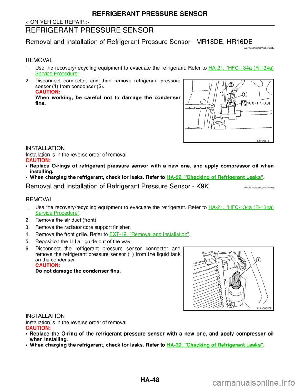
2. Disconnect connector, and then remove refrigerant pressure
sensor (1) from condenser (2).
CAUTION:
When working, be careful not to damage the condenser
fins.
INSTALLATION
Installation is in the reverse order of removal.
CAUTION:
Replace O-rings of refrigerant pressure sensor with a new one, and apply compressor oil when
installing.
When charging the refrigerant, check for leaks. Refer to HA-22, "
Checking of Refrigerant Leaks".
Removal and Installation of Refrigerant Pressure Sensor - K9KINFOID:0000000001527628
REMOVAL
1. Use the recovery/recycling equipment to evacuate the refrigerant. Refer to HA-21, "HFC-134a (R-134a)
Service Procedure".
2. Remove the air duct (front).
3. Remove the radiator core support finisher.
4. Remove the front grille. Refer to EXT-19, "
Removal and Installation".
5. Reposition the LH air guide out of the way.
6. Disconnect the refrigerant pressure sensor connector and
remove the refrigerant pressure sensor (1) from the liquid tank
on the condenser.
CAUTION:
Do not damage the condenser fins.
INSTALLATION
Installation is in the reverse order of removal.
CAUTION:
Replace the O-ring of the refrigerant pressure sensor with a new one, and apply compressor oil
when installing.
When charging the refrigerant, check for leaks. Refer to HA-22, "
Checking of Refrigerant Leaks".
SJIA0681E
ALIIA0004ZZ
Page 3334 of 5883

HAC-1
VENTILATION, HEATER & AIR CONDITIONER
C
D
E
F
G
H
J
K
L
M
SECTION HAC
A
B
HAC
N
O
P
CONTENTS
HEATER & AIR CONDITIONING CONTROL SYSTEM
MANUAL AIR CONDITIONER
BASIC INSPECTION ....................................
5
DIAGNOSIS AND REPAIR WORKFLOW ..........5
How to Perform Trouble Diagnosis For Quick and
Accurate Repair ........................................................
5
INSPECTION AND ADJUSTMENT .....................6
Operational Check ....................................................6
FUNCTION DIAGNOSIS ...............................8
FUNCTION INFORMATION ................................8
Component Part Location .........................................8
REFRIGERATION SYSTEM ..............................10
Refrigerant Cycle ....................................................10
Refrigerant System Protection ................................10
AIR CONDITIONER CONTROL .........................11
System Diagram ......................................................11
System Description .................................................11
Discharge Air Flow ..................................................11
Switches And Their Control Function ......................12
Component Description ...........................................13
CAN COMMUNICATION SYSTEM ....................14
System Description .................................................14
DIAGNOSIS SYSTEM (BCM) ............................15
CONSULT-III Function (BCM) .................................15
COMPONENT DIAGNOSIS .........................16
MODE DOOR .....................................................16
Mode Door Diagnostic Procedure ...........................16
AIR MIX DOOR ...................................................17
Air Mix Door Diagnostic Procedure .........................17
INTAKE DOOR ...................................................18
Intake Door Diagnostic Procedure ..........................18
BLOWER MOTOR ............................................19
Front Blower Motor Component Function Check ....19
Front Blower Motor Diagnosis Procedure ................19
MAGNET CLUTCH ...........................................23
System Description ..................................................23
Magnet Clutch Component Function Check ............23
Magnet Clutch Diagnosis Procedure .......................24
INTAKE SENSOR .............................................30
Component Inspection .............................................30
Intake Sensor Diagnosis Procedure ........................30
Intake Sensor Component Inspection .....................31
PTC HEATER CONTROL SYSTEM .................33
PTC HEATER (300 WATT) ........................................33
PTC HEATER (300 WATT) : PTC Heater System
Description ...............................................................
33
PTC HEATER (300 WATT) : PTC Heater Compo-
nent Description .......................................................
34
PTC HEATER (300 WATT) : PTC Heater (300
Watt) Diagnosis Procedure ......................................
35
PTC HEATER (300 WATT) : PTC Heater (300
Watt) Component Inspection ...................................
41
PTC HEATER (1500 WATT) ......................................43
PTC HEATER (1500 WATT) : System Description ....43
PTC HEATER (1500 WATT) : Component De-
scription ...................................................................
44
PTC HEATER (1500 WATT) : PTC Heater (1500
Watt) Diagnosis Procedure ......................................
45
PTC HEATER (1500 WATT) : PTC Heater (1500
Watt) Component Inspection ...................................
50
ECU DIAGNOSIS .........................................53
AIR CONDITIONER CONTROL ........................53
Reference Value ......................................................53
Wiring Diagram - Heater Control (without A/C) - .....54
Wiring Diagram - Air Conditioner Control - ..............56
Page 3335 of 5883

HAC-2
PTC HEATER CONTROL SYSTEM ..................63
PTC HEATER (300 WATT) .......................................63
PTC HEATER (300 WATT) : Wiring Diagram -
PTC Heater (300 Watt) - .........................................
63
PTC HEATER (1500 WATT) .....................................67
PTC HEATER (1500 WATT) : Wiring Diagram -
PTC Heater (1500 Watt) - .......................................
68
SYMPTOM DIAGNOSIS .............................72
AIR CONDITIONER CONTROL ........................72
Symptom Matrix Chart ..........................................72
INSUFFICIENT COOLING .................................73
Component Function Check ...................................73
Performance Test Diagnoses .................................74
Performance Chart .................................................75
Test Reading ..........................................................76
Trouble Diagnoses for Unusual Pressure ...............77
INSUFFICIENT HEATING .................................81
Component Function Check ...................................81
NOISE ................................................................83
Component Function Check ...................................83
PRECAUTION .............................................84
PRECAUTIONS .................................................84
Precaution for Supplemental Restraint System
(SRS) "AIR BAG" and "SEAT BELT PRE-TEN-
SIONER" .................................................................
84
Precaution for Procedures Without Cowl Top Cov-
er ............................................................................
84
Working with HFC-134a (R-134a) ..........................84
Precaution for Service Equipment ..........................85
AUTO AIR CONDITIONER (W/O NAVI)
BASIC INSPECTION ...................................
86
DIAGNOSIS AND REPAIR WORKFLOW .........86
How to Perform Trouble Diagnosis For Quick And
Accurate Repair ......................................................
86
INSPECTION AND ADJUSTMENT ...................87
Operational Check ..................................................87
FUNCTION DIAGNOSIS .............................89
FUNCTION INFORMATION ..............................89
Component Part Location .......................................89
REFRIGERATION SYSTEM ..............................91
Refrigerant Cycle ....................................................91
Refrigerant System Protection ................................91
AUTOMATIC AIR CONDITIONER SYSTEM .....92
Control System Diagram ........................................92
Control System Description ....................................92
Discharge Air Flow .................................................94
Switches And Their Control Function ......................95
CAN COMMUNICATION SYSTEM ...................96
System Description .................................................96
DIAGNOSIS SYSTEM (BCM) ............................97
CONSULT-III Function (BCM) ................................97
SELF-DIAGNOSIS FUNCTION .........................98
Front Air Control Self-Diagnosis .............................98
A/C System Self-Diagnosis Code Chart ...............104
COMPONENT DIAGNOSIS ......................106
MODE DOOR MOTOR .....................................106
System Description ...............................................106
Mode Door Motor Component Function Check ....107
Mode Door Motor Diagnosis Procedure ................109
AIR MIX DOOR MOTOR ..................................110
System Description ...............................................110
Air Mix Door Motor Component Function Check ..111
Air Mix Door Motor Diagnosis Procedure ..............112
INTAKE DOOR MOTOR ...................................114
System Description ...............................................114
Intake Door Motor Component Function Check ....115
Intake Door Motor Diagnosis Procedure ...............116
BLOWER MOTOR CONTROL SYSTEM .........118
System Description ...............................................118
Front Blower Motor Component Function Check ..119
Front Blower Motor Diagnosis Procedure .............120
Front Blower Motor Component Inspection ..........123
MAGNET CLUTCH ...........................................124
System Description ...............................................124
Magnet Clutch Component Function Check .........124
Magnet Clutch Diagnosis Procedure ....................125
AMBIENT SENSOR ..........................................130
Component Description ........................................130
Ambient Sensor Diagnosis Procedure ..................130
Ambient Sensor Component Inspection ...............131
IN-VEHICLE SENSOR ......................................133
Component Description ........................................133
In-Vehicle Sensor Diagnosis Procedure ...............133
In-Vehicle Sensor Component Inspection .............135
SUNLOAD SENSOR ........................................136
System Description ...............................................136
Sunload Sensor Diagnosis Procedure ..................136
Sunload Component Inspection ............................137
INTAKE SENSOR .............................................139
Component Inspection ..........................................139
Intake Sensor Diagnosis Procedure .....................139
Intake Sensor Component Inspection ...................140
PTC HEATER CONTROL SYSTEM .................142
Page 3337 of 5883

HAC-4
INTAKE DOOR MOTOR ..................................228
System Description ................................................228
Intake Door Motor Component Function Check ....229
Intake Door Motor Diagnosis Procedure ...............230
BLOWER MOTOR CONTROL SYSTEM ........232
System Description ................................................232
Front Blower Motor Component Function Check ...233
Front Blower Motor Diagnosis Procedure ..............234
Front Blower Motor Component Inspection ...........236
MAGNET CLUTCH ..........................................238
System Description ................................................238
Magnet Clutch Component Function Check ..........238
Magnet Clutch Diagnosis Procedure .....................239
AMBIENT SENSOR .........................................244
Component Description .........................................244
Ambient Sensor Diagnosis Procedure ...................244
Ambient Sensor Component Inspection ................245
IN-VEHICLE SENSOR .....................................247
Component Description .........................................247
In-Vehicle Sensor Diagnosis Procedure ................247
In-Vehicle Sensor Component Inspection .............249
SUNLOAD SENSOR .......................................250
Component Description .........................................250
Sunload Sensor Diagnosis Procedure ...................250
Sunload Sensor Component Inspection ................251
INTAKE SENSOR ............................................253
System Description ................................................253
Intake Sensor Diagnosis Procedure ......................253
Intake Sensor Component Inspection ...................254
PTC HEATER CONTROL SYSTEM ................256
PTC HEATER (300 WATT) ......................................256
PTC HEATER (300 WATT) : PTC Heater System
Description .............................................................
256
PTC HEATER (300 WATT) : PTC Heater Compo-
nent Description .....................................................
257
PTC HEATER (300 WATT) : PTC Heater (300
Watt) Diagnosis Procedure ....................................
258
PTC HEATER (300 WATT) : PTC Heater (300
Watt) Component Inspection .................................
265
PTC HEATER (1500 WATT) ....................................267
PTC HEATER (1500 WATT) : System Description ..267
PTC HEATER (1500 WATT) : Component De-
scription .................................................................
268
PTC HEATER (1500 WATT) : PTC Heater (1500
Watt) Diagnosis Procedure ....................................
269
PTC HEATER (1500 WATT) : PTC Heater (1500
Watt) Component Inspection .................................
274
POWER SUPPLY AND GROUND CIRCUIT
FOR CONTROLLER .........................................
277
Component Description ........................................277
A/C Auto Amp. Component Function Check .........277
A/C Auto Amp Power and Ground Diagnosis Pro-
cedure ...................................................................
278
ECU DIAGNOSIS ......................................279
AIR CONDITIONER CONTROL .......................279
Front Air Control Terminals Reference Values .....279
Wiring Diagram - Air Conditioner Control - ...........281
PTC HEATER CONTROL SYSTEM .................289
PTC HEATER (300 WATT) .....................................289
PTC HEATER (300 WATT) : Wiring Diagram -
PTC Heater (300 Watt) - .......................................
289
PTC HEATER (1500 WATT) ...................................293
PTC HEATER (1500 WATT) : Wiring Diagram -
PTC Heater (1500 Watt) - .....................................
294
SYMPTOM DIAGNOSIS ...........................298
AIR CONDITIONER CONTROL .......................298
Symptom Matrix Chart .........................................298
INSUFFICIENT COOLING ................................299
Component Function Check .................................299
Performance Test Diagnoses ...............................300
Performance Chart ................................................302
Test Reading .........................................................303
Trouble Diagnoses for Unusual Pressure .............303
INSUFFICIENT HEATING ................................307
Component Function Check .................................307
NOISE ...............................................................309
Component Function Check .................................309
SELF-DIAGNOSIS CANNOT BE PER-
FORMED ...........................................................
311
Self-Diagnosis .......................................................311
MEMORY FUNCTION DOES NOT OPERATE ..312
Memory Function Check .......................................312
PRECAUTION ...........................................313
PRECAUTIONS ................................................313
Precaution for Supplemental Restraint System
(SRS) "AIR BAG" and "SEAT BELT PRE-TEN-
SIONER" ...............................................................
313
Precaution for Procedures Without Cowl Top Cov-
er ...........................................................................
313
Working with HFC-134a (R-134a) .........................313
Precaution for Service Equipment ........................314
Page 3341 of 5883
![NISSAN TIIDA 2007 Service Repair Manual HAC-8
< FUNCTION DIAGNOSIS >[MANUAL AIR CONDITIONER]
FUNCTION INFORMATION
FUNCTION DIAGNOSIS
FUNCTION INFORMATION
Component Part LocationINFOID:0000000001203053
ENGINE COMPARTMENT
PASSENGER COMPARTMEN NISSAN TIIDA 2007 Service Repair Manual HAC-8
< FUNCTION DIAGNOSIS >[MANUAL AIR CONDITIONER]
FUNCTION INFORMATION
FUNCTION DIAGNOSIS
FUNCTION INFORMATION
Component Part LocationINFOID:0000000001203053
ENGINE COMPARTMENT
PASSENGER COMPARTMEN](/manual-img/5/57395/w960_57395-3340.png)
HAC-8
< FUNCTION DIAGNOSIS >[MANUAL AIR CONDITIONER]
FUNCTION INFORMATION
FUNCTION DIAGNOSIS
FUNCTION INFORMATION
Component Part LocationINFOID:0000000001203053
ENGINE COMPARTMENT
PASSENGER COMPARTMENT
WJIA2235E
1. Refrigerant pressure sensor E17 (if
equipped)2. A/C compressor F3 (if equipped)