2007 NISSAN TIIDA front
[x] Cancel search: frontPage 4589 of 5883
INSPECTION
SB-5
< BASIC INSPECTION >
C
D
E
F
G
I
J
K
L
MA
B
SB
N
O
P
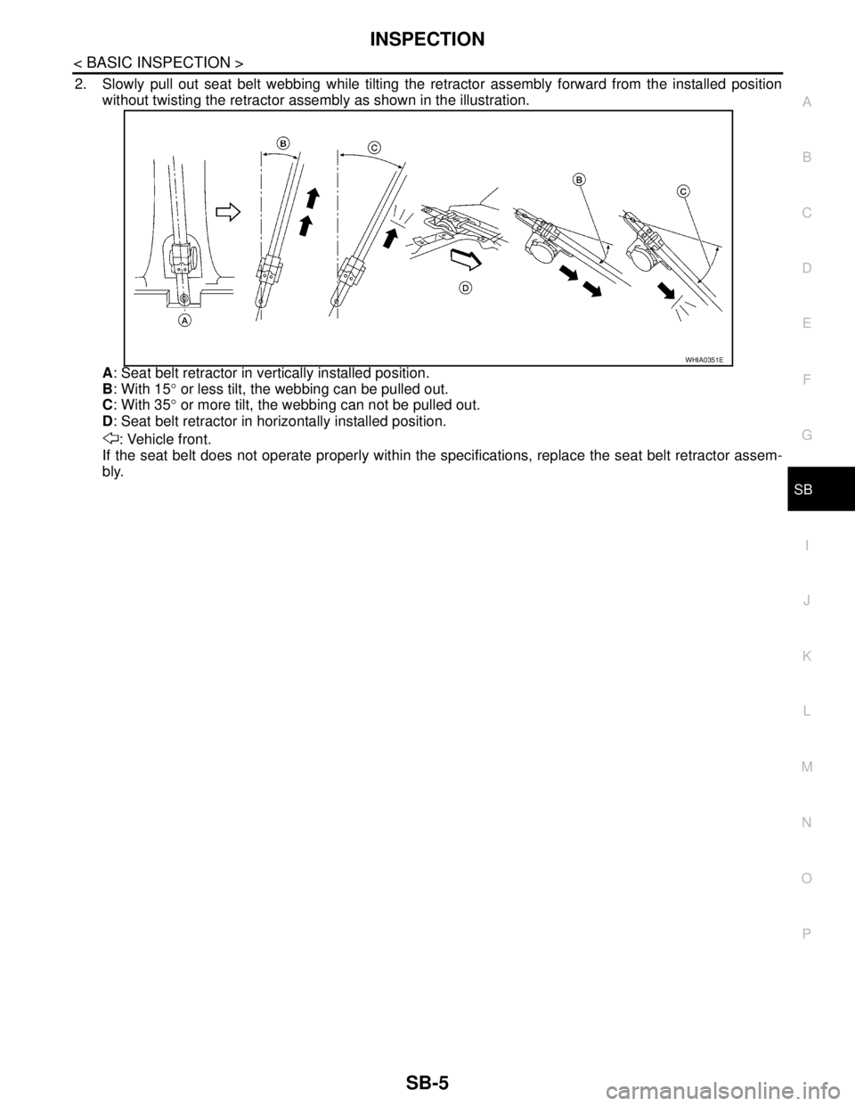
2. Slowly pull out seat belt webbing while tilting the retractor assembly forward from the installed position
without twisting the retractor assembly as shown in the illustration.
A: Seat belt retractor in vertically installed position.
B: With 15° or less tilt, the webbing can be pulled out.
C: With 35° or more tilt, the webbing can not be pulled out.
D: Seat belt retractor in horizontally installed position.
: Vehicle front.
If the seat belt does not operate properly within the specifications, replace the seat belt retractor assem-
bly.
WHIA0351E
Page 4590 of 5883
SB-6
< ON-VEHICLE REPAIR >
FRONT SEAT BELT
ON-VEHICLE REPAIR
FRONT SEAT BELT
Removal and Installation of Front Seat BeltINFOID:0000000001396419
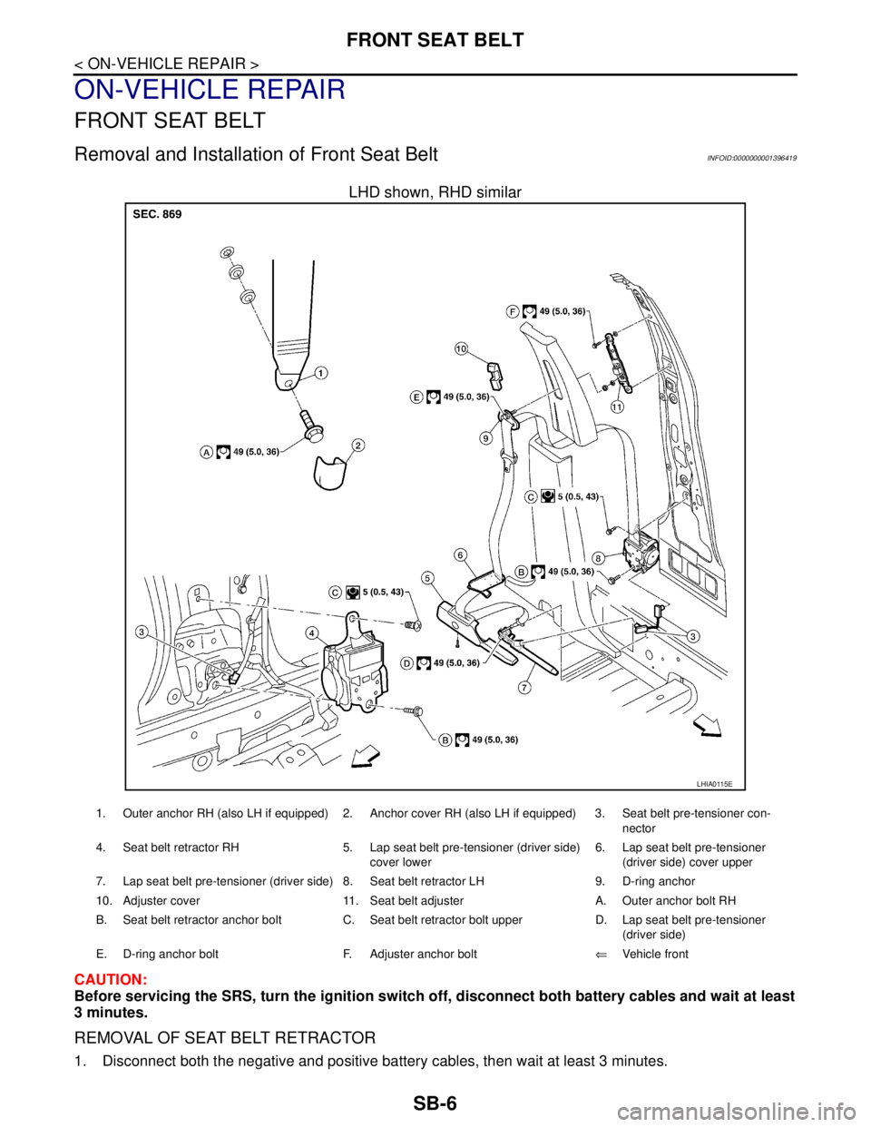
LHD shown, RHD similar
CAUTION:
Before servicing the SRS, turn the ignition switch off, disconnect both battery cables and wait at least
3 minutes.
REMOVAL OF SEAT BELT RETRACTOR
1. Disconnect both the negative and positive battery cables, then wait at least 3 minutes.
LHIA0115E
1. Outer anchor RH (also LH if equipped) 2. Anchor cover RH (also LH if equipped) 3. Seat belt pre-tensioner con-
nector
4. Seat belt retractor RH 5. Lap seat belt pre-tensioner (driver side)
cover lower6. Lap seat belt pre-tensioner
(driver side) cover upper
7. Lap seat belt pre-tensioner (driver side) 8. Seat belt retractor LH 9. D-ring anchor
10. Adjuster cover 11. Seat belt adjuster A. Outer anchor bolt RH
B. Seat belt retractor anchor bolt C. Seat belt retractor bolt upper D. Lap seat belt pre-tensioner
(driver side)
E. D-ring anchor bolt F. Adjuster anchor bolt⇐Vehicle front
Page 4591 of 5883
FRONT SEAT BELT
SB-7
< ON-VEHICLE REPAIR >
C
D
E
F
G
I
J
K
L
MA
B
SB
N
O
P
2. Remove the adjuster cover and D-ring anchor bolt.
3. Remove both the center pillar upper and lower garnish. Refer to INT-20, "
Removal and Installation".
WARNING:
Do not reuse center pillar upper garnish if removed.
4. Pull the floor trim away from center pillar.
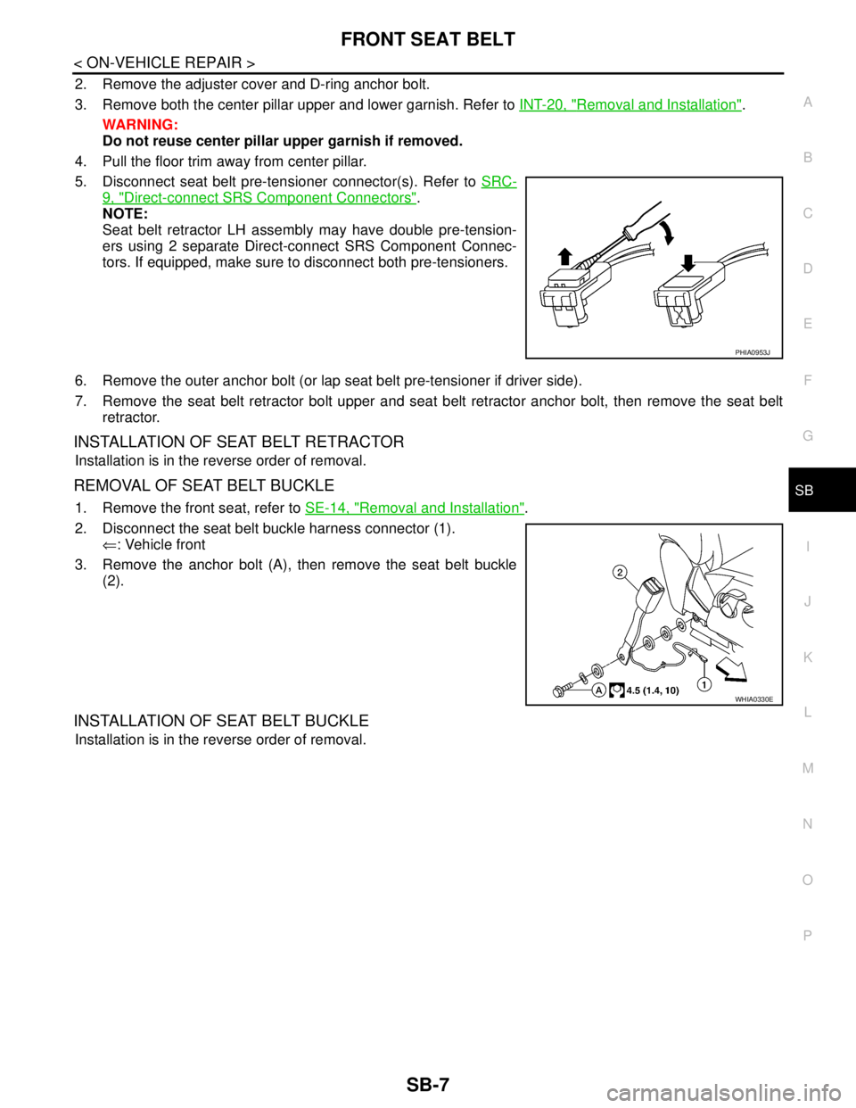
5. Disconnect seat belt pre-tensioner connector(s). Refer to SRC-
9, "Direct-connect SRS Component Connectors".
NOTE:
Seat belt retractor LH assembly may have double pre-tension-
ers using 2 separate Direct-connect SRS Component Connec-
tors. If equipped, make sure to disconnect both pre-tensioners.
6. Remove the outer anchor bolt (or lap seat belt pre-tensioner if driver side).
7. Remove the seat belt retractor bolt upper and seat belt retractor anchor bolt, then remove the seat belt
retractor.
INSTALLATION OF SEAT BELT RETRACTOR
Installation is in the reverse order of removal.
REMOVAL OF SEAT BELT BUCKLE
1. Remove the front seat, refer to SE-14, "Removal and Installation".
2. Disconnect the seat belt buckle harness connector (1).
⇐: Vehicle front
3. Remove the anchor bolt (A), then remove the seat belt buckle
(2).
INSTALLATION OF SEAT BELT BUCKLE
Installation is in the reverse order of removal.
PHIA0953J
WHIA0330E
Page 4593 of 5883
REAR SEAT BELT
SB-9
< ON-VEHICLE REPAIR >
C
D
E
F
G
I
J
K
L
MA
B
SB
N
O
P
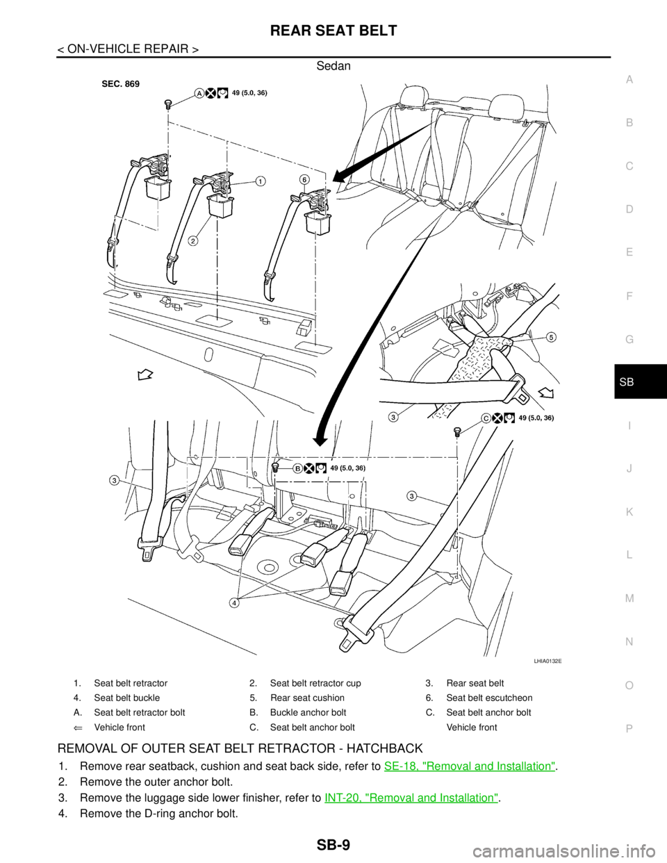
Sedan
REMOVAL OF OUTER SEAT BELT RETRACTOR - HATCHBACK
1. Remove rear seatback, cushion and seat back side, refer to SE-18, "Removal and Installation".
2. Remove the outer anchor bolt.
3. Remove the luggage side lower finisher, refer to INT-20, "
Removal and Installation".
4. Remove the D-ring anchor bolt.
LHIA0132E
1. Seat belt retractor 2. Seat belt retractor cup 3. Rear seat belt
4. Seat belt buckle 5. Rear seat cushion 6. Seat belt escutcheon
A. Seat belt retractor bolt B. Buckle anchor bolt C. Seat belt anchor bolt
⇐Vehicle front C. Seat belt anchor bolt Vehicle front
Page 4594 of 5883
SB-10
< ON-VEHICLE REPAIR >
REAR SEAT BELT
5. Remove the outer retractor anchor bolt, then remove outer seat belt retractor.
INSTALLATION OF OUTER SEAT BELT RETRACTOR - HATCHBACK
Installation is in the reverse order of removal.
REMOVAL OF OUTER SEAT BELT RETRACTOR - SEDAN
1. Remove rear seat cushion, refer to SE-18, "Removal and Installation".
2. Remove outer seat belt anchor bolt.
3. Release the seat belt escutcheon, then remove from belt.
4. Remove rear parcel shelf finisher, refer to INT-26, "
Removal and Installation".
5. Remove outer seat belt retractor bolt, then remove outer seat belt retractor.
INSTALLATION OF OUTER SEAT BELT RETRACTOR - SEDAN
Installation is in the reverse order of removal.
REMOVAL OF CENTER SEAT BELT RETRACTOR - HATCHBACK
1. Remove and disassemble the rear seat cushion, refer to SE-18, "Removal and Installation".
2. Remove the center seat belt retractor.
INSTALLATION OF CENTER SEAT BELT RETRACTOR - HATCHBACK
Installation is in the reverse order of removal.
REMOVAL OF CENTER SEAT BELT RETRACTOR - SEDAN
1. Lift front edge of rear seat cushion and slide forward.
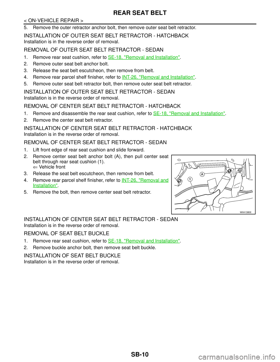
2. Remove center seat belt anchor bolt (A), then pull center seat
belt through rear seat cushion (1).
⇐ Vehicle front
3. Release the seat belt escutcheon, then remove from belt.
4. Remove rear parcel shelf finisher, refer to INT-26, "
Removal and
Installation".
5. Remove the bolt, then remove center seat belt retractor.
INSTALLATION OF CENTER SEAT BELT RETRACTOR - SEDAN
Installation is in the reverse order of removal.
REMOVAL OF SEAT BELT BUCKLE
1. Remove rear seat cushion, refer to SE-18, "Removal and Installation".
2. Remove buckle anchor bolt, then remove seat belt buckle.
INSTALLATION OF SEAT BELT BUCKLE
Installation is in the reverse order of removal.
WIIA1380E
Page 4597 of 5883
SE-1
BODY INTERIOR
C
D
E
F
G
H
I
K
L
M
SECTION SE
A
B
SE
N
O
P
CONTENTS
SEAT
COMPONENT DIAGNOSIS ..........................2
HEATED SEAT ....................................................2
Wiring Diagram .........................................................2
SYMPTOM DIAGNOSIS ...............................5
SQUEAK AND RATTLE TROUBLE DIAG-
NOSES ................................................................
5
Work Flow .................................................................5
Generic Squeak and Rattle Troubleshooting ............7
Diagnostic Worksheet ...............................................9
PRECAUTION ..............................................11
PRECAUTIONS ..................................................11
Precaution for Supplemental Restraint System
(SRS) "AIR BAG" and "SEAT BELT PRE-TEN-
SIONER" .................................................................
11
PREPARATION ...........................................12
PREPARATION ..................................................12
Special Service Tool ...............................................12
Commercial Service Tool ........................................12
REMOVAL AND INSTALLATION ...............13
FRONT SEAT ....................................................13
Exploded View .........................................................13
Removal and Installation .........................................14
REAR SEAT ......................................................16
Exploded View .........................................................16
Removal and Installation .........................................18
Removal and Installation .........................................20
ON-VEHICLE REPAIR .................................21
FRONT SEAT ....................................................21
Exploded View .........................................................21
Disassembly and Assembly .....................................22
REAR SEAT ......................................................24
Exploded View .........................................................24
Disassembly and Assembly .....................................26
Disassembly and Assembly .....................................27
Page 4603 of 5883
SQUEAK AND RATTLE TROUBLE DIAGNOSES
SE-7
< SYMPTOM DIAGNOSIS >
C
D
E
F
G
H
I
K
L
MA
B
SE
N
O
P
68370-4B000: 15×25 mm (0.59×0.98 in) pad/68239-13E00: 5 mm (0.20 in) wide tape roll. The following
materials not found in the kit can also be used to repair squeaks and rattles.
UHMW (TEFLON) TAPE
Insulates where slight movement is present. Ideal for instrument panel applications.
SILICONE GREASE
Used instead of UHMW tape that will be visible or not fit.
Note: Will only last a few months.
SILICONE SPRAY
Use when grease cannot be applied.
DUCT TAPE
Use to eliminate movement.
CONFIRM THE REPAIR
Confirm that the cause of a noise is repaired by test driving the vehicle. Operate the vehicle under the same
conditions as when the noise originally occurred. Refer to the notes on the Diagnostic Worksheet.
Generic Squeak and Rattle TroubleshootingINFOID:0000000001710923
Refer to Table of Contents for specific component removal and installation information.
INSTRUMENT PANEL
Most incidents are caused by contact and movement between:
1. The cluster lid A and instrument panel
2. Acrylic lens and combination meter housing
3. Instrument panel to front pillar garnish
4. Instrument panel to windshield
5. Instrument panel mounting pins
6. Wiring harnesses behind the combination meter
7. A/C defroster duct and duct joint
These incidents can usually be located by tapping or moving the components to duplicate the noise or by
pressing on the components while driving to stop the noise. Most of these incidents can be repaired by apply-
ing felt cloth tape or silicone spray (in hard to reach areas). Urethane pads can be used to insulate wiring har-
ness.
CAUTION:
Do not use silicone spray to isolate a squeak or rattle. If you saturate the area with silicone, you will
not be able to recheck the repair.
CENTER CONSOLE
Components to pay attention to include:
1. Shifter assembly cover to finisher
2. A/C control unit and cluster lid C
3. Wiring harnesses behind audio and A/C control unit
The instrument panel repair and isolation procedures also apply to the center console.
DOORS
Pay attention to the:
1. Finisher and inner panel making a slapping noise
2. Inside handle escutcheon to door finisher
3. Wiring harnesses tapping
4. Door striker out of alignment causing a popping noise on starts and stops
Tapping or moving the components or pressing on them while driving to duplicate the conditions can isolate
many of these incidents. You can usually insulate the areas with felt cloth tape or insulator foam blocks from
the NISSAN Squeak and Rattle Kit (J-43980) to repair the noise.
TRUNK
Trunk noises are often caused by a loose jack or loose items put into the trunk by the owner.
In addition look for:
1. Trunk lid bumpers out of adjustment
Page 4604 of 5883

SE-8
< SYMPTOM DIAGNOSIS >
SQUEAK AND RATTLE TROUBLE DIAGNOSES
2. Trunk lid striker out of adjustment
3. The trunk lid torsion bars knocking together
4. A loose license plate or bracket
Most of these incidents can be repaired by adjusting, securing or insulating the item(s) or component(s) caus-
ing the noise.
SUNROOF/HEADLINING
Noises in the sunroof/headlining area can often be traced to one of the following:
1. Sunroof lid, rail, linkage or seals making a rattle or light knocking noise
2. Sun visor shaft shaking in the holder
3. Front or rear windshield touching headliner and squeaking
Again, pressing on the components to stop the noise while duplicating the conditions can isolate most of these
incidents. Repairs usually consist of insulating with felt cloth tape.
OVERHEAD CONSOLE (FRONT AND REAR)
Overhead console noises are often caused by the console panel clips not being engaged correctly. Most of
these incidents are repaired by pushing up on the console at the clip locations until the clips engage.
In addition look for:
1. Loose harness or harness connectors.
2. Front console map/reading lamp lense loose.
3. Loose screws at console attachment points.
SEATS
When isolating seat noise it's important to note the position the seat is in and the load placed on the seat when
the noise is present. These conditions should be duplicated when verifying and isolating the cause of the
noise.
Cause of seat noise include:
1. Headrest rods and holder
2. A squeak between the seat pad cushion and frame
3. The rear seatback lock and bracket
These noises can be isolated by moving or pressing on the suspected components while duplicating the con-
ditions under which the noise occurs. Most of these incidents can be repaired by repositioning the component
or applying urethane tape to the contact area.
UNDERHOOD
Some interior noise may be caused by components under the hood or on the engine wall. The noise is then
transmitted into the passenger compartment.
Causes of transmitted underhood noise include:
1. Any component mounted to the engine wall
2. Components that pass through the engine wall
3. Engine wall mounts and connectors
4. Loose radiator mounting pins
5. Hood bumpers out of adjustment
6. Hood striker out of adjustment
These noises can be difficult to isolate since they cannot be reached from the interior of the vehicle. The best
method is to secure, move or insulate one component at a time and test drive the vehicle. Also, engine RPM
or load can be changed to isolate the noise. Repairs can usually be made by moving, adjusting, securing, or
insulating the component causing the noise.