2007 NISSAN TIIDA front
[x] Cancel search: frontPage 4619 of 5883

FRONT SEAT
SE-23
< ON-VEHICLE REPAIR >
C
D
E
F
G
H
I
K
L
MA
B
SE
N
O
P
2. Remove the hog rings to separate the seat cushion pad and seat cushion trim.
3. Remove seat cushion trim and seat cushion pad from the seat cushion frame.
Assembly
Assembly is the reverse order of removal.
SEAT CUSHION FRAME
Disassembly
1. Remove the seat cushion trim and pad. Refer to "SEAT CUSHION TRIM AND PAD" .
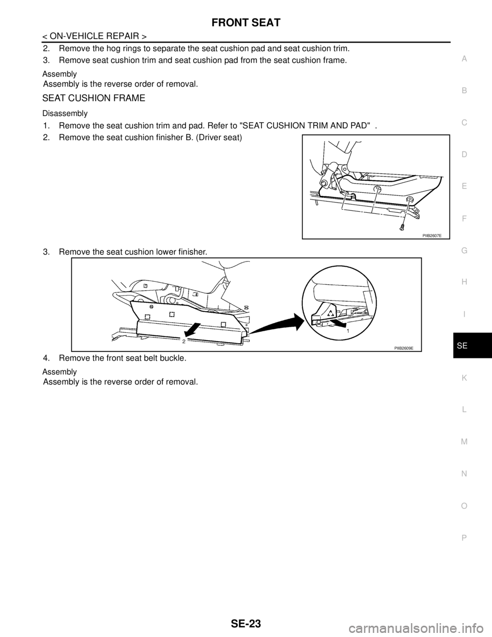
2. Remove the seat cushion finisher B. (Driver seat)
3. Remove the seat cushion lower finisher.
4. Remove the front seat belt buckle.
Assembly
Assembly is the reverse order of removal.
PIIB2607E
PIIB2609E
Page 4621 of 5883

REAR SEAT
SE-25
< ON-VEHICLE REPAIR >
C
D
E
F
G
H
I
K
L
MA
B
SE
N
O
P
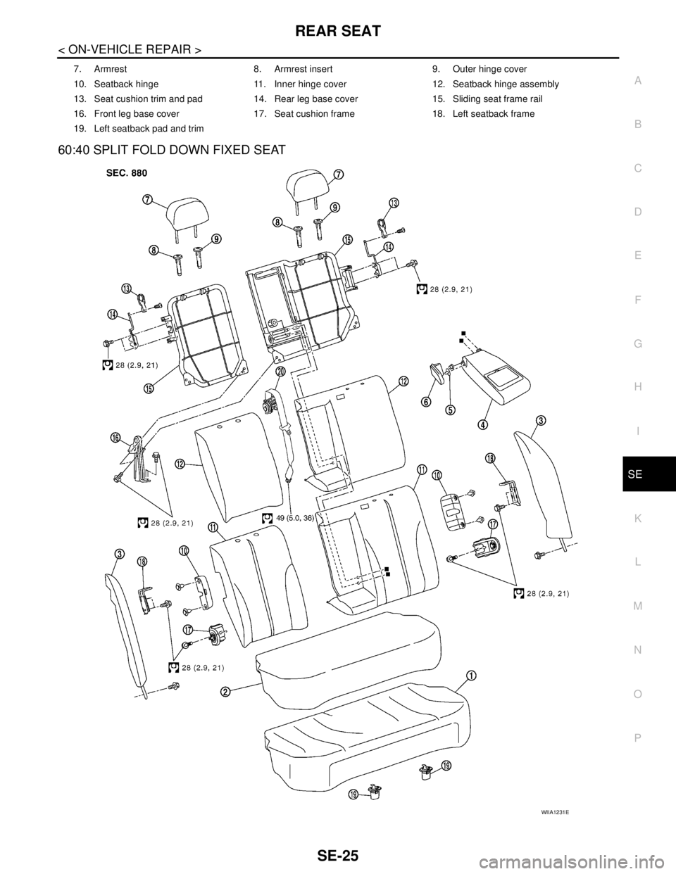
60:40 SPLIT FOLD DOWN FIXED SEAT
7. Armrest 8. Armrest insert 9. Outer hinge cover
10. Seatback hinge 11. Inner hinge cover 12. Seatback hinge assembly
13. Seat cushion trim and pad 14. Rear leg base cover 15. Sliding seat frame rail
16. Front leg base cover 17. Seat cushion frame 18. Left seatback frame
19. Left seatback pad and trim
WIIA1231E
Page 4623 of 5883

REAR SEAT
SE-27
< ON-VEHICLE REPAIR >
C
D
E
F
G
H
I
K
L
MA
B
SE
N
O
P
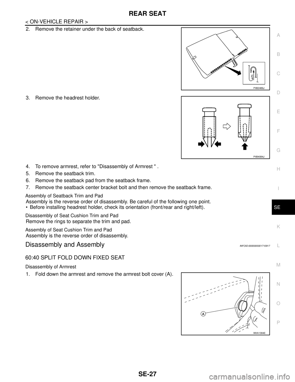
2. Remove the retainer under the back of seatback.
3. Remove the headrest holder.
4. To remove armrest, refer to "Disassembly of Armrest " .
5. Remove the seatback trim.
6. Remove the seatback pad from the seatback frame.
7. Remove the seatback center bracket bolt and then remove the seatback frame.
Assembly of Seatback Trim and Pad
Assembly is the reverse order of disassembly. Be careful of the following one point.
Before installing headrest holder, check its orientation (front/rear and right/left).
Disassembly of Seat Cushion Trim and Pad
Remove the rings to separate the trim and pad.
Assembly of Seat Cushion Trim and Pad
Assembly is the reverse order of disassembly.
Disassembly and AssemblyINFOID:0000000001710917
60:40 SPLIT FOLD DOWN FIXED SEAT
Disassembly of Armrest
1. Fold down the armrest and remove the armrest bolt cover (A).
PIIB2486J
PIIB4084J
WIIA1384E
Page 4625 of 5883

REAR SEAT
SE-29
< ON-VEHICLE REPAIR >
C
D
E
F
G
H
I
K
L
MA
B
SE
N
O
P
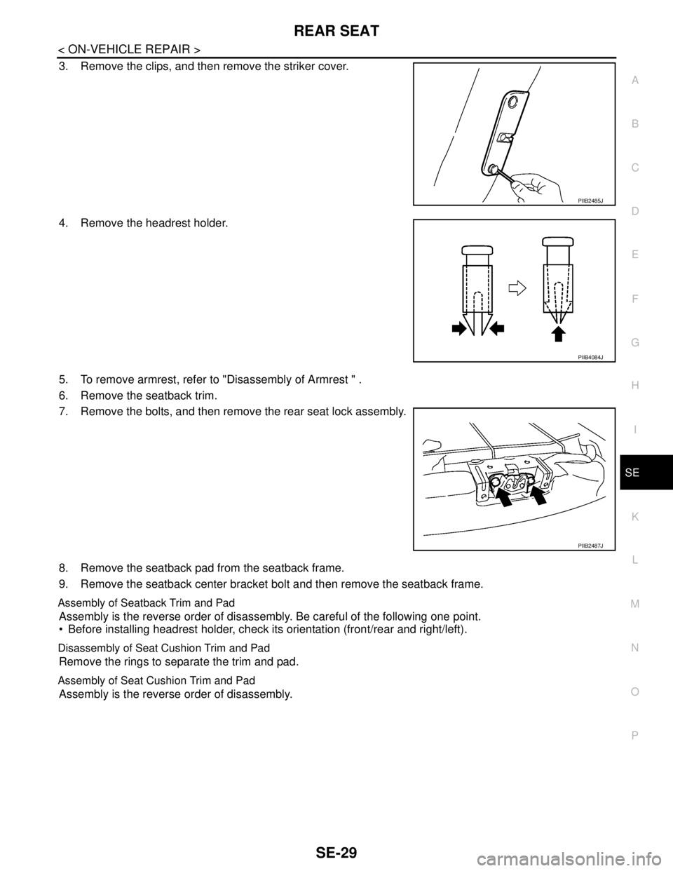
3. Remove the clips, and then remove the striker cover.
4. Remove the headrest holder.
5. To remove armrest, refer to "Disassembly of Armrest " .
6. Remove the seatback trim.
7. Remove the bolts, and then remove the rear seat lock assembly.
8. Remove the seatback pad from the seatback frame.
9. Remove the seatback center bracket bolt and then remove the seatback frame.
Assembly of Seatback Trim and Pad
Assembly is the reverse order of disassembly. Be careful of the following one point.
Before installing headrest holder, check its orientation (front/rear and right/left).
Disassembly of Seat Cushion Trim and Pad
Remove the rings to separate the trim and pad.
Assembly of Seat Cushion Trim and Pad
Assembly is the reverse order of disassembly.
PIIB2485J
PIIB4084J
PIIB2487J
Page 4635 of 5883
![NISSAN TIIDA 2007 Service Repair Manual SEC-10
< FUNCTION DIAGNOSIS >[WITH INTELLIGENT KEY SYSTEM]
INTELLIGENT KEY SYSTEM/ENGINE START FUNCTION
When any of the following condition are fulfilled key interlock solenoid will be unlocked. (Stee NISSAN TIIDA 2007 Service Repair Manual SEC-10
< FUNCTION DIAGNOSIS >[WITH INTELLIGENT KEY SYSTEM]
INTELLIGENT KEY SYSTEM/ENGINE START FUNCTION
When any of the following condition are fulfilled key interlock solenoid will be unlocked. (Stee](/manual-img/5/57395/w960_57395-4634.png)
SEC-10
< FUNCTION DIAGNOSIS >[WITH INTELLIGENT KEY SYSTEM]
INTELLIGENT KEY SYSTEM/ENGINE START FUNCTION
When any of the following condition are fulfilled key interlock solenoid will be unlocked. (Steering lock active)
When vehicle speed is below 4km/h (2mph) and the ignition switch is turned from ON to OFF.
When vehicle speed is over 4km/h (2mph) but less than 10km/h (6mph) in LOCK condition, and 3 second
passes after the ignition switch is turned from ON to OFF.
Component Parts LocationINFOID:0000000001404036
Component DescriptionINFOID:0000000001404037
1. BCM M18, M19, M20
(view with glove box removed)2. Intelligent Key Unit M52 3. Steering lock solenoid M6
(bottom view of steering column)
4. Security indicator lamp M31 5. ECM E16 6. Intelligent key warning buzzer (driver side) D6
(LHD: view with front door finisher removed)
7. Intelligent key warning buzzer (driver
side) D6
(RHD: view with front door finisher
removed)8. Intelligent Key warning buzzer
(trunk) B82 (sedan)
(view with trunk finisher LH re-
moved)
ALKIA0844ZZ
Component Reference
Intelligent Key unitSEC-34
BCMXX-XX, "*****"
Page 4641 of 5883
![NISSAN TIIDA 2007 Service Repair Manual SEC-16
< FUNCTION DIAGNOSIS >[WITH INTELLIGENT KEY SYSTEM]
DIAGNOSIS SYSTEM (BCM)
DATA MONITOR
ACTIVE TEST
THEFT ALM
THEFT ALM : CONSULT-III Function (BCM - THEFT ALM)INFOID:0000000001404048
APPLICATI NISSAN TIIDA 2007 Service Repair Manual SEC-16
< FUNCTION DIAGNOSIS >[WITH INTELLIGENT KEY SYSTEM]
DIAGNOSIS SYSTEM (BCM)
DATA MONITOR
ACTIVE TEST
THEFT ALM
THEFT ALM : CONSULT-III Function (BCM - THEFT ALM)INFOID:0000000001404048
APPLICATI](/manual-img/5/57395/w960_57395-4640.png)
SEC-16
< FUNCTION DIAGNOSIS >[WITH INTELLIGENT KEY SYSTEM]
DIAGNOSIS SYSTEM (BCM)
DATA MONITOR
ACTIVE TEST
THEFT ALM
THEFT ALM : CONSULT-III Function (BCM - THEFT ALM)INFOID:0000000001404048
APPLICATION ITEM
CONSULT-III performs the following functions via CAN communication with BCM.
DATA MONITOR
ACTIVE TEST
WORK SUPPORT
Diagnosis mode Function Description
DATA MONITOR The BCM input/output signals are displayed.
ACTIVE TEST The signals used to activate each device are forcibly supplied from Intelligent Key unit.
Monitor item Content
IGN ON SW Indicates [ON/OFF] condition of ignition switch in ON position.
KEY ON SW Indicates [ON/OFF] condition of key switch.
PUSH SW Indicates [ON/OFF] condition of ignition knob switch.
Test item Description
THEFT IND This test is able to check security indicator operation [ON/OFF].
Diagnosis mode Function Description
WORK SUPPORT Changes the setting for each system function.
DATA MONITOR The BCM input/output signals are displayed.
ACTIVE TEST The signals used to activate each device are forcibly supplied from BCM.
Monitor Item Condition
IGN ON SW Indicates [ON/OFF] condition of ignition switch in ON position.
ACC ON SW Indicates [ON/OFF] condition of ignition switch in ACC position.
PUSH SW Indicates [ON/OFF] condition of ignition knob switch.
KEY ON SW Indicates [ON/OFF] condition of key switch.
I-KEY LOCK Indicates [ON/OFF] condition of lock signal from Intelligent Key.
I-KEY UNLOCK Indicates [ON/OFF] condition of unlock signal from Intelligent Key.
DOOR SW-DR Indicates [ON/OFF] condition of front door switch (driver side).
DOOR SW-AS Indicates [ON/OFF] condition of front door switch (passenger side).
DOOR SW-RR Indicates [ON/OFF] condition of rear door switch RH.
DOOR SW-RL Indicates [ON/OFF] condition of rear door switch LH.
BACK DOOR SW Indicates [ON/OFF] condition of back door switch.
CDL LOCK SW Indicates [ON/OFF] condition of door lock and unlock switch.
CDL UNLOCK SW Indicates [ON/OFF] condition of door lock and unlock switch.
Test item Description
THEFT IND This test is able to check security indicator operation [ON/OFF].
FLASHER This test is able to check flasher operation [LH/RH/OFF].
Page 4644 of 5883
![NISSAN TIIDA 2007 Service Repair Manual DIAGNOSIS SYSTEM (INTELLIGENT KEY UNIT)
SEC-19
< FUNCTION DIAGNOSIS >[WITH INTELLIGENT KEY SYSTEM]
C
D
E
F
G
H
I
J
L
MA
B
SEC
N
O
P
ACTIVE TEST
Monitor Item Condition
PUSH SW Indicates [ON (pressed)/O NISSAN TIIDA 2007 Service Repair Manual DIAGNOSIS SYSTEM (INTELLIGENT KEY UNIT)
SEC-19
< FUNCTION DIAGNOSIS >[WITH INTELLIGENT KEY SYSTEM]
C
D
E
F
G
H
I
J
L
MA
B
SEC
N
O
P
ACTIVE TEST
Monitor Item Condition
PUSH SW Indicates [ON (pressed)/O](/manual-img/5/57395/w960_57395-4643.png)
DIAGNOSIS SYSTEM (INTELLIGENT KEY UNIT)
SEC-19
< FUNCTION DIAGNOSIS >[WITH INTELLIGENT KEY SYSTEM]
C
D
E
F
G
H
I
J
L
MA
B
SEC
N
O
P
ACTIVE TEST
Monitor Item Condition
PUSH SW Indicates [ON (pressed)/OFF (released)] condition of ignition knob switch.
KEY SW Indicates [ON (inserted)/OFF (removed)] condition of key switch.
DR REQ SW Indicates [ON (pressed)/OFF (released)] condition of door request switch (driver side).
AS REQ SWIndicates [ON (pressed)/OFF (released)] condition of door request switch (passenger
side).
BD/TR REQ SW Indicates [ON (pressed)/OFF (released)] condition of door request switch (back door).
IGN SWIndicates [ON (ON or START position)/OFF (other than ON and START position)] con-
dition of ignition switch ON position.
ACC SW Indicates [ON/OFF] condition of ignition switch ACC position.
STOP LAMP SW Indicates [ON/OFF] condition of stop lamp switch.
DOOR LOCK SIG Indicates [ON/OFF] condition of LOCK signal from Intelligent Key.
DOOR UNLOCK SIG Indicates [ON/OFF] condition of UNLOCK signal from Intelligent Key.
DOOR SW DRIndicates [OPEN/CLOSE] condition of front door switch (driver side) from BCM via CAN
communication.
DOOR SW ASIndicates [OPEN/CLOSE] condition of front door switch (passenger side) from BCM via
CAN communication.
DOOR SW RRIndicates [OPEN/CLOSE] condition of rear door switch (RH) from BCM via CAN com-
munication.
DOOR SW RLIndicates [OPEN/CLOSE] condition of rear door switch (LH) from BCM via CAN com-
munication.
DOOR BK SWIndicates [OPEN/CLOSE] condition of back door switch from BCM via CAN communi-
cation.
VEHICLE SPEEDDisplays the vehicle speed signal received from combination meter by numerical value
[km/h].
Test item Description
DOOR LOCK/UNLOCKThis test is able to check door lock/unlock operation.
ALL UNLK: All door lock actuators are unlocked.
DR UNLK: Door lock actuator (driver side) is unlocked.
AS UNLK: Door lock actuator (passenger side) is unlocked.
BK UNLK: This item is indicated, but inactive.
LOCK: All door lock actuator is locked.
ANTENNAThis test is able to check Intelligent Key antenna operation.
When the following condition are met, hazard warning lamps flash.
ROOM ANT1: Inside key antenna (console) detects Intelligent Key, when “ROOM
ANT1” is selected.
ROOM ANT2: Inside key antenna (instrument center/rear seat) detects Intelligent
Key, when “ROOM ANT2”is selected.
DRIVER ANT: Outside key antenna (driver side) detects Intelligent Key, when “DRIV-
ER ANT” is selected.
ASSIST ANT: Outside key antenna (passenger side) detects Intelligent Key, when
“ASSIST ANT” is selected.
BK DOOR ANT: Outside key antenna (rear bumper) detects Intelligent Key, when “BK
DOOR ANT” is selected.
OUTSIDE BUZZERThis test is able to check Intelligent Key warning buzzer operation.
ON
OFF
INSIDE BUZZERThis test is able to check warning chime in combination meter operation.
TAKE OUT: Take away warning chime sounds.
KNOB: Ignition knob switch warning chime sounds.
KEY: Key warning chime sounds.
OFF
Page 4694 of 5883
![NISSAN TIIDA 2007 Service Repair Manual BCM (BODY CONTROL MODULE)
SEC-69
< ECU DIAGNOSIS >[WITH INTELLIGENT KEY SYSTEM]
C
D
E
F
G
H
I
J
L
MA
B
SEC
N
O
P
REAR WIPER CONTROL
BCM detects a rear wiper stopping position according to a rear wiper NISSAN TIIDA 2007 Service Repair Manual BCM (BODY CONTROL MODULE)
SEC-69
< ECU DIAGNOSIS >[WITH INTELLIGENT KEY SYSTEM]
C
D
E
F
G
H
I
J
L
MA
B
SEC
N
O
P
REAR WIPER CONTROL
BCM detects a rear wiper stopping position according to a rear wiper](/manual-img/5/57395/w960_57395-4693.png)
BCM (BODY CONTROL MODULE)
SEC-69
< ECU DIAGNOSIS >[WITH INTELLIGENT KEY SYSTEM]
C
D
E
F
G
H
I
J
L
MA
B
SEC
N
O
P
REAR WIPER CONTROL
BCM detects a rear wiper stopping position according to a rear wiper auto stop signal.
When a rear wiper auto stop signal is in the condition listed below, BCM stops power supply to rear wiper after
rear wiper is activated for five seconds.
NOTE:
The above operation is repeated when operating the rear wiper switch one minute after the stop of the rear
wiper caused by Fail-safe.
TURN SIGNAL LAMP CONTROL
BCM detects the turn signal lamp circuit status from the terminal voltage.
BCM increases the turn signal lamp blinking speed if the bulb or harness open is detected with the turn signal
lamp operating.
NOTE:
The blinking speed is normal while activating the hazard warning lamp.
LIGHT & RAIN SENSOR MALFUNCTION DETECTION FUNCTION
BCM controls the following items when LIGHT & RAIN sensor has a malfunction.
Auto Light Control
Headlamp is turned ON.
Front Wiper Control
The condition just before the activation of Fail-safe is maintained until the front wiper switch is turned OFF.
DTC Inspection Priority ChartINFOID:0000000001404126
DTC IndexINFOID:0000000001404127
NOTE:
Details of time display
CRNT: Displays when there is a malfunction now or after returning to the normal condition until turning igni-
tion switch OFF → ON again.
Display contents of CONSULT Fail-safe Cancellation
B2190: NATS ANTENNA AMP Inhibits engine cranking
Inhibits steering lock unlocking (Intelligent Key unit)
Fuel cut (ECM)Erase DTC
B2191: DIFFERENCE OF KEY Inhibits engine cranking
Inhibits steering lock unlocking (Intelligent Key unit)
Fuel cut (ECM)Erase DTC
B2192: ID DISCORD BCM-ECM Fuel cut (ECM) Erase DTC
B2193: CHAIN OF BCM-ECM Fuel cut (ECM) Erase DTC
B2194: DISCORD BCM-I-KEY Inhibits engine cranking
Inhibits steering lock unlocking (Intelligent Key unit)
Fuel cut (ECM)Erase DTC
Ignition switch Rear wiper switch Auto stop signal
ONOFFRear wiper stop position signal cannot be
input 5 seconds.
ON The signal does not change for 5 seconds.
Priority DTC
1 U1000: CAN COMM CIRCUIT
U1010: CONTROL UNIT (CAN)
2 B2190: NATS ANTENNA AMP
B2191: DIFFERNCE OF KEY
B2192: ID DISCORD BCM-ECM
B2193: CHAIN OF BCM-ECM
B2194: DISCORD BCM-I-KEY