Page 4755 of 5883
SR-12
< ON-VEHICLE REPAIR >
SIDE AIR BAG (SATELLITE) SENSOR
SIDE AIR BAG (SATELLITE) SENSOR
Removal and InstallationINFOID:0000000001350510
REMOVAL
WARNING:
Do not reuse center pillar upper garnish if removed.
CAUTION:
Before servicing the SRS, turn ignition switch OFF, disconnect both battery cables and wait at least
3 minutes.
Do not disassemble the side air bag (satellite) sensor.
Do not use old nuts after removal; replace with new nuts.
Replace the side air bag (satellite) sensor if it has been
dropped or sustained an impact.
Check side air bag (satellite) sensor to make sure it is free of
deformities, dents, cracks or rust. If it shows any visible signs
of damage, replace it with a new one.
1. Disconnect both the negative and positive battery cables, then wait at least 3 minutes.
2. Remove the front seat belt retractor. Refer to SB-6, "
Removal and Installation of Front Seat Belt".
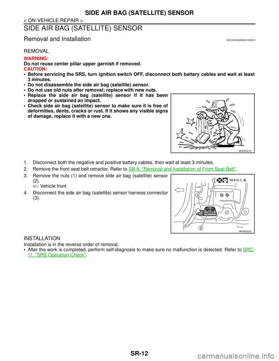
3. Remove the nuts (1) and remove side air bag (satellite) sensor
(2).
⇐: Vehicle front
4. Disconnect the side air bag (satellite) sensor harness connector
(3).
INSTALLATION
Installation is in the reverse order of removal.
After the work is completed, perform self-diagnosis to make sure no malfunction is detected. Refer to SRC-
11 , "SRS Operation Check".
WHIA0321E
WHIA0322E
Page 4757 of 5883
SR-14
< ON-VEHICLE REPAIR >
FRONT SEAT BELT PRE-TENSIONER
FRONT SEAT BELT PRE-TENSIONER
Removal and InstallationINFOID:0000000001350511
For removal and installation procedures, refer to SB-6, "Removal and Installation of Front Seat Belt".
Page 4758 of 5883
DIAGNOSIS SENSOR UNIT
SR-15
< ON-VEHICLE REPAIR >
C
D
E
F
G
I
J
K
L
MA
B
SR
N
O
P
DIAGNOSIS SENSOR UNIT
Removal and InstallationINFOID:0000000001350512
REMOVAL
WARNING:
Before disconnecting diagnosis sensor unit harness connector(s), be sure to disconnect harness con-
nectors from air bag modules and front seat belt pre-tensioner to prevent deployment by static elec-
tricity.
CAUTION:
Before servicing the SRS, turn the ignition switch OFF, disconnect both battery cables and wait at
least 3 minutes.
Do not disassemble diagnosis sensor unit.
Do not use old bolts; replace with new bolts.
Replace the diagnosis sensor unit if it has been dropped or sustained an impact.
Check diagnosis sensor unit bracket to make sure it is free of deformities, dents, cracks or rust. If it
shows any visible signs of damage, replace with new one.
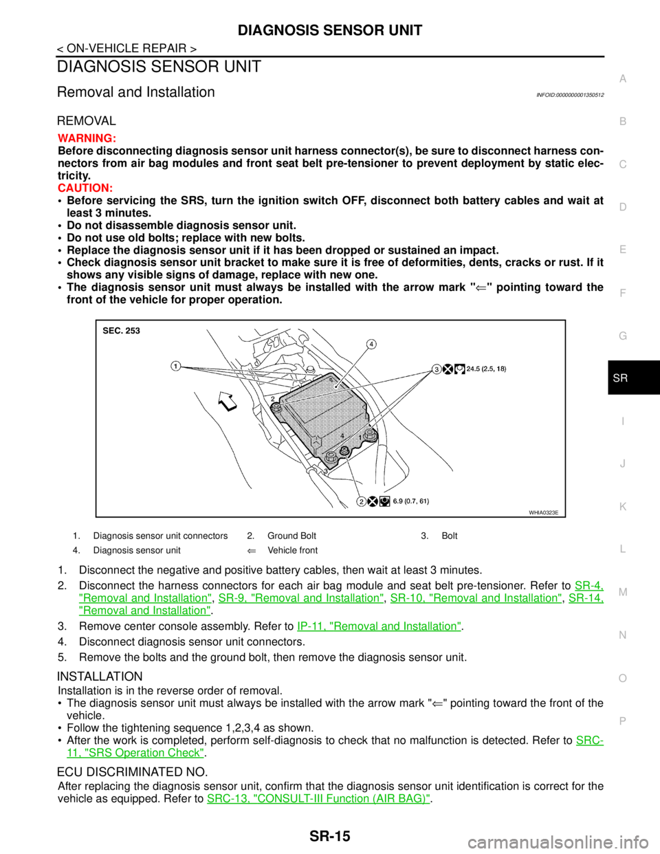
The diagnosis sensor unit must always be installed with the arrow mark "⇐" pointing toward the
front of the vehicle for proper operation.
1. Disconnect the negative and positive battery cables, then wait at least 3 minutes.
2. Disconnect the harness connectors for each air bag module and seat belt pre-tensioner. Refer to SR-4,
"Removal and Installation", SR-9, "Removal and Installation", SR-10, "Removal and Installation", SR-14,
"Removal and Installation".
3. Remove center console assembly. Refer to IP-11, "
Removal and Installation".
4. Disconnect diagnosis sensor unit connectors.
5. Remove the bolts and the ground bolt, then remove the diagnosis sensor unit.
INSTALLATION
Installation is in the reverse order of removal.
The diagnosis sensor unit must always be installed with the arrow mark "⇐" pointing toward the front of the
vehicle.
Follow the tightening sequence 1,2,3,4 as shown.
After the work is completed, perform self-diagnosis to check that no malfunction is detected. Refer to SRC-
11 , "SRS Operation Check".
ECU DISCRIMINATED NO.
After replacing the diagnosis sensor unit, confirm that the diagnosis sensor unit identification is correct for the
vehicle as equipped. Refer to SRC-13, "
CONSULT-III Function (AIR BAG)".
1. Diagnosis sensor unit connectors 2. Ground Bolt 3. Bolt
4. Diagnosis sensor unit⇐Vehicle front
WHIA0323E
Page 4760 of 5883
DISPOSAL OF AIR BAG MODULE AND SEAT BELT PRE-TENSIONER
SR-17
< ON-VEHICLE REPAIR >
C
D
E
F
G
I
J
K
L
MA
B
SR
N
O
P
*: If this lamp glows red, the tool is connected to the battery incorrectly.Reverse the connections and check the lamp glows green.
DEPLOYMENT OF AIR BAG MODULE (OUTSIDE OF VEHICLE)
Deployment of Driver Air Bag Module (Outside of Vehicle)
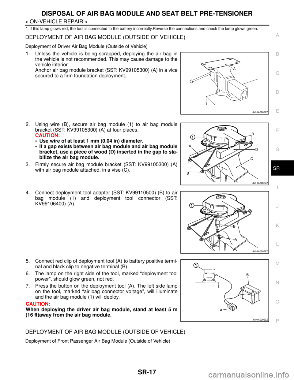
1. Unless the vehicle is being scrapped, deploying the air bag in
the vehicle is not recommended. This may cause damage to the
vehicle interior.
Anchor air bag module bracket (SST: KV99105300) (A) in a vice
secured to a firm foundation deployment.
2. Using wire (B), secure air bag module (1) to air bag module
bracket (SST: KV99105300) (A) at four places.
CAUTION:
Use wire of at least 1 mm (0.04 in) diameter.
If a gap exists between air bag module and air bag module
bracket, use a piece of wood (D) inserted in the gap to sta-
bilize the air bag module.
3. Firmly secure air bag module bracket (SST: KV99105300) (A)
with air bag module attached, in a vise (C).
4. Connect deployment tool adapter (SST: KV99110500) (B) to air
bag module (1) and deployment tool connector (SST:
KV99106400) (A).
5. Connect red clip of deployment tool (A) to battery positive termi-
nal and black clip to negative terminal (B).
6. The lamp on the right side of the tool, marked “deployment tool
power”, should glow green, not red.
7. Press the button on the deployment tool (A). The left side lamp
on the tool, marked “air bag connector voltage”, will illuminate
and the air bag module (1) will deploy.
CAUTION:
When deploying the driver air bag module, stand at least 5 m
(16 ft)away from the air bag module.
DEPLOYMENT OF AIR BAG MODULE (OUTSIDE OF VEHICLE)
Deployment of Front Passenger Air Bag Module (Outside of Vehicle)
JMHIA0208ZZ
JMHIA0206ZZ
JMHIA0207ZZ
JMHIA0209ZZ
Page 4761 of 5883
SR-18
< ON-VEHICLE REPAIR >
DISPOSAL OF AIR BAG MODULE AND SEAT BELT PRE-TENSIONER
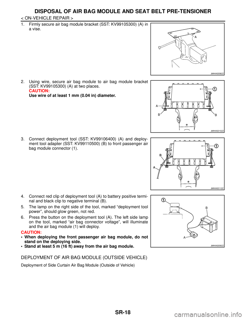
1. Firmly secure air bag module bracket (SST: KV99105300) (A) in
a vise.
2. Using wire, secure air bag module to air bag module bracket
(SST: KV99105300) (A) at two places.
CAUTION:
Use wire of at least 1 mm (0.04 in) diameter.
3. Connect deployment tool (SST: KV99106400) (A) and deploy-
ment tool adapter (SST: KV99110500) (B) to front passenger air
bag module connector (1).
4. Connect red clip of deployment tool (A) to battery positive termi-
nal and black clip to negative terminal (B).
5. The lamp on the right side of the tool, marked “deployment tool
power”, should glow green, not red.
6. Press the button on the deployment tool (A). The left side lamp
on the tool, marked “air bag connector voltage”, will illuminate
and the air bag module (1) will deploy.
CAUTION:
When deploying the front passenger air bag module, do not
stand on the deploying side.
Stand at least 5 m (16 ft) away from the air bag module.
DEPLOYMENT OF AIR BAG MODULE (OUTSIDE VEHICLE)
Deployment of Side Curtain Air Bag Module (Outside of Vehicle)
JMHIA0208ZZ
JMHIA0210ZZ
JMHIA0211ZZ
JMHIA0209ZZ
Page 4762 of 5883
DISPOSAL OF AIR BAG MODULE AND SEAT BELT PRE-TENSIONER
SR-19
< ON-VEHICLE REPAIR >
C
D
E
F
G
I
J
K
L
MA
B
SR
N
O
P
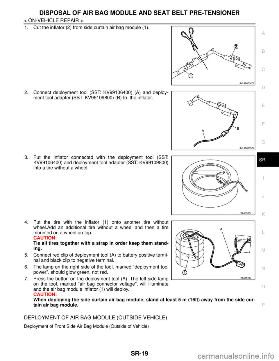
1. Cut the inflator (2) from side curtain air bag module (1).
2. Connect deployment tool (SST: KV99106400) (A) and deploy-
ment tool adapter (SST: KV99109800) (B) to the inflator.
3. Put the inflator connected with the deployment tool (SST:
KV99106400) and deployment tool adapter (SST: KV99109800)
into a tire without a wheel.
4. Put the tire with the inflator (1) onto another tire without
wheel.Add an additional tire without a wheel and then a tire
mounted on a wheel on top.
CAUTION:
Tie all tires together with a strap in order keep them stand-
ing.
5. Connect red clip of deployment tool (A) to battery positive termi-
nal and black clip to negative terminal.
6. The lamp on the right side of the tool, marked “deployment tool
power”, should glow green, not red.
7. Press the button on the deployment tool (A). The left side lamp
on the tool, marked “air bag connector voltage”, will illuminate
and the air bag module inflator (1) will deploy.
CAUTION:
When deploying the side curtain air bag module, stand at least 5 m (16ft) away from the side cur-
tain air bag module.
DEPLOYMENT OF AIR BAG MODULE (OUTSIDE VEHICLE)
Deployment of Front Side Air Bag Module (Outside of Vehicle)
JMHIA0064ZZ
JMHIA0065ZZ
PHIA0937J
PHIA1173E
Page 4763 of 5883
SR-20
< ON-VEHICLE REPAIR >
DISPOSAL OF AIR BAG MODULE AND SEAT BELT PRE-TENSIONER
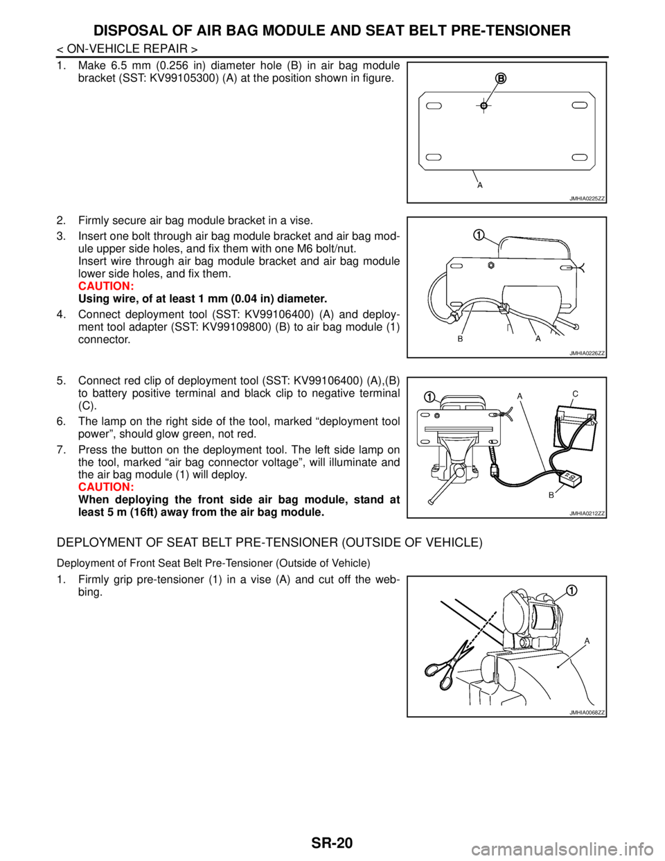
1. Make 6.5 mm (0.256 in) diameter hole (B) in air bag module
bracket (SST: KV99105300) (A) at the position shown in figure.
2. Firmly secure air bag module bracket in a vise.
3. Insert one bolt through air bag module bracket and air bag mod-
ule upper side holes, and fix them with one M6 bolt/nut.
Insert wire through air bag module bracket and air bag module
lower side holes, and fix them.
CAUTION:
Using wire, of at least 1 mm (0.04 in) diameter.
4. Connect deployment tool (SST: KV99106400) (A) and deploy-
ment tool adapter (SST: KV99109800) (B) to air bag module (1)
connector.
5. Connect red clip of deployment tool (SST: KV99106400) (A),(B)
to battery positive terminal and black clip to negative terminal
(C).
6. The lamp on the right side of the tool, marked “deployment tool
power”, should glow green, not red.
7. Press the button on the deployment tool. The left side lamp on
the tool, marked “air bag connector voltage”, will illuminate and
the air bag module (1) will deploy.
CAUTION:
When deploying the front side air bag module, stand at
least 5 m (16ft) away from the air bag module.
DEPLOYMENT OF SEAT BELT PRE-TENSIONER (OUTSIDE OF VEHICLE)
Deployment of Front Seat Belt Pre-Tensioner (Outside of Vehicle)
1. Firmly grip pre-tensioner (1) in a vise (A) and cut off the web-
bing.
JMHIA0225ZZ
JMHIA0226ZZ
JMHIA0212ZZ
JMHIA0068ZZ
Page 4764 of 5883
DISPOSAL OF AIR BAG MODULE AND SEAT BELT PRE-TENSIONER
SR-21
< ON-VEHICLE REPAIR >
C
D
E
F
G
I
J
K
L
MA
B
SR
N
O
P
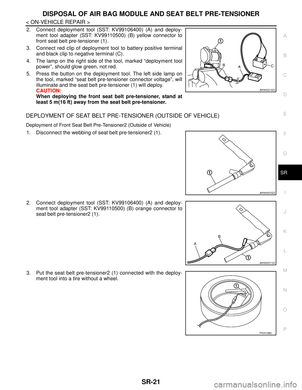
2. Connect deployment tool (SST: KV99106400) (A) and deploy-
ment tool adapter (SST: KV99110500) (B) yellow connector to
front seat belt pre-tensioner (1).
3. Connect red clip of deployment tool to battery positive terminal
and black clip to negative terminal (C).
4. The lamp on the right side of the tool, marked “deployment tool
power”, should glow green, not red.
5. Press the button on the deployment tool. The left side lamp on
the tool, marked “seat belt pre-tensioner connector voltage”, will
illuminate and the seat belt pre-tensioner (1) will deploy.
CAUTION:
When deploying the front seat belt pre-tensioner, stand at
least 5 m(16 ft) away from the seat belt pre-tensioner.
DEPLOYMENT OF SEAT BELT PRE-TENSIONER (OUTSIDE OF VEHICLE)
Deployment of Front Seat Belt Pre-Tensioner2 (Outside of Vehicle)
1. Disconnect the webbing of seat belt pre-tensioner2 (1).
2. Connect deployment tool (SST: KV99106400) (A) and deploy-
ment tool adapter (SST: KV99110500) (B) orange connector to
seat belt pre-tensioner2 (1).
3. Put the seat belt pre-tensioner2 (1) connected with the deploy-
ment tool into a tire without a wheel.
JMHIA0214ZZ
JMHIA0070ZZ
JMHIA0071ZZ
PHIA1288J