2007 NISSAN TIIDA front
[x] Cancel search: frontPage 4823 of 5883

SRC-54
< COMPONENT DIAGNOSIS >
B1209 – B1210 COLLISION DETECTION
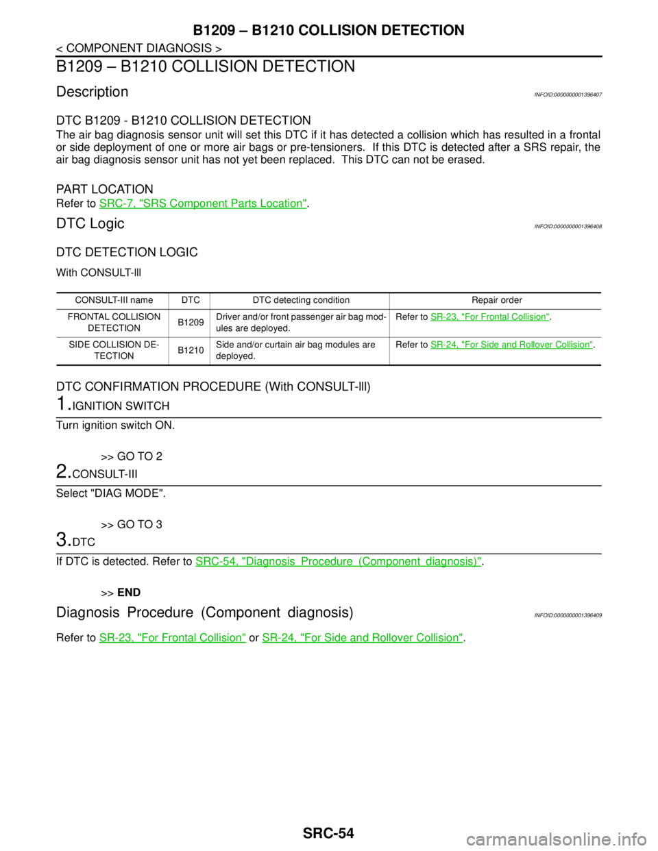
B1209 – B1210 COLLISION DETECTION
DescriptionINFOID:0000000001396407
DTC B1209 - B1210 COLLISION DETECTION
The air bag diagnosis sensor unit will set this DTC if it has detected a collision which has resulted in a frontal
or side deployment of one or more air bags or pre-tensioners. If this DTC is detected after a SRS repair, the
air bag diagnosis sensor unit has not yet been replaced. This DTC can not be erased.
PA R T L O C AT I O N
Refer to SRC-7, "SRS Component Parts Location".
DTC LogicINFOID:0000000001396408
DTC DETECTION LOGIC
With CONSULT-lll
DTC CONFIRMATION PROCEDURE (With CONSULT-lll)
1.IGNITION SWITCH
Turn ignition switch ON.
>> GO TO 2
2.CONSULT-III
Select "DIAG MODE".
>> GO TO 3
3.DTC
If DTC is detected. Refer to SRC-54, "
DiagnosisProcedure(Componentdiagnosis)".
>>END
Diagnosis Procedure (Component diagnosis)INFOID:0000000001396409
Refer to SR-23, "For Frontal Collision" or SR-24, "For Side and Rollover Collision".
CONSULT-III name DTC DTC detecting condition Repair order
FRONTAL COLLISION
DETECTIONB1209Driver and/or front passenger air bag mod-
ules are deployed.Refer to SR-23, "
For Frontal Collision".
SIDE COLLISION DE-
TECTIONB1210Side and/or curtain air bag modules are
deployed.Refer to SR-24, "
For Side and Rollover Collision".
Page 4846 of 5883
![NISSAN TIIDA 2007 Service Repair Manual DIAGNOSIS SENSOR UNIT
SRC-77
< ECU DIAGNOSIS >
C
D
E
F
G
I
J
K
L
MA
B
SRC
N
O
P
CONSULT-III name DTC DTC detecting condition Repair order
DRIVER AIRBAG MODULE
[OPEN]B1049Driver air bag module circuit NISSAN TIIDA 2007 Service Repair Manual DIAGNOSIS SENSOR UNIT
SRC-77
< ECU DIAGNOSIS >
C
D
E
F
G
I
J
K
L
MA
B
SRC
N
O
P
CONSULT-III name DTC DTC detecting condition Repair order
DRIVER AIRBAG MODULE
[OPEN]B1049Driver air bag module circuit](/manual-img/5/57395/w960_57395-4845.png)
DIAGNOSIS SENSOR UNIT
SRC-77
< ECU DIAGNOSIS >
C
D
E
F
G
I
J
K
L
MA
B
SRC
N
O
P
CONSULT-III name DTC DTC detecting condition Repair order
DRIVER AIRBAG MODULE
[OPEN]B1049Driver air bag module circuit (DR1) is
open
(including the spiral cable).1. Visually check the wiring harness connection.
2. Replace the harness if it has visible damage.
3. Replace the driver air bag module.
4. Replace the spiral cable.
5. Replace the air bag diagnosis sensor unit.
6. Replace the related harness. DRIVER AIRBAG MODULE
[VB-SHORT]B1050Driver air bag module circuit (DR1) is
shorted to a power supply circuit
(including the spiral cable).
DRIVER AIRBAG MODULE
[GND-SHORT]B1051Driver air bag module circuit (DR1) is
shorted to ground
(including the spiral cable).
DRIVER AIRBAG MODULE
[SHORT]B1052Driver air bag module circuits (DR1) are
shorted to each other
(including the spiral cable).
ASSIST A/B MODULE
[OPEN]B1065Front passenger air bag module circuit
(AS1) is open.1. Visually check the wiring harness connection.
2. Replace the harness if it has visible damage.
3. Replace the front passenger air bag module.
4. Replace the air bag diagnosis sensor unit.
5. Replace the related harness. ASSIST A/B MODULE
[VB-SHORT]B1066Front passenger air bag module circuit
(AS1) is shorted to a power supply cir-
cuit.
ASSIST A/B MODULE
[GND-SHORT]B1067Front passenger air bag module circuit
(AS1) is shorted to ground.
ASSIST A/B MODULE
[SHORT]B1068Front passenger air bag module circuits
(AS1) are shorted to each other.
SIDE MODULE LH
[OPEN]B1134Front LH side air bag module circuit is
open.1. Visually check the wiring harness connection.
2. Replace the harness if it has visible damage.
3. Replace the front LH seat back assembly.
4. Replace the air bag diagnosis sensor unit.
5. Replace the related harness. SIDE MODULE LH
[VB-SHORT]B1135Front LH side air bag module circuit is
shorted to a power supply circuit.
SIDE MODULE LH
[GND-SHORT]B1136Front LH side air bag module circuit is
shorted to ground.
SIDE MODULE LH
[SHORT]B1137Front LH side air bag module circuits are
shorted to each other.
SIDE MODULE RH
[OPEN]B1129Front RH side air bag module circuit is
open.1. Visually check the wiring harness connection.
2. Replace the harness if it has visible damage.
3. Replace the front RH seat back assembly.
4. Replace the air bag diagnosis sensor unit.
5. Replace the related harness. SIDE MODULE RH
[VB-SHORT]B1130Front RH side air bag module circuit is
shorted to a power supply circuit.
SIDE MODULE RH
[GND-SHORT]B1131Front RH side air bag module circuit is
shorted to ground.
SIDE MODULE RH
[SHORT]B1132
Front RH side air bag module circuits
are shorted to each other.
CURTAIN MODULE LH
[OPEN]B1150LH side curtain air bag module circuit is
open.1. Visually check the wiring harness connection.
2. Replace the harness if it has visible damage.
3. Replace the LH side curtain air bag module.
4. Replace the air bag diagnosis sensor unit.
5. Replace the related harness. CURTAIN MODULE LH
[VB-SHORT]B1151LH side curtain air bag module circuit is
shorted to a power supply circuit.
CURTAIN MODULE LH
[GND-SHORT]B1152LH side curtain air bag module circuit is
shorted to ground.
CURTAIN MODULE LH
[SHORT]B1153LH side curtain air bag module circuits
are shorted to each other.
CURTAIN MODULE RH
[OPEN]B1145RH side curtain air bag module circuit is
open.1. Visually check the wiring harness connection.
2. Replace the harness if it has visible damage.
3. Replace the RH side curtain air bag module.
4. Replace the air bag diagnosis sensor unit.
5. Replace the related harness. CURTAIN MODULE RH
[VB-SHORT]B1146RH side curtain air bag module circuit is
shorted to a power supply circuit.
CURTAIN MODULE RH
[GND-SHORT]B1147RH side curtain air bag module circuit is
shorted to ground.
CURTAIN MODULE RH
[SHORT]B1148RH side curtain air bag module circuits
are shorted to each other.
Page 4847 of 5883

SRC-78
< ECU DIAGNOSIS >
DIAGNOSIS SENSOR UNIT
Trouble Diagnosis without CONSULT-III
INFOID:0000000001396412
WARNING LAMP FLASH CODE CHART
NOTE:
Follow the procedures in numerical order when repairing malfunctioning parts. Confirm whether malfunction is
eliminated using air bag warning lamp each time repair is finished. If malfunction is still observed, proceed to
the next step. When malfunction is eliminated, further repair work is not required.
PRE-TEN FRONT LH
[OPEN]B1086LH seat belt pre-tensioner circuit is
open.1. Visually check the wiring harness connection.
2. Replace the harness if it has visible damage.
3. Replace the front LH seat belt pre-tensioner.
4. Replace the air bag diagnosis sensor unit.
5. Replace the related harness. PRE-TEN FRONT LH
[VB-SHORT]B1087LH seat belt pre-tensioner circuit is
shorted to a power supply circuit.
PRE-TEN FRONT LH
[GND-SHORT]B1088LH seat belt pre-tensioner circuit is
shorted to ground.
PRE-TEN FRONT LH
[SHORT]B1089LH seat belt pre-tensioner circuits are
shorted to each other.
PRE-TEN FRONT RH
[OPEN]B1081RH seat belt pre-tensioner circuit is
open.1. Visually check the wiring harness connection.
2. Replace the harness if it has visible damage.
3. Replace the front RH seat belt pre-tensioner.
4. Replace the air bag diagnosis sensor unit.
5. Replace the related harness. PRE-TEN FRONT RH
[VB-SHORT]B1082RH seat belt pre-tensioner circuit is
shorted to a power supply circuit.
PRE-TEN FRONT RH
[GND-SHORT]B1083RH seat belt pre-tensioner circuit is
shorted to ground.
PRE-TEN FRONT RH
[SHORT]B1084RH seat belt pre-tensioner circuits are
shorted to each other.
PRE-TEN2 FRONT LH
[OPEN]B1182Lap seat belt pre-tensioner circuit is
open.1. Visually check the wiring harness connection.
2. Replace the harness if it has visible damage.
3. Replace the front lap seat belt pre-tensioner.
4. Replace the air bag diagnosis sensor unit.
5. Replace the related harness. PRE-TEN2 FRONT LH
[VB-SHORT]B1183Lap seat belt pre-tensioner circuit is
shorted to a power supply circuit.
PRE-TEN2 FRONT LH
[GND-SHORT]B1184Lap seat belt pre-tensioner circuit is
shorted to ground.
PRE-TEN2 FRONT LH
[SHORT]B1185Lap seat belt pre-tensioner circuits are
shorted to each other.
CRASH ZONE SEN
[UNIT FAIL]B1033 Crash zone sensor has malfunctioned. 1. Visually check the wiring harness connection.
2. Replace the harness if it has visible damage.
3. Replace the crash zone sensor.
4. Replace the air bag diagnosis sensor unit.
5. Replace the related harness. B1034
CRASH ZONE SEN
[COMM FAIL]B1035Crash zone sensor communication er-
ror.
SATELLITE SENS LH
[UNIT FAIL]B1118 LH side air bag satellite sensor has mal-
functioned.1. Visually check the wiring harness connection.
2. Replace the harness if it has visible damage.
3. Replace the LH side air bag satellite sensor.
4. Replace the air bag diagnosis sensor unit.
5. Replace the related harness. B 111 9
SATELLITE SENS LH
[COMM FAIL]B1120LH side air bag satellite sensor commu-
nication error.
SATELLITE SENS RH
[UNIT FAIL]B1113 RH side air bag satellite sensor has mal-
functioned.1. Visually check the wiring harness connection.
2. Replace the harness if it has visible damage.
3. Replace the RH side air bag satellite sensor.
4. Replace the air bag diagnosis sensor unit.
5. Replace the related harness. B 111 4
SATELLITE SENS RH
[COMM FAIL]B 111 5RH side air bag satellite sensor commu-
nication error.
CONTROL UNIT B1XXXAir bag diagnosis sensor unit is malfunc-
tioning.1. Visually check the wiring harness connection.
2. Replace the harness if it has visible damage.
3. Replace the air bag diagnosis sensor unit.
4. Replace the related harness.
FRONTAL COLLISION DE-
TECTIONB1209Driver and/or front passenger air bag
modules are deployed.Refer to SR-23, "
For Frontal Collision".
SIDE COLLISION DETEC-
TIONB1210Side and/or curtain air bag modules are
deployed.Refer to SR-24, "
For Side and Rollover Collision". CONSULT-III name DTC DTC detecting condition Repair order
Page 4851 of 5883

SRC-82
< SYMPTOM DIAGNOSIS >
SRS AIR BAG SYSTEM
SYMPTOM DIAGNOSIS
SRS AIR BAG SYSTEM
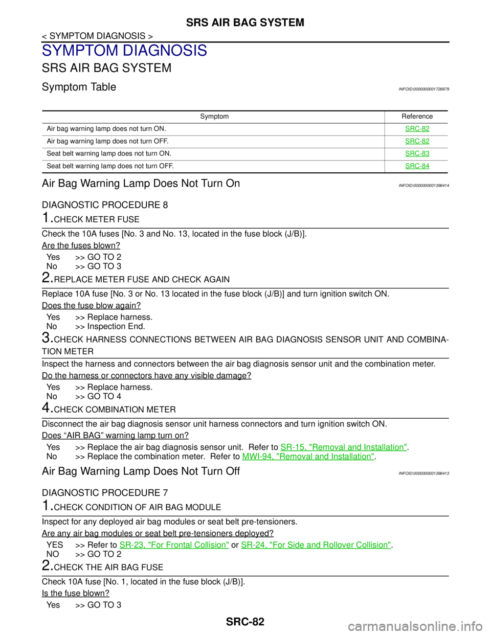
Symptom TableINFOID:0000000001726679
Air Bag Warning Lamp Does Not Turn OnINFOID:0000000001396414
DIAGNOSTIC PROCEDURE 8
1.CHECK METER FUSE
Check the 10A fuses [No. 3 and No. 13, located in the fuse block (J/B)].
Are the fuses blown?
Ye s > > G O T O 2
No >> GO TO 3
2.REPLACE METER FUSE AND CHECK AGAIN
Replace 10A fuse [No. 3 or No. 13 located in the fuse block (J/B)] and turn ignition switch ON.
Does the fuse blow again?
Yes >> Replace harness.
No >> Inspection End.
3.CHECK HARNESS CONNECTIONS BETWEEN AIR BAG DIAGNOSIS SENSOR UNIT AND COMBINA-
TION METER
Inspect the harness and connectors between the air bag diagnosis sensor unit and the combination meter.
Do the harness or connectors have any visible damage?
Yes >> Replace harness.
No >> GO TO 4
4.CHECK COMBINATION METER
Disconnect the air bag diagnosis sensor unit harness connectors and turn ignition switch ON.
Does
“AIR BAG” warning lamp turn on?
Yes >> Replace the air bag diagnosis sensor unit. Refer to SR-15, "Removal and Installation".
No >> Replace the combination meter. Refer to MWI-94, "
Removal and Installation".
Air Bag Warning Lamp Does Not Turn OffINFOID:0000000001396413
DIAGNOSTIC PROCEDURE 7
1.CHECK CONDITION OF AIR BAG MODULE
Inspect for any deployed air bag modules or seat belt pre-tensioners.
Are any air bag modules or seat belt pre-tensioners deployed?
YES >> Refer to SR-23, "For Frontal Collision" or SR-24, "For Side and Rollover Collision".
NO >> GO TO 2
2.CHECK THE AIR BAG FUSE
Check 10A fuse [No. 1, located in the fuse block (J/B)].
Is the fuse blown?
Ye s > > G O T O 3
Symptom Reference
Air bag warning lamp does not turn ON.SRC-82
Air bag warning lamp does not turn OFF.SRC-82
Seat belt warning lamp does not turn ON.SRC-83
Seat belt warning lamp does not turn OFF.SRC-84
Page 4855 of 5883

SRC-86
< PRECAUTION >
PRECAUTIONS
PRECAUTION
PRECAUTIONS
Precaution for Supplemental Restraint System (SRS) "AIR BAG" and "SEAT BELT
PRE-TENSIONER"
INFOID:0000000001396424
The Supplemental Restraint System such as “AIR BAG” and “SEAT BELT PRE-TENSIONER”, used along
with a front seat belt, helps to reduce the risk or severity of injury to the driver and front passenger for certain
types of collision. Information necessary to service the system safely is included in the SR and SB section of
this Service Manual.
WARNING:
To avoid rendering the SRS inoperative, which could increase the risk of personal injury or death in
the event of a collision which would result in air bag inflation, all maintenance must be performed by
an authorized NISSAN/INFINITI dealer.
Improper maintenance, including incorrect removal and installation of the SRS, can lead to personal
injury caused by unintentional activation of the system. For removal of Spiral Cable and Air Bag
Module, see the SR section.
Do not use electrical test equipment on any circuit related to the SRS unless instructed to in this
Service Manual. SRS wiring harnesses can be identified by yellow and/or orange harnesses or har-
ness connectors.
Precaution for SRS "AIR BAG" and "SEAT BELT PRE-TENSIONER" Service
INFOID:0000000001396425
Do not use electrical test equipment to check SRS circuits unless instructed to in this Service Manual.
Before servicing the SRS, turn ignition switch OFF, disconnect both battery cables and wait at least 3 min-
utes.
For approximately 3 minutes after the cables are removed, it is still possible for the air bag and seat belt pre-
tensioner to deploy. Therefore, do not work on any SRS connectors or wires until at least 3 minutes have
passed.
The air bag diagnosis sensor unit must always be installed with the arrow mark “⇐” pointing toward the front
of the vehicle for proper operation. Also check air bag diagnosis sensor unit for cracks, deformities or rust
before installation and replace as required.
The spiral cable must be aligned with the neutral position since its rotations are limited. Do not attempt to
turn steering wheel or column after removal of steering gear.
Handle air bag module carefully. Always place driver and front passenger air bag modules with the pad side
facing upward and seat mounted front side air bag module standing with the stud bolt side facing down.
Conduct self-diagnosis to check entire SRS for proper function after replacing any components.
After air bag inflates, the front instrument panel assembly should be replaced if damaged.
Page 4857 of 5883

ST-2
< PRECAUTION >
PRECAUTIONS
PRECAUTION
PRECAUTIONS
Precaution for Supplemental Restraint System (SRS) "AIR BAG" and "SEAT BELT
PRE-TENSIONER"
INFOID:0000000001282485
The Supplemental Restraint System such as “AIR BAG” and “SEAT BELT PRE-TENSIONER”, used along
with a front seat belt, helps to reduce the risk or severity of injury to the driver and front passenger for certain
types of collision. Information necessary to service the system safely is included in the SR and SB section of
this Service Manual.
WARNING:
• To avoid rendering the SRS inoperative, which could increase the risk of personal injury or death in
the event of a collision which would result in air bag inflation, all maintenance must be performed by
an authorized NISSAN/INFINITI dealer.
Improper maintenance, including incorrect removal and installation of the SRS, can lead to personal
injury caused by unintentional activation of the system. For removal of Spiral Cable and Air Bag
Module, see the SR section.
Do not use electrical test equipment on any circuit related to the SRS unless instructed to in this
Service Manual. SRS wiring harnesses can be identified by yellow and/or orange harnesses or har-
ness connectors.
Precaution Necessary for Steering Wheel Rotation After Battery Disconnect
INFOID:0000000001282486
NOTE:
This procedure is applied only to models with Intelligent Key system and NATS (NISSAN ANTI-THEFT SYS-
TEM).
Remove and install all control units after disconnecting both battery cables with the ignition switch in the
″LOCK″ position.
Always use CONSULT-III to perform self-diagnosis as a part of each function inspection after finishing work.
If DTC is detected, perform trouble diagnosis according to self-diagnostic results.
For models equipped with the Intelligent Key system and NATS, an electrically controlled steering lock mech-
anism is adopted on the key cylinder.
For this reason, if the battery is disconnected or if the battery is discharged, the steering wheel will lock and
steering wheel rotation will become impossible.
If steering wheel rotation is required when battery power is interrupted, follow the procedure below before
starting the repair operation.
OPERATION PROCEDURE
1. Connect both battery cables.
NOTE:
Supply power using jumper cables if battery is discharged.
2. Use the Intelligent Key or mechanical key to turn the ignition switch to the ″ACC″ position. At this time, the
steering lock will be released.
3. Disconnect both battery cables. The steering lock will remain released and the steering wheel can be
rotated.
4. Perform the necessary repair operation.
5. When the repair work is completed, return the ignition switch to the ″LOCK″ position before connecting
the battery cables. (At this time, the steering lock mechanism will engage.)
6. Perform a self-diagnosis check of all control units using CONSULT-III.
Precaution for Steering SystemINFOID:0000000001282487
Observe the following precautions when disassembling.
- Before disassembly, thoroughly clean the outside of the unit.
- Disassembly should be done in a clean work area. It is important to prevent the internal parts from becoming
contaminated by dirt or other foreign matter.
- For easier and proper assembly, place disassembled parts in order on a parts rack.
Page 4861 of 5883

ST-6
< ON-VEHICLE MAINTENANCE >
STEERING WHEEL
ON-VEHICLE MAINTENANCE
STEERING WHEEL
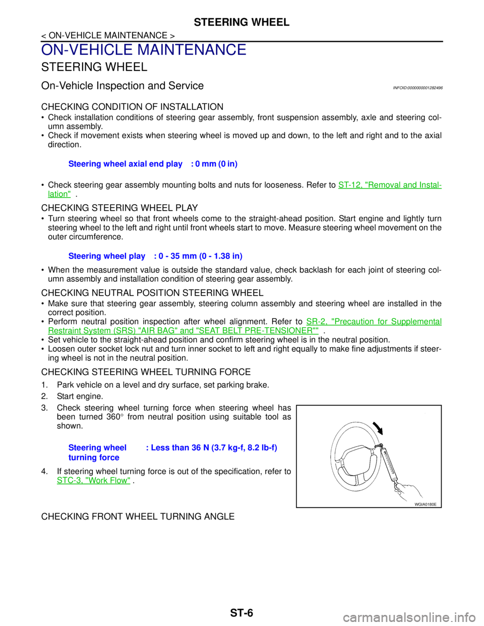
On-Vehicle Inspection and ServiceINFOID:0000000001282496
CHECKING CONDITION OF INSTALLATION
Check installation conditions of steering gear assembly, front suspension assembly, axle and steering col-
umn assembly.
Check if movement exists when steering wheel is moved up and down, to the left and right and to the axial
direction.
Check steering gear assembly mounting bolts and nuts for looseness. Refer to ST-12, "
Removal and Instal-
lation" .
CHECKING STEERING WHEEL PLAY
Turn steering wheel so that front wheels come to the straight-ahead position. Start engine and lightly turn
steering wheel to the left and right until front wheels start to move. Measure steering wheel movement on the
outer circumference.
When the measurement value is outside the standard value, check backlash for each joint of steering col-
umn assembly and installation condition of steering gear assembly.
CHECKING NEUTRAL POSITION STEERING WHEEL
Make sure that steering gear assembly, steering column assembly and steering wheel are installed in the
correct position.
Perform neutral position inspection after wheel alignment. Refer to SR-2, "
Precaution for Supplemental
Restraint System (SRS) "AIR BAG" and "SEAT BELT PRE-TENSIONER"" .
Set vehicle to the straight-ahead position and confirm steering wheel is in the neutral position.
Loosen outer socket lock nut and turn inner socket to left and right equally to make fine adjustments if steer-
ing wheel is not in the neutral position.
CHECKING STEERING WHEEL TURNING FORCE
1. Park vehicle on a level and dry surface, set parking brake.
2. Start engine.
3. Check steering wheel turning force when steering wheel has
been turned 360° from neutral position using suitable tool as
shown.
4. If steering wheel turning force is out of the specification, refer to
STC-3, "
Work Flow" .
CHECKING FRONT WHEEL TURNING ANGLE
Steering wheel axial end play : 0 mm (0 in)
Steering wheel play : 0 - 35 mm (0 - 1.38 in)
Steering wheel
turning force: Less than 36 N (3.7 kg-f, 8.2 lb-f)
WGIA0180E
Page 4862 of 5883

STEERING WHEEL
ST-7
< ON-VEHICLE MAINTENANCE >
C
D
E
F
H
I
J
K
L
MA
B
ST
N
O
P
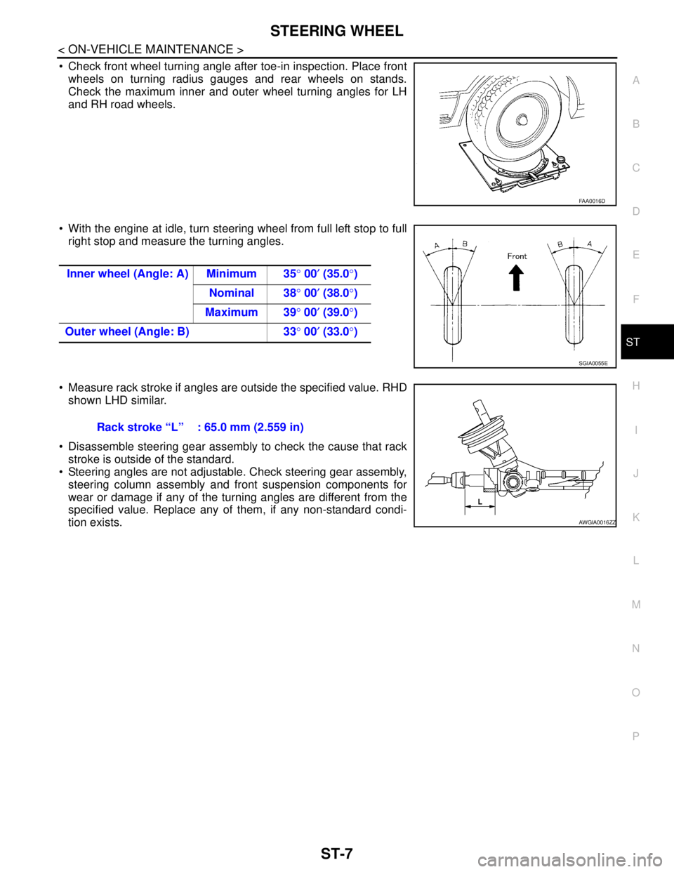
Check front wheel turning angle after toe-in inspection. Place front
wheels on turning radius gauges and rear wheels on stands.
Check the maximum inner and outer wheel turning angles for LH
and RH road wheels.
With the engine at idle, turn steering wheel from full left stop to full
right stop and measure the turning angles.
Measure rack stroke if angles are outside the specified value. RHD
shown LHD similar.
Disassemble steering gear assembly to check the cause that rack
stroke is outside of the standard.
Steering angles are not adjustable. Check steering gear assembly,
steering column assembly and front suspension components for
wear or damage if any of the turning angles are different from the
specified value. Replace any of them, if any non-standard condi-
tion exists.
FAA0016D
Inner wheel (Angle: A) Minimum 35° 00′ (35.0°)
Nominal 38° 00′ (38.0°)
Maximum 39° 00′ (39.0°)
Outer wheel (Angle: B) 33° 00′ (33.0°)
SGIA0055E
Rack stroke “L” : 65.0 mm (2.559 in)
AWGIA0016ZZ