2007 NISSAN TIIDA front
[x] Cancel search: frontPage 4863 of 5883

ST-8
< ON-VEHICLE REPAIR >
STEERING WHEEL
ON-VEHICLE REPAIR
STEERING WHEEL
Removal and InstallationINFOID:0000000001282499
REMOVAL
NOTE:
When reconnecting spiral cable, secure cable with a tape so that case and rotating part keep aligned. This will
omit neutral position alignment procedure during spiral cable installation.
1. Set front wheels to straight-ahead position.
2. Remove driver air bag module. Refer to SR-4, "
Removal and Installation" .
3. Remove steering wheel lock nut after steering is locked.
4. Remove steering wheel.
INSTALLATION
Installation is in the reverse order of removal.
CAUTION:
Do not run spiral cable idle needlessly. And do not turn it more than necessary (or it leads to discon-
nection of the cable).
NOTE:
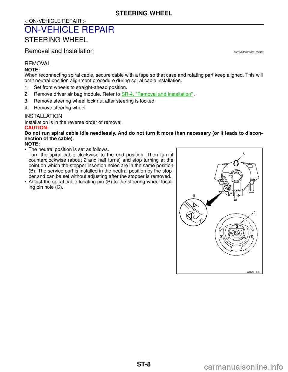
The neutral position is set as follows.
Turn the spiral cable clockwise to the end position. Then turn it
counterclockwise (about 2 and half turns) and stop turning at the
point on which the stopper insertion holes are in the same position
(B). The service part is installed in the neutral position by the stop-
per and can be set without adjusting after the stopper is removed.
Adjust the spiral cable locating pin (B) to the steering wheel locat-
ing pin hole (C).
WGIA0183E
Page 4864 of 5883

STEERING COLUMN
ST-9
< ON-VEHICLE REPAIR >
C
D
E
F
H
I
J
K
L
MA
B
ST
N
O
P
STEERING COLUMN
Removal and InstallationINFOID:0000000001282500
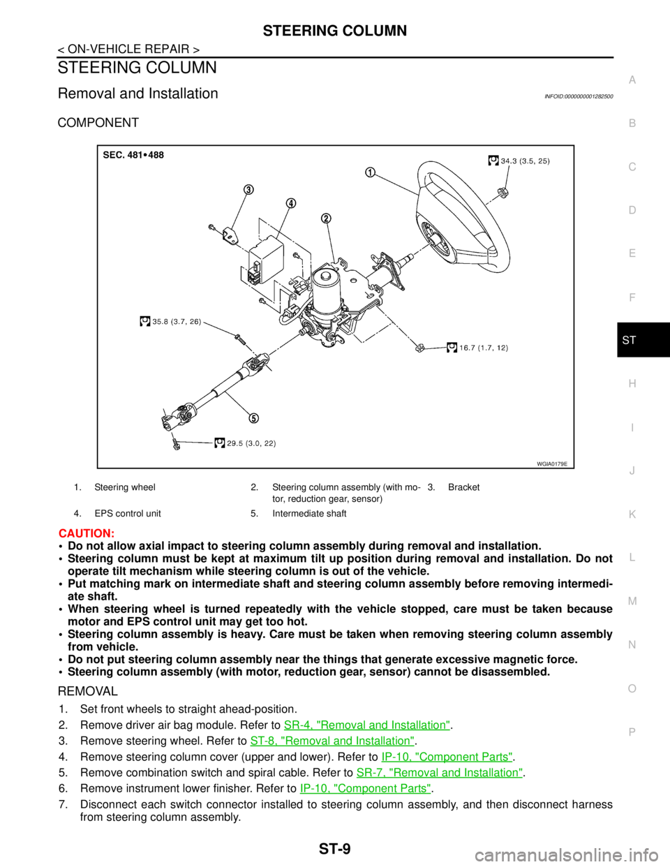
COMPONENT
CAUTION:
Do not allow axial impact to steering column assembly during removal and installation.
Steering column must be kept at maximum tilt up position during removal and installation. Do not
operate tilt mechanism while steering column is out of the vehicle.
Put matching mark on intermediate shaft and steering column assembly before removing intermedi-
ate shaft.
When steering wheel is turned repeatedly with the vehicle stopped, care must be taken because
motor and EPS control unit may get too hot.
Steering column assembly is heavy. Care must be taken when removing steering column assembly
from vehicle.
Do not put steering column assembly near the things that generate excessive magnetic force.
Steering column assembly (with motor, reduction gear, sensor) cannot be disassembled.
REMOVAL
1. Set front wheels to straight ahead-position.
2. Remove driver air bag module. Refer to SR-4, "
Removal and Installation".
3. Remove steering wheel. Refer to ST-8, "
Removal and Installation".
4. Remove steering column cover (upper and lower). Refer to IP-10, "
Component Parts".
5. Remove combination switch and spiral cable. Refer to SR-7, "
Removal and Installation".
6. Remove instrument lower finisher. Refer to IP-10, "
Component Parts".
7. Disconnect each switch connector installed to steering column assembly, and then disconnect harness
from steering column assembly.
1. Steering wheel 2. Steering column assembly (with mo-
tor, reduction gear, sensor)3. Bracket
4. EPS control unit 5. Intermediate shaft
WGIA0179E
Page 4867 of 5883

ST-12
< ON-VEHICLE REPAIR >
STEERING GEAR
STEERING GEAR
Removal and InstallationINFOID:0000000001282501
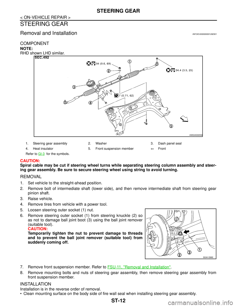
COMPONENT
NOTE:
RHD shown LHD similar.
CAUTION:
Spiral cable may be cut if steering wheel turns while separating steering column assembly and steer-
ing gear assembly. Be sure to secure steering wheel using string to avoid turning.
REMOVAL
1. Set vehicle to the straight-ahead position.
2. Remove bolt of intermediate shaft (lower side), and then remove intermediate shaft from steering gear
pinion shaft.
3. Raise vehicle.
4. Remove tires from vehicle with a power tool.
5. Loosen steering outer socket (1) nut.
6. Remove steering outer socket (1) from steering knuckle (2) so
as not to damage ball joint boot (3) using the ball joint remover
(suitable tool).
CAUTION:
Temporarily tighten the nut to prevent damage to threads
and to prevent the ball joint remover (suitable tool) from
suddenly coming off.
7. Remove front suspension member. Refer to FSU-11, "
Removal and Installation".
8. Remove mounting bolts and nuts of steering gear assembly, then remove steering gear assembly from
front suspension member.
INSTALLATION
Installation is in the reverse order of removal.
Clean mounting surface on the body side of fire wall seal when installing steering gear assembly.
1. Steering gear assembly 2. Washer 3. Dash panel seal
4. Heat insulator 5. Front suspension member⇐Front
Refer to GI-3
for the symbols.
AWGIA0020GB
SGIA1298E
Page 4869 of 5883

ST-14
< DISASSEMBLY AND ASSEMBLY >
STEERING GEAR
DISASSEMBLY AND ASSEMBLY
STEERING GEAR
Disassembly and AssemblyINFOID:0000000001282504
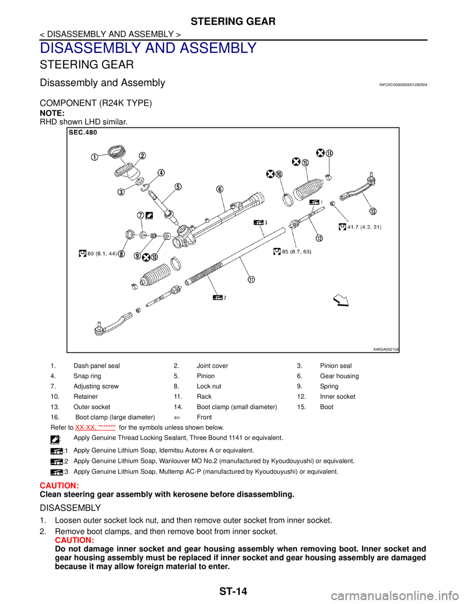
COMPONENT (R24K TYPE)
NOTE:
RHD shown LHD similar.
CAUTION:
Clean steering gear assembly with kerosene before disassembling.
DISASSEMBLY
1. Loosen outer socket lock nut, and then remove outer socket from inner socket.
2. Remove boot clamps, and then remove boot from inner socket.
CAUTION:
Do not damage inner socket and gear housing assembly when removing boot. Inner socket and
gear housing assembly must be replaced if inner socket and gear housing assembly are damaged
because it may allow foreign material to enter.
1. Dash panel seal 2. Joint cover 3. Pinion seal
4. Snap ring 5. Pinion 6. Gear housing
7. Adjusting screw 8. Lock nut 9. Spring
10. Retainer 11. Rack 12. Inner socket
13. Outer socket 14. Boot clamp (small diameter) 15. Boot
16. Boot clamp (large diameter)⇐Front
Refer to XX-XX, "*****"
for the symbols unless shown below.
:Apply Genuine Thread Locking Sealant, Three Bound 1141 or equivalent.
:1Apply Genuine Lithium Soap, Idemitsu Autorex A or equivalent.
:2Apply Genuine Lithium Soap, Wanlouver MO No.2 (manufactured by Kyoudouyushi) or equivalent.
:3Apply Genuine Lithium Soap, Multemp AC-P (manufactured by Kyoudouyushi) or equivalent.
AWGIA0021GB
Page 4896 of 5883
![NISSAN TIIDA 2007 Service Repair Manual STC-22
< ECU DIAGNOSIS >[EPS]
EPS CONTROL UNIT
ECU DIAGNOSIS
EPS CONTROL UNIT
EPS Control Unit Input/Output Signal Reference ValueINFOID:0000000001716757
SPECIFICATIONS WITH CONSULT-III
CAUTION:
The o NISSAN TIIDA 2007 Service Repair Manual STC-22
< ECU DIAGNOSIS >[EPS]
EPS CONTROL UNIT
ECU DIAGNOSIS
EPS CONTROL UNIT
EPS Control Unit Input/Output Signal Reference ValueINFOID:0000000001716757
SPECIFICATIONS WITH CONSULT-III
CAUTION:
The o](/manual-img/5/57395/w960_57395-4895.png)
STC-22
< ECU DIAGNOSIS >[EPS]
EPS CONTROL UNIT
ECU DIAGNOSIS
EPS CONTROL UNIT
EPS Control Unit Input/Output Signal Reference ValueINFOID:0000000001716757
SPECIFICATIONS WITH CONSULT-III
CAUTION:
The output signal indicates the EPS control unit calculation date. The normal values will be displayed
even in the event that the output circuit (harness) is open.
*1: In the front of the value, “L” is displayed at steering left and “R” is displayed at steering right.
*2: Almost in accordance with the value of “MOTOR SIG”. It is not a malfunction though these values are not accorded when steering
quickly.
*3: It is not a malfunction, though it might not be corresponding just after ignition switch is turned ON.
*4: It turns to OFF after waiting for a short period of time.Monitor item (Unit) Content Condition Display value
MOTOR VOL (V)Power supply voltage for
EPS control unitIgnition switch: ON Battery voltage
TORQUE SENSOR (Nm)Steering wheel turning
forceEngine runningSteering wheel: Not
steering (There is no
steering force) 0.00 Nm
Steering wheel: Steer-
ing0 – 8.19 Nm
*1 (The value
is changed according to
steering left or right)
MOTOR SIG (A)Command current to EPS
motorEngine runningSteering wheel: Not
steering (There is no
steering force)0.00 A
Steering wheel: Steer-
ing0 – 65.00 A (The value is
changed according to
steering left or right)
MOTOR CURRENT (A)Consumption current of
EPS motorEngine runningSteering wheel: Not
steering (There is no
steering force)0.00 A
Steering wheel: Steer-
ing0 – 65.00 A
*2 (The value
is changed according to
steering left or right)
VEHICLE SPEED (km/h) or (mph) Vehicle speedVehicle stopped 0 km/h (0 mph)
While drivingApproximately equal to
the indication on speed-
ometer (Inside of ±10%)
*3
WARNING LAMP (ON/OFF)EPS warning lamp condi-
tionEPS warning lamp: ON ON
EPS warning lamp: OFF OFF
DERATING STAT (ON/OFF) Protect overload status Engine runningSteering wheel: Nor-
mal steeringOFF
Steering wheel: Steer-
ing over the stopON
*4
ENGINE STATUS (RUN/STOP) Engine statusEngine stopped
(Engine speed: Less than 400 rpm)STOP
Engine running
(Engine speed: 400 rpm or more)RUN
Page 4910 of 5883
![NISSAN TIIDA 2007 Service Repair Manual STC-36
< PRECAUTION >[EPS]
PRECAUTIONS
PRECAUTION
PRECAUTIONS
Precaution for Supplemental Restraint System (SRS) "AIR BAG" and "SEAT BELT
PRE-TENSIONER"
INFOID:0000000001697712
The Supplemental Restr NISSAN TIIDA 2007 Service Repair Manual STC-36
< PRECAUTION >[EPS]
PRECAUTIONS
PRECAUTION
PRECAUTIONS
Precaution for Supplemental Restraint System (SRS) "AIR BAG" and "SEAT BELT
PRE-TENSIONER"
INFOID:0000000001697712
The Supplemental Restr](/manual-img/5/57395/w960_57395-4909.png)
STC-36
< PRECAUTION >[EPS]
PRECAUTIONS
PRECAUTION
PRECAUTIONS
Precaution for Supplemental Restraint System (SRS) "AIR BAG" and "SEAT BELT
PRE-TENSIONER"
INFOID:0000000001697712
The Supplemental Restraint System such as “AIR BAG” and “SEAT BELT PRE-TENSIONER”, used along
with a front seat belt, helps to reduce the risk or severity of injury to the driver and front passenger for certain
types of collision. Information necessary to service the system safely is included in the SR and SB section of
this Service Manual.
WARNING:
To avoid rendering the SRS inoperative, which could increase the risk of personal injury or death in
the event of a collision which would result in air bag inflation, all maintenance must be performed by
an authorized NISSAN/INFINITI dealer.
Improper maintenance, including incorrect removal and installation of the SRS, can lead to personal
injury caused by unintentional activation of the system. For removal of Spiral Cable and Air Bag
Module, see the SR section.
Do not use electrical test equipment on any circuit related to the SRS unless instructed to in this
Service Manual. SRS wiring harnesses can be identified by yellow and/or orange harnesses or har-
ness connectors.
Precaution Necessary for Steering Wheel Rotation After Battery Disconnect
INFOID:0000000001716731
NOTE:
This Procedure is applied only to models with Intelligent Key system and NATS (NISSAN ANTI-THEFT SYS-
TEM).
Remove and install all control units after disconnecting both battery cables with the ignition knob in the
″LOCK″ position.
Always use CONSULT-III to perform self-diagnosis as a part of each function inspection after finishing work.
If DTC is detected, perform trouble diagnosis according to self-diagnostic results.
For models equipped with the Intelligent Key system and NATS, an electrically controlled steering lock mech-
anism is adopted on the key cylinder.
For this reason, if the battery is disconnected or if the battery is discharged, the steering wheel will lock and
steering wheel rotation will become impossible.
If steering wheel rotation is required when battery power is interrupted, follow the procedure below before
starting the repair operation.
OPERATION PROCEDURE
1. Connect both battery cables.
NOTE:
Supply power using jumper cables if battery is discharged.
2. Use the Intelligent Key or mechanical key to turn the ignition switch to the ″ACC″ position. At this time, the
steering lock will be released.
3. Disconnect both battery cables. The steering lock will remain released and the steering wheel can be
rotated.
4. Perform the necessary repair operation.
5. When the repair work is completed, return the ignition switch to the ″LOCK″ position before connecting
the battery cables. (At this time, the steering lock mechanism will engage.)
6. Perform a self-diagnosis check of all control units using CONSULT-III.
Service Notice or Precaution for EPS SystemINFOID:0000000001697713
CAUTION:
Check or confirm the following item when performing the trouble diagnosis.
Check any possible causes by interviewing the symptom and it’s condition from the customer if any
malfunction, such as EPS warning lamp turns ON, occurs.
Check if air pressure and size of tires are proper, the specified part is used for the steering wheel,
and control unit is genuine part.
Page 4923 of 5883
![NISSAN TIIDA 2007 Service Repair Manual STR-12
< PRECAUTION >[HR16DE]
PRECAUTIONS
PRECAUTION
PRECAUTIONS
Precaution for Supplemental Restraint System (SRS) "AIR BAG" and "SEAT BELT
PRE-TENSIONER"
INFOID:0000000001689454
The Supplemental Re NISSAN TIIDA 2007 Service Repair Manual STR-12
< PRECAUTION >[HR16DE]
PRECAUTIONS
PRECAUTION
PRECAUTIONS
Precaution for Supplemental Restraint System (SRS) "AIR BAG" and "SEAT BELT
PRE-TENSIONER"
INFOID:0000000001689454
The Supplemental Re](/manual-img/5/57395/w960_57395-4922.png)
STR-12
< PRECAUTION >[HR16DE]
PRECAUTIONS
PRECAUTION
PRECAUTIONS
Precaution for Supplemental Restraint System (SRS) "AIR BAG" and "SEAT BELT
PRE-TENSIONER"
INFOID:0000000001689454
The Supplemental Restraint System such as “AIR BAG” and “SEAT BELT PRE-TENSIONER”, used along
with a front seat belt, helps to reduce the risk or severity of injury to the driver and front passenger for certain
types of collision. Information necessary to service the system safely is included in the SR and SB section of
this Service Manual.
WARNING:
• To avoid rendering the SRS inoperative, which could increase the risk of personal injury or death in
the event of a collision which would result in air bag inflation, all maintenance must be performed by
an authorized NISSAN/INFINITI dealer.
Improper maintenance, including incorrect removal and installation of the SRS, can lead to personal
injury caused by unintentional activation of the system. For removal of Spiral Cable and Air Bag
Module, see the SR section.
Do not use electrical test equipment on any circuit related to the SRS unless instructed to in this
Service Manual. SRS wiring harnesses can be identified by yellow and/or orange harnesses or har-
ness connectors.
Page 4924 of 5883
![NISSAN TIIDA 2007 Service Repair Manual STARTER MOTOR
STR-13
< ON-VEHICLE REPAIR >[HR16DE]
C
D
E
F
G
H
I
J
K
L
MA
STR
N
P O
ON-VEHICLE REPAIR
STARTER MOTOR
Removal and InstallationINFOID:0000000001689433
REMOVAL
1. Disconnect the battery ca NISSAN TIIDA 2007 Service Repair Manual STARTER MOTOR
STR-13
< ON-VEHICLE REPAIR >[HR16DE]
C
D
E
F
G
H
I
J
K
L
MA
STR
N
P O
ON-VEHICLE REPAIR
STARTER MOTOR
Removal and InstallationINFOID:0000000001689433
REMOVAL
1. Disconnect the battery ca](/manual-img/5/57395/w960_57395-4923.png)
STARTER MOTOR
STR-13
< ON-VEHICLE REPAIR >[HR16DE]
C
D
E
F
G
H
I
J
K
L
MA
STR
N
P O
ON-VEHICLE REPAIR
STARTER MOTOR
Removal and InstallationINFOID:0000000001689433
REMOVAL
1. Disconnect the battery cable from the negative terminal.
2. Remove “B” terminal nut and “B” terminal harness.
3. Remove “S” terminal nut and “S” terminal harness.
4. Remove starter motor bolts.
5. Remove starter motor upward from the vehicle.
INSTALLATION
Installation is in the reverse order of removal.
CAUTION:
Be sure to tighten “B” terminal nut carefully.
1. Cylinder block 2. “B” terminal harness 3. “S” terminal harness
4. Starter motor Vehicle front
PKIC0987E